International Research Journal of Engineering and Technology (IRJET) e ISSN: 2395 0056

Volume: 09 Issue: 07 | July 2022 www.irjet.net p ISSN: 2395 0072
International Research Journal of Engineering and Technology (IRJET) e ISSN: 2395 0056
Volume: 09 Issue: 07 | July 2022 www.irjet.net p ISSN: 2395 0072
1 PG Scholar, Department of PSE, K. S. Rangasamy College of Technology, Tiruchengode Namakkal, India
2 Assistant Professor, Department of EEE, K. S. Rangasamy College of Technology, Tiruchengode, Namakkal, India
3 PG Scholar, Department of PSE, K. S. Rangasamy College of Technology, Tiruchengode, Namakkal, India ***
Abstract - The performance of a grounding grid for photovoltaic (PV) systems protected by independent lightning rods is discussed in this article. Several grounding grid configurations are investigated, and the finite difference time domain (FDTD) method is used to evaluate the transferred voltages between the dc cables and supporting structures at various points in the PV system. The transferred voltage is very high in a PV system without a dedicated grounding grid for supporting structures, and it is even worse if the soil resistivity is high. Installing a dedicated grounding grid, which is very expensive in a large PV power plant, can effectively reduce the amplitude of the transferred voltage and eliminate residual voltage. It has been discovered that the arrangement utilizing a bonding network outperforms other grounding improvement approaches in lightning protection. More importantly, the proposed strategy is simple to implement and inexpensive. The soil with high soil resistivity will not cause severe overvoltage in the system with the bonding network. It is strongly advised to use it in a PV power plant protected by independent lightning rods.
solutionsarefrequentlydebatedintermsofbalancingcost andefficiency.ThegroundingsystemofaPVplantissimilar tothatofasubstationinmostinstallationguidelinesandcan be designed in accordance with IEEE Standard[1]. These standards,however,donotspecificallymentionPVplants. Nonetheless, several studies on these topics have been published.[2]presentschallengesandrecommendationsfor thesafeandcost effectivedesignofgroundinggridsforPV plants.[3]describesproceduresforcalculatingtouchvoltage inaPVplantduringasingle line to groundfaultonthehigh voltagesideofastep uptransformer.
Words: Lightning, Protection, Photo-voltaic, Grounding, PV Power plant, Soil Resitivity
Groundingisacriticalcomponentoflightningprotectionfor power systems. Several studies have been conducted to reveal the characteristics of grounding systems during lightningstrikes.Soilstratification,resistivity,andionization have been found to influence the characteristics of a groundingsystemunderlightning.Theyshouldbetakeninto accountwhendesigningthegroundingsystem.Furthermore, the grid arrangement of a grounding system influences grounding performance. It should be noted that specific groundingtechniqueshavebeendevelopedforvariousparts of power systems, such as substations, towers, overhead lines, underground cables, wind turbines, and so on. The grounding system differs from one to the next. Despite significanteffortsandaccomplishmentsindesigningproper groundingsystemsfortraditionalpowersystems,research relatedtothegroundingofphotovoltaic(PV)systemshasnot made significant progress. Due to the lack of a unified standard, different grounding practices have been discovered in practical installations. Grounding design
This recommends using the PV supporting structure as auxiliary ground electrode and horizontal ground conductorsfortheinterconnectionsofallthePVsupporting structuretoreducethecostofgroundingsysteminstallation aswellasthetouchvoltage[4].Ameshedearthtermination grid ranging in size from 20 m to 40 m[5]. This type of groundinggridhasbeenshowninpracticetobeeffectiveat reducing overvoltage and is recommended for use in PV plants. Thereis also literature on mesh size design [6, 7], current sharinginthe electrodes of the grounding grid [8, common modeanddifferential modevoltageevaluation[9, 10],andpotentialdistributionintheplant[11].
However,becauseofthelargeoccupiedareaofthePVplant (alargePVplantcancoveranareamuchlargerthanthatof thesubstation),installingsuchagroundinggridisexpensive, especiallywhenaPVplantisbuiltinahillyareaorinanarea where labor costs are high. Many PV plants usea single grounding electrode at the PV inverter instead of a large grounding grid to increase the return on investment. It is important to note that the PV supporting structure (e.g., metalbrackets)isbuiltontheground,withonepartburiedin the soil. Section IV presents the simulation results for the systemwithoutadedicatedgroundinggrid.
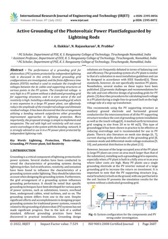
Fig 1: SystemconfigurationforthecomponentsandPV stringunderinvestigation.
International Research Journal of Engineering and Technology (IRJET) e ISSN: 2395 0056
Volume: 09 Issue: 07 | July 2022 www.irjet.net p ISSN: 2395 0072
The system is made up of many arrays (rectangular boxes).EightPVstrings,eachwiththreesetsofpanels,are connectedinparalleltoformonearray.Eachstring'spanels areinterconnectedinseries.Aparallelconnectionbetween thestrings'outputsandaninverterisusedtoprotectthem from surges (SPDs). The inverters are then coupled in parallel on the ac side, and a distribution transformer transmitstheiroutputstothemediumvoltagedistribution system.Lightningrodshavebeeninstalledinthefacilityto safeguard the PV system from a direct lightning hit. The locationsoftheselightningrodsareindicatedbythedotsin the diagram. The circles in the illustration represent the protectionareaforeachlightningrod,whichisdetermined bytheprotectionanglemethodinaccordancewithanIEC standard[12].
All of the PV system's components are safeguarded by choosing the air termination rods' height, installation locations, and number. The PV modules may degrade or sustain irreparable damage as a result of the potential differencebetweentheDCcableandthePVbracketsatthe supportingstructures.Tothebestofourknowledge,there hasn'tbeenmuchdiscussionofthisdamagingprocessinthe literature. It is crucial to comprehend how the grounding configuration influences the transferred voltage. This isso thatengineersmaychoosethebestgroundingdesignforaPV plantbycomprehendingthemechanism.Inthisregard,aPV string a fundamental unit for power production is in depthlyexaminedinthefollowingsections.
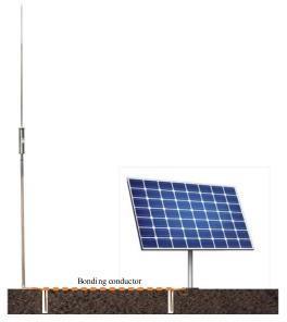
One PV string and one lightning rod are modeled separatelyforthesakeofsimplicity.Thearrangementofthe PVsystemunderconsiderationisshowninFig.2.Numerous PV panels are mounted on three supporting structures to formthePVstring.Thesupportingstructuresarecomposed ofC profilesteelandare4mlong,3mbroad,and3mapart fromeachother.Thesupportingstructuresare3mmtall, standing2maboveand1mbelowthesurface.TheCprofile steel has a width of 4 mm and a thickness of 3 mm. The supportingsupportsaremountedusingthe4mm diameter DC wires of the PV string. These DC wires have SPDs protectingthemandarejoinedtoaninverteratoneend.The lightningrodis7.6metersfromthePVstringclosesttoit. Theground levellightningrodisa10mconductorthatis attachedtoa3mlongverticalgroundingrod.
wirecomponentsmaybefoundinthePVsystems,suchas thewiringinthePVpanels,dccables,lightningrods,andPV supporting structures. In this study, the PV supporting structurescomposedofCprofilesteelaremodeledusingthe noncircularthin wiremodel[22],whereasthedccablesand groundingconductorswithcircularcross sectionarestudied usinganextendedthin wiremodel[18] [23].Duetoitslittle effect on the common modevoltage, the wiring in the PV panelisdisregarded[24].Theextended thin wire model is also used to model thecylindricalconductorthatservesas thelightningrodanditsearthrod.
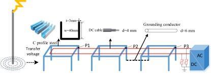
Themodeldescribedin[25]servesasarepresentationof the lightning channel. According to IEC 62305 [26], the channelbasereturnstrokecurrentshouldhaveawaveform of 0.25/100 s and a magnitude of 50 kA. A voltage dependent resistor simulates SPDs. Fig. 3 displays the V I characteristicoftheSPDs.Theworkingareaisdividedinto 150non uniformcellswithsizeof210by210by150meters inthesimulation.Thesmallestcellsizeincloseproximityto theinvestigatedPVsystemis0.20.2m.
Itgraduallyrisesto2mintheydirectionand8minthex andzdirections.Inthesimulation,thelightningchannel's lengthissetto480meters.Sevenperfectlymatchedlayers thatabsorbboundaryconditionsareemployedtoblockout undesirableborderreflections.Thereareatleast28cellsin the empty region between the conductors and absorbing barriers.TheCourant Friedrichs Lewylimitestablisheswhat timestepis being used. Fig. 4depicts thesideviewofthe computationaldomainintheFDTD.Agraphicsprocessing unitTeslaTMK40CGPUComputingAccelerator]isusedto speedupnumericalcomputing.Forthesimplifiedonestring modelgiveninFig.2,thecomputationtimeis2hoursand52 minutes. Fig - 2 V IcharacteristicoftheSPDsmodel(V1=−1500, V2=−1200V,V3=1200V,V4=1500V;R1=R5=0.001 ΩR2=R4=1000Ω,R3=1MΩ).
AsseeninFig.1,several
Theabove mentionedissuesarelookedatusingthethree dimensionalFDTDapproach,whichhasbeenwidelyutilized in lightning electromagnetic pulse and surge simulations [13] [17].Thediscretesecond orderapproximationisused by the FDTD method to solve Maxwell's equations. The repeatedlystaggeredupdatesofthediscretizedelectricand magnetic field components are sampled with a half step offsetinthetimeandspacedomain.
InmanyPVplants,verticalgroundingrodsareusedto ground PV systems at the PV inverters. The PV mounting structures have no separate grounding grid. Becauseaof thesupportingstructuresisburiedintheground,theyare thought of as the system's "grounding electrode." The followingfactorsformthefoundationofthisdesign.Firstoff, itwouldtakealotofmoneytocreateabiggroundinggrid
International Research Journal of Engineering and Technology (IRJET) e ISSN: 2395 0056
Volume: 09 Issue: 07 | July 2022 www.irjet.net p ISSN: 2395 0072
becauseofthebigcoveredareaandremotelocation.ThePV grounding system lacks a unified standard,which is the secondissue.Furthermore,becausethereareindependent lightningrods,lightningisnolongerconsideredaseriousrisk thatcanseriouslyharmPVsystems.
Inthissection,welookedintothelightningovervoltage at various PV system locations when an independent lightningrodwaspresent.Thereisnoadditionalordedicated grounding grid installed; instead, three PV supporting structuresareeachindividuallygroundedusingbrackets.As depicted in Fig. 1, the SPDs at an inverter's input port safeguard the dc wires. Using the model described in the previous section, the transmitted voltage between the supportingstructuresandthedccablesatvariousplacesP1, P2, and P3, as illustrated in Fig. 5, is determined. For comparison,twosoilresistivityvaluesof100and2000mare used.Weassumethatr=10fortherelativepermittivityand r=1fortherelativepermeability.
withinalimitedtimeoscillationatfirst,thenstartstofall.As yougetclosertothesystemgroundingrod,thetimetothe peakislongerandlonger(4.5satpoint1,5.38satpoint2, and6.5satpoint3),comparedtowhenthesoilresistivityis 100m.Withpeakvoltagesof2248kVatpoint1,1002kVat point 2, and 225.9 at point 3, this peak voltage is also significantlyhigherthanthepreviousone.Thisindicatesthat the voltage will have a bigger amplitude and a longer durationwhenthePVsystemisputinalocationwithhigh soilresistance.
Asaresult,thesystem'slightningovervoltageissuewill be more severe than it would be if it were situated somewherewithlowsoilresistivity.Itshouldbeemphasized thattheinductivecouplingfromthecurrentinthelightning rod is mostly responsible for the voltage oscillation that occurswithinthefirstmillisecond.Thegroundpotentialrise atvariousgroundsitesiswhatcausesthegradualincreasein voltage, as depicted in the figure. The soil resistivity is significantlyrelevanttothisvoltage.Thevoltagecausedby thegroundingpotentialriseatvarioussitesisminorwhen thesoilresistivityislow.Therefore,theinductivecoupling effectdominatesindeterminingtheoscillationpeakofthe voltage.However,thevoltagecausedbytheriseinground potential becomes considerable when the soil resistivity reaches2000m.
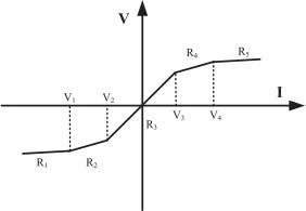
A site with low soil resistivity is indicated by the assumption that the soil resistivityis100m. Thevoltages betweenthePVcablesandthePVbracketsatthreedistinct placesaredepictedinFig.6.Thevoltageatpoint1canpeak at1267kVandoscillatesitswaydownto120kVinlessthan onemicrosecond.Theresidualvoltagelastsforaverylong period and drops off quite gradually. This suggests that a highvoltagehasbeenplacedbetweenthePVcableandthePV bracketforaconsiderableamountoftime.Peakandresidual voltagesatpoint2are842.9and53.5kV,respectively.The peak voltage and residual voltage are 489.9and 12 kV at position3.Thisindicatesthatwhentheobservationpointis movedtothegroundingpointattheinverter,boththepeak voltageandtheresidualvoltagedecrease.
Thesystem'sovervoltagebetweenthedccableandthe PVbracketisalsoevaluatedwhenitisinstalledatalocation withhighsoilmoisturelevelsresistivity.Thesoilcurrently hasaresistivityof2000m.Thevoltagesatthreedifferent sites. It has been noted that the voltage waveform with a 2000msoilresistivityisdifferentfromthatata100msoil resistivity. In this case, the voltage rises to its peak level
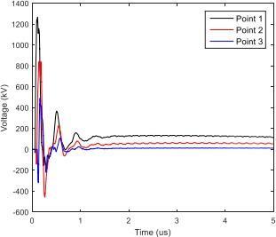
Fig 4: Influenceofthedistance.
ToensurethesafetyofPVsystemsfollowingalightning strike,severalPVplantsincorporategroundinggridsforthe supporting structures. Different grounding grid configurations are described in the literature. The transmittedvoltage between the PV cable and the PV bracket is calculated in this section using a variety of groundinggridconfigurations.Theeffectofsoilresistivityis alsodiscussed.
First,asimplegroundinggridwithseveral horizontal conductorsburiedinthesoilatadepthof1misused.As showninFig.8,theseconductorsareusedtoconnectthePV bracketsandthePVinverterbeneaththeground.
Thevoltagewaveformsatthepreviouslyindicatedthree points.Atpoint1,thehighestvoltageis1250kV,whileat
Fig 3: OvervoltagesinthePVsystemwithoutdedicated groundinggrid(lowsoilresistivity).International Research Journal of Engineering and Technology (IRJET) e ISSN: 2395 0056
Volume: 09 Issue: 07 | July 2022 www.irjet.net p ISSN: 2395 0072
point 2,it dropsto 873.6kV. The peak voltage is further reduced to 527.3 kV at point 3. Compared to systems withoutsuchagroundinggrid,thesevoltagepeaksdonot changesignificantly.Thevoltage,however,degradesmore quicklyandapproacheszeroafter5us.Thesystemwon't experiencepersistentovervoltageasaresult.Thisissothat thereisalowresistancepathfromthePVbracketstothe inverter's grounding rod provided by the buried conductors.
Thesimulationwasalsorunwitha2000mincreasein soilresistivity.ThevoltagewaveformsbetweentheDCcable andthePVbracketareshownatthreeplaces.Incomparison tothecasewithlowsoilresistivity,itisdiscoveredthatthe situation is not as bad. The voltage peaks are 1229 kV at point1,907kVatpoint2,and516kVatpoint3,whichare nearlyidenticaltothosefor100msoilresistivity.Keepin mindthatthevoltagealmostreacheszerowithin2sofrapid voltagedecrease.Thevoltagewithouttheburiedhorizontal conductedisdifferentfromthis.Thus,theovervoltagehasa smallerimpactonthePVsystem.
Amorecomplexgroundinggridischosenforcomparison in order to examine the impact of the grounding grid configuration on the overvoltage in the PV system, as illustrated. A buried conductor mesh is offered in this situation.Theintensitydisplayswaveforms.Unexpectedly, thegroundingmesh,whichhasbeenshowntobeeffectivein loweringthe possibility.Despite any variations within the grounding system, the between the PV wire and the PV bracket,anovervoltageActually,whenthegroundingmesh ispresent,thevoltagesomewhatrisesisusedasopposedto buriedconductors.
TheinvestmentreturnratioofPVpowerplantscanbe significantly increased by lowering the installation and building expenses. No matter if the grounding grid is installedasburiedhorizontalconductorsorameshgrid,the overall investment cost will surely increase. Therefore, a more cost effective strategy is suggested in this section, namelytheadoptionofanairbornebondingnetworkinplace ofburiedconductors.
In this part, the system performance of the suggested techniqueduringalightningstrikeisexamined.Thisthird arrangement's configuration. The horizontal bonding conductorsare used tolink theinverter, three supporting structures, and the higher level of the atmosphere. These cablesarecloselyspacedparallelconductorsthatrunwith theDCcables.
The simulation was run for the bonding network case. The turned out to be a bit unexpected especially from a useful standpoint. Although there is none voltages at each ofthese locations are all on a distinct grounding grid.Considerably diminished in comparison to the outcomes of the other two grounding configurations.
Thisstrategyexhibitsasignificantimprovementwhen thePVsystemisputinalocationwithhighsoilresistivity thepeakvoltagesatpoints1and3arefurtherdecreased when compared to the case of the low soil resistivity, falling to964.1and222kV,respectively.Thepeakvoltage at point 2 is raised to 812.1 kV, however. When the soil resistivity is high, the depreciation of these voltages happensmorequickly.
It has been shown that a grounding grid with buried conductorscangreatlylowerthelightningovervoltageina PV array. However, this approach can occasionally be challengingtouse,particularlyinareaswithrockyterrain, mountains,andstiffsoil.However,asthecostofPVpanels andinverterscontinuestofall,PVpowerplantinvestorsare becoming increasingly concerned about installation and constructioncosts.
In this section, we assess how a stratified soil with horizontallayersaffectstheprotectiveeffectundervarious groundingconfigurations.Considerationisgiventosoilwith twolayers.Thevaluesh1=1mandh2=9m,respectively, denotethedepthsofthetopandlowerstrata.Thetopand lowerlayersoilresistivitiesaredenotedbyh1=100mand h2 = 500 m, respectively. The voltages at three sites for various grounding configurations. The voltages beneath a uniformsoil(100m)arealsoshownforbettercomparison. Compared to the outcomes of the other two grounding configurations.
Tomorethoroughlyresearchtheimpactofsoilstructure onthesuggestedstrategy.Differentsoilresistivitiesandsoil structuresaretakenintoconsideration.Thehigherlayeris mostly responsible for the overvoltages between the DC cableandthePVsupportingstructure.Onlyasmallamount of the overvoltage is influenced by the bottom layer's soil resistivity.Ifthesuggestedstrategyisused,andthetoplayer is deep enough, the overvoltage won't be affected by the
International Research Journal of Engineering and Technology (IRJET) e ISSN: 2395 0056
Volume: 09 Issue: 07 | July 2022 www.irjet.net p ISSN: 2395 0072
lowerlayer'ssoilresistivity.
By using this equipotential bonding technique, as demonstratedinearliersituations,thelightningovervoltage betweenthecableandthePVbracketmaybesignificantly decreased. The outcomes are far superior to those in the systemwithagroundingmeshandfarsuperiortothosein thesystemwithoutaspecializedgroundinggrid.Sensitivity analysisisdoneinthissectiontoseehowalternativesystem configurations will affect the overvoltage between the PV cableandthebracket.
Toproperlychannelthelightningcurrentintotheground, a 4 by 4 m square. The lightning rod has a grid for grounding.A2mby2m.Itisburiedthreemetersbeneath thesurfaceoftheland.Themimicrywasdonetogaugethe voltagesatthreedifferentlocations.Itisevidentinthethe voltagesbetweenthewiresandthebracketsinthetableThe PV system appears to remain unchanged following a groundinggrid.isusedasalightningrod.
equipotentialbondingconductorispresentinthisinstance inthe midstof thetwoDCcables.Duetothesmallerloop area between thecables and the bonding conductor, it is discoveredthatthevoltagesatallplacesarelowerthanthey wouldbewiththebondingconductorsgivenatonesideof thedccables.
This section addresses the problems of adopting a condensed PV model and neglecting the neighboring PV stringwhenassessingtransmittedvoltages.
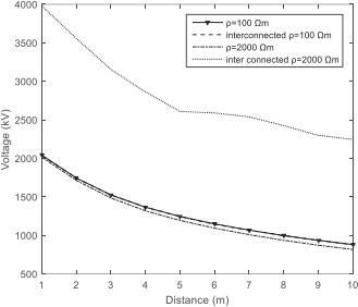
Somestandardsprescribetheinterconnectionofadjacent groundingsystems.Forinstance,accordingto,independent lightningrodsshouldbelinkedtoabuilding'sgroundinggrid if the distance between them is less than 3 meters. The lightningprotectionsystemmustbelinkedwithinwithin3.6 metersofanygroundedconductorsthatmighthelpprovide achannelforlightningcurrentsinoronabuildinginorder to create a common ground potential, according to NFPA 780[28].Thetwocriteriamentionedabovearemostlyfor homes. To further research how distance affects the lightningovervoltage. For comparison, several distances between the grounding grid of the PV system and the independentlightningrodareused.Thepeakvoltagefalls offmorequicklyinthefirstfewmetersandthengradually beyondthat.Noofthedistance,theconnectorhasthesame impactonthetransmittedvoltageaspreviouslyindicated.
Choosing the appropriate equipotential connection position can further decrease the overvoltage. The
Throughgalvanizedaluminumwires,thePVcellsofeach panelarelinkedinseries.Overvoltagewillbecreatedinthe loopthegalvanizedaluminumwiresmakeuponalightning strike.BypassdiodesinthePVpanelmightfailasaresultof this overvoltage. Additionally, the voltage between the positive and negative dc cables will be impacted by the overvoltage in each panel. As a result, it is impossible to simplifythewiretopologywhenanalyzingthevoltageinthe bypassdiode.Asaresult,itisimpossibletosimplifythewire topology when analyzing the voltage in the bypass diode. Additionally,ifthePVpanel'swiringlayoutismadesimpler, the assessment of the voltage between the positive and negativeDCcablesmaybebiased.However,therewon'tbe muchofabiaswhenanalyzingovervoltagescausedbythe groundpotentialrisebetweenthegroundingstructure(PV brackets) and the dc cables when using a basic model. To demonstrate that it is rational to assess the overvoltage betweenthemetalframeusingasimplerwirestructureand thedccable,whichisemulatedwithvariousloopregionsfor comparison(the+/ dccables'spacingvary)
There are several PV strings in a PV plant. Due to the close proximity of the neighboring strings, inductive and conductivecouplingsbetweenparallelPVthreadsmayhave animpactonthecomputation'soutcomes.Inthissection,the impactofthenearbystringsisexamined.Inthesimulation,it is assumed that the two strings are 3 m apart. The transferredvoltage in the PV system when a nearby PV string. The voltage amplitudes under each grounding configuration with/without a nearby PV string are also displayed in the table for easier comparison. This table showsthatwhenthenearbyPVstringispresent,thevoltage amplitude will decrease in each grounding configuration. However, theconclusion reachedinearliersections that establishingabondingnetworkintheairispreferabletothe othertwoarrangements isunaffectedbytheexistenceof thenearbystrings.
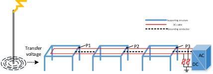 Fig Systemwithhorizontalbondingnetworkintheair
International Research Journal of Engineering and Technology (IRJET) e ISSN: 2395 0056
Volume: 09 Issue: 07 | July 2022 www.irjet.net p ISSN: 2395 0072
ThePVsystem'sgroundingconfigurationisaproblem thathasn'tyetreceivedmuchattentionfrominternational standards.Engineerstypicallyincreasethequantityofburied conductors, decrease the mesh size, and choose an appropriate grounding grid arrangement when creating a lightningprotectionsystemforaPVsysteminordertolower the resistance of the grounding grid and homogenize the potentialdistribution.Thesetechniquesareexpensive,andit isunknownhoweffectivetheyareinprotectingPVplants againstseparatelightningstrikes.Thesystememployinga dedicatedgroundinggrid,asadvisedbythemajorityoflocal standards and manufacturers, can reduce the lightning overvoltage between the dc wire and the PV bracket, according to the results of this article's research. By supplying bonding conductors running in parallel with dc cables in the air, it is possible to significantly reduce the overvoltage.Byputtingthebondingconductorsinthemidst oftwosuspendedDCwires,theovervoltagemaybefurther decreased. Thisapproachislesscostly,simplertouse,andevenmore effective in blocking lightning than grounding mesh. The performanceoflightningprotectionisnotworsenedbysoil withincreasedresistivitythankstothebondingnetwork.On the other hand, when the soil resistivity is high, the PV systemwillexperiencelessresidualvoltage.Thismeansthat whenlightningprotectionisaproblem,thesiteselectionofa PV plant will not be constrained by the soil resistivity. Furthermore, the voltage between the dc wire and the PV bracket is little affected by the way a lightning rod is grounded.Consequently,asophisticatedgroundingsystem for the lightning rod is not required. Some standards advocateconnectingalightningrod'sgroundterminaltothe grounding grid of a photovoltaic system. When the soil resistivity is high, however, such connectivity may significantlyincreasethelightningovervoltagebetweenthe DCwireandthePVbracket.Evenwithlowsoilresistivity, theproblemwon'tgetanybetter.Thepurposeofconnecting twogroundingsystemsistopreventelectricshockduringa faultsituationoralightningstrike.Thismethodistypically used in residential structures or installations of a similar kind.Ifthedistance betweenthelightning rodandthe PV systemistoogreatforonepersontotouchbothatonce,then suchaconnectiondoesnotapplytothePVplant.
The author is very great thankful to Dr. M. K. Elango Director and Professor & Dr. P. Aravindan HoD/EEE & sincere thanks to all faculty members of our EEE Department for their valuable suggestions, kind co operations and constant encouragement for successful completion of the paper. N. Rajasekaran for her guidance and giving valuable suggestions, advice to improve the paper.
[1] GuideforSafetyinACSubstationGrounding,IEEEStd.80 2000,2019.
[2] R Schaerer and D Lewis, Large utility scale photovoltaicsolarpowerplantgroundingsystemsafety design generalpracticesandguidance,‖inProc.IEEE PowerEnergySoc.Gen.Meeting,2018pp.1 5.
[3] J Ma and F P Dawalibi, Grounding analysis of a solar powergen□erationfacility,‖inProc.Asia Pacific PowerEnergyEng.Conf.,2010,pp.1 4.
[4] Z G Datsios and P N Mikropoulos, Safe grounding systemdesignforaphotovoltaicpowerstation,‖2012.
[5] ProtectionAgainstLightning Part3:PhysicalDamageto Structures and Life Hazard, International Electro technicalCommission.IEC62305 3,2015.
[6] J Birkl and E Shulzhenko, Investigation of lightning current distribution in a large scale earth termination system of photovoltaic powerplant,‖ in Proc.34thInt.Conf.LightningProtection,2018,pp.1 7.
[7] P H Pretorius, Loss of equipotential during lightning ground poten□ tial rise on large earthing systems,‖ in Proc. IEEE Int. Symp. Electro magn. Compat.,IEEEAsia PacificSymp.Electromagn.Compat., 2018,pp.793 797.
[8] C. A. Charalambous, N. D. Kokkinos, and N. Christofides, External light ning protection and grounding in large scale photovoltaic applications,‖ IEEE Trans. Electromagn. Compat., vol. 56, no. 2, pp. 427 434,Apr.2013.
[9] A. Formisano, C. Petrarca, J. C. Hernndez, and F. J. Muoz Rodrguez, Assessment of induced voltages in commonanddifferential modeforaPVmoduledueto nearbylightningstrikes,‖IETRenew.PowerGener.,vol. 13,no.8,pp.1369 1378,2019.
[10] Y. Zhang, H. Chen, and Y. Du, Lightning protection designofsolarphotovoltaicsystems:Methodologyand guidelines,‖Elect.PowerSyst.Res.,vol.174,2019,Art. no.105877.
[11] I. Naxakis, G. Mihos, S. Pastromas, and E. Pyrgioti, Examiningtheoperationofthegroundingsystemofa PV installation,‖ in Proc. IEEE Int. Conf.HighVoltage Eng.Appl.,2018,pp.1 4.
[12] ProtectionAgainstLightning Part1:GeneralPrinciples, IEC62305 1,2010.
[13] Y Du, B Li, and M Chen, Surges induced in building electricalsystemsduringalightningstrike,‖ Elect.PowerSyst.Res.,vol.139,pp.68 74,2016.
[14] A. Tatematsu and T. Noda, Three dimensional FDTD calculation of lightning induced voltages on a multiphase distribution line with the light□ ning arrestersandanoverheadshieldingwire,‖IEEETrans.
International Research Journal of Engineering and Technology (IRJET) e ISSN: 2395 0056
Volume: 09 Issue: 07 | July 2022 www.irjet.net p ISSN: 2395 0072
Electromagn.Compat.,vol.56,no.1,pp.159 167,Feb. 2014.
[15] A. Tatematsu, S. Moriguchi, and T. Ueda, Switching surgeanalysisofanEHVair insulatedsubstationusing the3 DFDTDmethod,‖IEEETrans.PowerDel.,vol.33, no.5,pp.2324 2334,Oct.2018.
[16] B.U.Musa, W. H. Siew, and M. D. Judd, Computation oftransientelectromagneticfieldsduetoswitchingin high voltagesubstations,‖IEEETrans.PowerDel.,vol. 25,no.2,pp.1154 1161,Apr.2010.
[17] R Xiong, B Chen, B H Zhou, and C. Gao, Optimized programs for shaped conductive backfill material of groundingsystemsbasedontheFDTDsimulations,‖ IEEETrans.PowerDel.,vol.29,no.4,pp.1744 1751, Aug.2014.
[18] Y Taniguchi,Y Baba,N Nagaoka,andA Ametani, An improved thin wire representation for FDTD computations,‖IEEETrans.AntennasPropag.,vol.56, no.10,pp.3248 3252,Oct.2008.
[19] Y Baba,N Nagaoka,andA Ametani, Modelingofthin wiresinalossymediumforFDTDsimulations,‖IEEE Trans.Electromagn.Compat.,vol.47,no.1,pp.54 60, Feb.2005.
[20] T. Noda and S. Yokoyama, Thin wire representation in finitedifferencetimedomainsurge simulation,‖IEEETrans.PowerDel.,vol.17,no.3,pp. 840 847,Jul.2002.
[21] R Holland and L Simpson, Finite difference analysis of EMPcouplingtothinstrutsandwires,‖ IEEETrans.Electromagn.Compat.,vol. 23,no.2,pp. 88 97,May1981.
[22] B.Li,Y.Du,andM.Chen, AnFDTDthin wiremodelfor lossywirestructureswithnoncircularcrosssection,‖ IEEETrans.PowerDel.,vol.33,no.6,pp.3055 3064, Dec.2018.
[23] Y Du, B Li, and M Chen, The extended thin wire model of lossy round wire structures for FDTD simulations,‖IEEETrans.PowerDel.,vol.32,no.6,pp. 2472 2480,Dec.2017.
[24] K Yamamoto, J Takami,and N Okabe, Overvoltages on DC side of power conditioning system caused by lightning stroke to structure anchoringphotovoltaic panels,‖Elect.Eng.Jpn.,vol.187,no.4,pp.29 41,2014.
[25] Y. Baba, S. Miyazaki, and M. Ishii, Reproduction of lightning electro□ magnetic field waveforms by engineering model of return stroke,‖ IEEE Trans. Electromagn.Compat.,vol.46,no.1,pp.130 133,Feb. 2004.
[26] Protection of Structures Against Lightning: Part I GeneralPrinciples,IEC62305 1,2010.
[27] GB50169: Code for construction and acceptance of groundingconnectionelectricequipmentinstallation engineering,2016.
[28] NFPA 780: Standard for the Installation of Lightning ProtectionSystems,Nat.FireProtectionAssoc.,Quincy, MA,USA,2020.
(Optional not mandatory )
RPrabhu PGScholar@KSRCT, Tiruchengode

Area of Specialization: Power Systems Website: https://Scholar.google.com/citatio ns?user=6ATiqxkAAAAJ&hl=en Facebook: https://www.facebook.com/prabh uravi.prabhuravi.3
AIlakiya, PGScholar@KSRCT, Tiruchengode
Area of Specialization: Power Systems