International Research Journal of Engineering and Technology (IRJET) e ISSN: 2395 0056
Volume: 09 Issue: 07 | July 2022 www.irjet.net p ISSN: 2395 0072
International Research Journal of Engineering and Technology (IRJET) e ISSN: 2395 0056
Volume: 09 Issue: 07 | July 2022 www.irjet.net p ISSN: 2395 0072
Barani M1 , Rakul P R2 , Mohammed Thoufeek3, Dr. M.A. Vinayagmoothi4
1 2 3 Student, Dept. of Mechanical Engineering, Kumaraguru College of Technology, Tamil Nadu, India 4Assistant Professor, Dept. of Mechanical Engineering, Kumaraguru college of Technology, Tamil Nadu, India ***
Abstract The Steering system is one of the vital subsystems of a vehicle which provides directional control and stability. In this project we are designing a steering system for an All Terrain Vehicle. An All Terrain Vehicle (ATV) is a vehicle that can travel on all different terrains. As a result, the steering system is designed for the worst case scenario, providing maximum directional control, pure rolling motion to the wheel, and the minimum possible turning radius. The main aim of this paper is to design a efficient steering system for an ATV.
Key Words: ATV,SteeringSystem,Ackermanngeometry,RackandPinion,Design
Thesteeringsystemisasetofassembledcomponentsthatguidesthevehicletofollowadesiredcoursebasedonthedriver's input.Thegoalofthesteeringsystemistoprovidedirectionalcontrolforthevehicle,toreducesteeringeffortandofferproper roadresponsetothedriver.
TheAckermansteeringsystemisdesignedusingafour barlinkagemechanisminwhichseverallinkagesmoverelativeto oneanotheranddirectthevehicleinaspecificdirection.Thissystemisusefulinsharpcornerssinceitreducessteeringeffort andfacilitatesmaneuverability.
Incomparisontoothersteeringmechanisms,therackandpinionmechanismisidealduetotheobviousbenefitsofsimple design,easeofmanufacturing,significantlyreducedspacerequirements,andcost effectiveness.
Thepinionofarackandpinionsystemmesheswiththepinion,whichisfastenedtotheendofthesteeringshaft.The pinionisrotatedbyrotatingthesteeringwheel.Themovementofrackisresponsibleforturningofwheelsthroughsteering linkages.
Thefollowingliteraturesurveygivesapreviewglimpseofourworkinthisresearchrelatedtodesignofsteeringsystemin anATV.
Mohan poojari et al. [1]: Designeda2 DTurningradiusmechanismbyusingCatiaV5R21consideringtheacquiredbasic parameterracklengthsteeringarmlengthandotherparametersarechangedtoobtaindifferentturningradiusandAckermann percentagevalues.
William F. Milliken and Douglas L. Milliken [2]: InthebookofRaceCarVehicledynamicsItisshownthatifthewheel steersautomaticallywhenitturnsoverabumpordrooporwhenthevehiclerollsinaturnthevehiclewilltravelinapaththat driverdidnotselect.Soitisgoodtokeepzerobumpsteer.
Akshay Pawar and Suraj Zambare [3]: WheelbaseandTrackWidtharedecidedconsideringthesuspensiongeometry, handlingandstabilityofthevehicle.Kingpinoffsetwasdecidedbyconsideringthewheelassemblyandcastorangleselectedso thatitgivesstraightlinestabilityandoptimumself returningactionforbetterhandling.Positionofrackischosenbyconsidering pedalpositionandtoavoidsignificantamountsofbumpsteer.
Shylaen S Keshwani and A. M. Surendra Kumar [4]: TomakecalculationsimpleraC Programwascodedwhichcalculates varioussteeringvaluesneededsuchasAckermannangle,TieRodLength,SteeringRatioetc.Thisprogramwassimulatedunder differentAckermannangle,anditwasinferredthatwhentheAckermannangleincreasestheouterwheelturnslesser,which givesthebettersteeringresponse,andinputvariabilityincreaseshenceitgivessmoothdriving.
Nitish Malik et al [5]: Increasedthediameterofsteeringwheeltoreducethesteeringeffortbecausethedrivereffortto rotatethesteerhasbeenincreaseduponreducingthesteeringgearratio.
2022, IRJET | Impact Factor value: 7.529 | ISO 9001:2008 Certified

International Research Journal of Engineering and Technology (IRJET) e ISSN: 2395 0056
Volume: 09 Issue: 07 | July 2022 www.irjet.net p ISSN: 2395 0072
Amit Kumar Shakya et al. [6]: TominimizethebumpsteertierodmustbeparalleltoSuspensionA Armssothatduring bumptheInstantaneouscenterofthetierodmeetstheinstantaneouscenteroftheA Armsatinfinity.Inthismanner,thearc travelledbythetierodsandthearmswereequidistanttoeachotherduringsuspensiontravel,andnoforcewasgeneratedalong theracktoproducebumpsteer.
Kshitij N Sable et al. [7]: Thecalculatedvalueswerevalidatedusinglotussharksoftwaretochecktheproperfunctioningof suspensionsystemsandthenthedesigningofcomponentsweredoneinCADSoftwareCATIAV5R21.Allthecomponentsare analysedtotherealworldusingFiniteElementAnalysis
Prashant L Agrawal et al. [8]: Itwasmentionedthatthelengthofthesteeringrackisdirectlyproportionaltotheangleof thesteeringwheelandinverselyproportionaltotheaverage turningradiusofthevehicle.
Sandeep Chaudhary et al. [9]: Whileavehicletakingaturntheouterwheeltravelsmoredistancethantheinnerwheeli.e., innerwheelmakeshigheranglethantheouterwheel.SoHigherthesteeringanglesmallerwillbetheturningradius.
Element C Si Mn P S Cr Mo Ni
Content (%) 0.10 0.20 0.10 0.35 0.50 1.00 0.040 (Max) 0.040 (Max) 0.75 1.25 0.08 0.15 1.00 1.50
Table 1: ChemicalCompositionofEN 353
Mechanical Properties Density (gm/cm³)
Young’s Modulus (Gpa)
Poisson’s Ratio Yield Strength (Mpa)
Compression strength (Mpa)
Ultimate Tensile strength (Mpa)
Value 8.08 190 0.26 440 550 550
Table 2: MechanicalPropertiesofEN 353
SinceEN353hasgoodductilityandfatiguestrengthweuseitforrackandpinion.
Steeringsystemshouldbedesignedinsuchamannersothat Itshouldbeaccurateandeasytohandle, Steeringeffortshouldbeminimum, Roadshocksshouldnotbetransferredtodriverand
Itshouldprovidepurerollingmotiontowheel
2022, IRJET | Impact Factor value: 7.529 | ISO 9001:2008 Certified
International Research Journal of Engineering and Technology (IRJET) e ISSN: 2395 0056
Volume: 09 Issue: 07 | July 2022 www.irjet.net p ISSN: 2395 0072
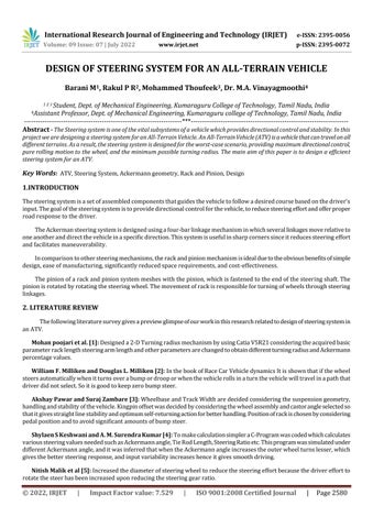
Fig -1:DesignMethodology
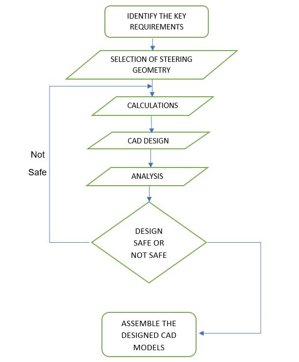
Tractionisanimportantfactorinoff roadracingascomparedtospeed.WechooseAckermannsteeringgeometrysinceitgives highstabilityatlowerspeed.Becauseoftheterrain,thisgeometryissuitableforBAJAvehicleswithaspeedlimitof60kmph.
Fig 2:SchematicDiagramofAckermannSteering[3]
2022, IRJET | Impact Factor value: 7.529 | ISO 9001:2008 Certified Journal
International Research Journal of Engineering and Technology (IRJET) e ISSN: 2395 0056
Volume: 09 Issue: 07 | July 2022 www.irjet.net p ISSN: 2395 0072
AccordingtotheAckermannprinciple,theextendedaxesofthesteeringarmshouldmeetatthecentreoftherearaxle. Whenavehicleisturning,theconditionofperfectrollingisreachedwhentheextendedaxisofthefrontwheelsandthe rearaxismeetatapoint.Thispointiscalledinstantaneouscentreofthevehicle.Theinnerwheeldeflectsmorethanthe outerwheelwhileavehicletravelsalongacurvedpathtopreventskiddingwhilecornering
TrackWidth(mm) 1219.2
Wheelbase(mm) 1320.8
LocktoLock 1.25
InnerWheelAngle (Deg.) 48
Distancebetween KingpinCenter Center (mm)
1122.68
GroundClearance(in) 12
Table 3: InitialParametersforsteeringdesigncalculations
Ackermann angle
tanα=kingpin kingpincentredistance/2x(Wheelbase)
α=tan 1 (1122.68/2x52x25.4)
α=23.03°θ
Maxinnerwheelangle,Assume,θ=48°
ByAckermanncondition
Cot(Φ) cot(θ)=Trackwidth/wheelbase
(Φ)=28.74°So=29°(Maxouterwheelangle)
TurningRadiusoffrontinnerwheel,Ri=wheelbase/Sin(θ) (Trackwidth K.k)/2
TurningRadiusoffrontouterwheel,Ro=Wheelbase/Sin(θ) (Trackwidth k.K)/2
Ri=1729.50mm,Ro=2698.59mm
Turning Radius (Vehicle)
R=(Ri+Ro)/2=2.2m
Ackermann percentage
Ackerman%=Si/Ackermanx100
Ackerman=tan 1 (Wheelbase/(tan(Φ)*Trackwidth))
© 2022, IRJET | Impact Factor value: 7.529 | ISO 9001:2008 Certified Journal
International Research Journal of Engineering and Technology (IRJET) e ISSN: 2395 0056
Volume: 09 Issue: 07 | July 2022 www.irjet.net p ISSN: 2395 0072
Ackermanpercentage=101%(>100%)oversteer (Assumelocktolocktobe1.25revolution)
Locktolock=SteeringWheelangle/360°
Steeringwheelangle=1.25x360°=450°
Thesteeringwheelmustberotatedabout450°
SteeringRatio=steeringwheelangle(Fulllockononeside)/Innerwheelangle =225/48°=5
Steeringratio=5:1
Rack travel
Steeringratio=steeringwheeltravel(fullrotation)/Racktravel
5=(2*π*(5*25.4)*540)/360/Racktravel
∴Racktravel=188.435mm(full)
Ononeside,racktravel=94.2mm
∴Diameterofsteeringwheel
Steeringratio=steeringwheelcircumference/pinioncircumferences(or)
Radiusofsteeringwheel/Radiusofpinion
5=5*25.4/r
r=24mm
d=48mm(pinion)
No of teeth in pinion
Assumemodule=2*m=D/T∴T=D/m=48/2=24
Gearratio=540°/360°=1.25
Gearratio=Numberofteethinrack/Numberofteethinpinion1.25=N/18
Noofteethinrack=30
ImporttheCalculatedvaluesinLotussharksoftwaretocheckthesuspensioncharacter.
Aftergettingthesystemaimsclear,thesteeringiterationsweredoneinLotusSharksoftware.Someofthepredetermined parametersarelistedintheabovetable.
2022, IRJET | Impact Factor value: 7.529 | ISO 9001:2008 Certified
International Research Journal of Engineering and Technology (IRJET) e ISSN: 2395 0056
Volume: 09 Issue: 07 | July 2022 www.irjet.net p ISSN: 2395 0072
Fig 3:LotussharkInterface
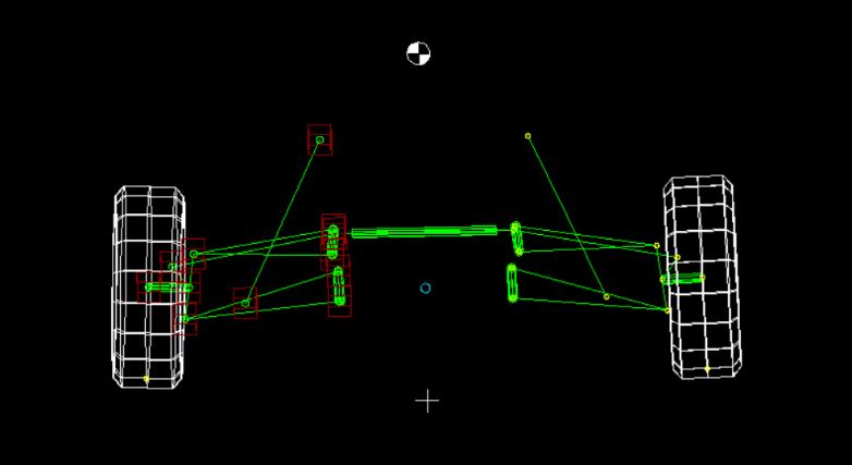
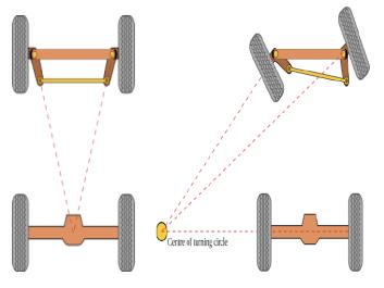
Fig 4:WheelTravelinBumandDroop
AfterseveraliterationsinLotussharksoftwarefinalparametersfordesigningthesteeringsystemwerementionedbelow PARAMETERS
DIMENSIONS
STEERINGMECHANISM RACKANDPINION
ACKERMANNANGLE 23.03 STEERINGARMLENGTH 90mm INNERWHEELLOCKANGLE 48Deg OUTERWHEELLOCKANGLE 29Deg STEERINGRATIO 5:1
ACKERMANNPERCENTAGE 101%
TYPEOFSTEERING Oversteering
STEERINGARMLENGTH 91mm
Table 4: Final
SinceAckermannPercentagegreaterthan100%ThetypeofsteeringwillbeOversteering.Oversteerisatendencyforcarsto turnsharperthanthedriverintended,helpingthetiresgripsharpcorners.
2022, IRJET | Impact Factor value: 7.529 | ISO 9001:2008 Certified
International Research Journal of Engineering and Technology (IRJET) e ISSN: 2395 0056
Volume: 09 Issue: 07 | July 2022 www.irjet.net p ISSN: 2395 0072
International Research Journal of Engineering and Technology (IRJET) e ISSN: 2395 0056
Volume: 09 Issue: 07 | July 2022 www.irjet.net p ISSN: 2395 0072
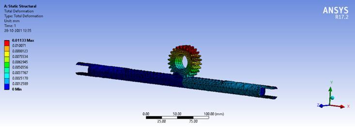
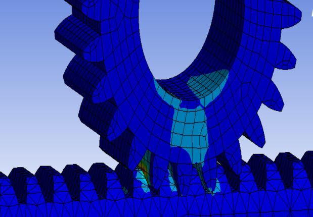
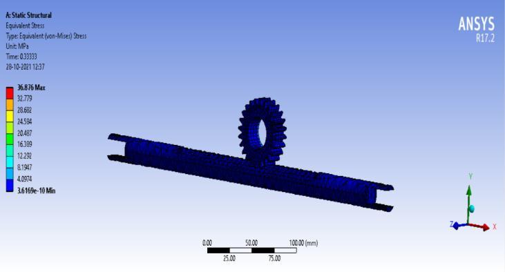
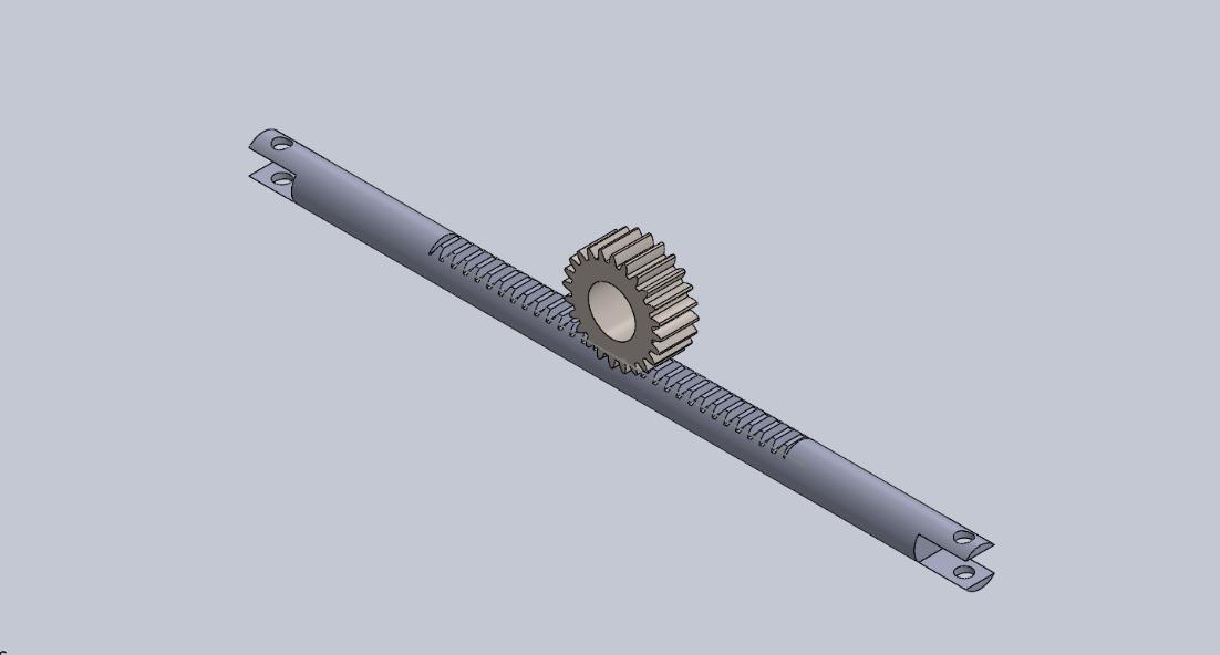
RackPinion
MAXIMUMDEFORMATION=0.01133mm
MAXIMUMSTRESS=36.876Mpa
Factorofsafety=8.1
ThedesignisSafe
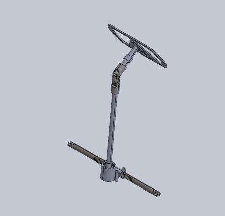
Fig 8:AssemblingofCADModels
ThesteeringsystemplaysanimportantroleintheoverallperformanceofAllterrainvehicles.Thisresearchpaperconcluded bypresentingacompletedesignmethodologyaswellasresultingoptimaldesignsthatcanbemanufacturedforthegivenreal timecondition.Itcanbeusedinoff roadingvehicles.Thefollowingconclusionsareobserved:
Thesteeringhasbeendesignedtoproduceminimumturningradiusof2.2mwith101percentage.Asteeringratioof5:1is achievedalongwithlowsteeringeffort
[1] M.Poojari,B.S.Shreyas,R.Muddaiah,A.Raj,andB.S.Babu,“Design,analysisofsteeringsystemandfront suspensionforanElectricAll Terrainvehicle,”in Materials Today: Proceedings,2021,vol.46,pp.2848 2857.doi: 10.1016/j.matpr.2021.03.102.
[2] “WillamF.MillikenandDouglasF.MillikenRaceDynamicsVehicleDynamics”.
[3] Akshaypawar,andSurajZambare,“DesignofSteeringSystemforAllTerrainVehicle,”2018.
[4] S.S.KeshwaniandA.M.SurendraKumar,“REVERSEENGINEERINGOFSTEERINGSYSTEMWITHDEVELOPED EQUATIONFORSTEERANGLE,”2012.
[5] MalikN,AgarwalPandRajputA,“DesignandPerformanceOptimizationoftheSteeringSystemofavehicle,” Trans Stellar, 2017.[Online].Available:www.tjprc.org
[6] V.Saini,S.Kumar,A.KumarShakya,andH.Mishra,“DesignMethodologyofSteeringSystemforAll Terrain Vehicles,” International Research Journal of Engineering and Technology,2017,[Online].Available:www.irjet.net
[7] M.Kshitij et al.,“Design&AnalysisoftheSteeringSystemforAll TerrainVehicle,”2019.[Online].Available: www.ijsrd.com
[8] H.H.KumarB,C.Byrappa,andA.Professor,“ModelingFiniteElementAnalysisAndWeightOptimizationSteering Arm,”2012.[Online].Available:www.ijedr.org
© 2022, IRJET | Impact Factor value: 7.529 | ISO 9001:2008 Certified Journal
International Research Journal of Engineering and Technology (IRJET) e ISSN: 2395 0056
Volume: 09 Issue: 07 | July 2022 www.irjet.net p ISSN: 2395 0072
[9] P.L.Agrawal,S.S.Patel,andS.R.Parmar,“DesignandSimulationofManualRackandPinionSteeringSystem,”vol. 2,2016,[Online].Available:www.ijsart.com
[10] S.Chaudhary,G.K.Kantak,P.Sharma,andH.Mathur,“DesignAnalysisandFabricationofM BAJAATV2020,”2020. [Online].Available:www.erpublication.org

Barani M
HeispursuingthirdyearBachelor MechanicalinKumaraguruCollege ofTechnology,Coimbatoreandhe is captain of Electrical Baja Team E BLITZfortheyear2022 2023
Rakul P R
HeispursuingthirdyearBachelor MechanicalinKumaraguruCollege ofTechnology,Coimbatore
Mohammed Thoufeek M
HeispursuingthirdyearBachelor MechanicalinKumaraguruCollege ofTechnology,Coimbatore


2022, IRJET | Impact Factor value: 7.529 | ISO 9001:2008 Certified Journal