International Research Journal of Engineering and Technology (IRJET)

e ISSN: 2395 0056 p-ISSN: 2395-0072 Volume: 09 Issue: 07 | July 2022 www.irjet.net
International Research Journal of Engineering and Technology (IRJET)
e ISSN: 2395 0056 p-ISSN: 2395-0072 Volume: 09 Issue: 07 | July 2022 www.irjet.net
1Professor, Dept. of Mechanical Engineering, Mangalam College of Engineering, Kerala, India 686631 2345Btech students, Department of Mechanical Engineering, Mangalam College of Engineering, Kerala, India 686631 ***
Abstract Epoxy resin is widely used in engineering applications due to its high elasticity and light weight. However, their low thermal stability and wear resistance limits their usage at high sliding velocities and loads. The mechanical properties and thermal stability of a machine elementsubjectedtofrictionandwearisveryimportant.Filler materials are introduced to composite matrixes to improve their mechanical, thermal or tribological properties. The propertiesoftheepoxycompositesarehighlyinfluencedbythe type of reinforcement like graphene, single walled carbon nanotubes (SWCNTs), double walled carbon nanotubes (DWCNTs),multi walledcarbonnanotubes, nanoclays,nano silica, carbon nano fibers, etc., to increase the strength and modulus of composites. As variety of combinations of composites are possible by choosing the right mixture of materials for matrix and reinforcement to obtain optimized composite properties. In this Paper, reduced Graphene nanoparticlescompositeswithdifferentweightproportionsof reduced GnP is fabricated by solution casting technique. Mechanical properties are evaluated as per ASTM test standards and sliding wear test is performed following a designofexperimentapproach.
Composite materials are the combination of two or more materials which are different in form and chemical composition.Theseconstituentmaterialshaveparticularly different chemical or physical properties, and they are dissolvedtocreateamaterialwithpropertiesdifferentfrom theindividualelements.Withinthecompletedstructure,the individualelementsremaindistinctanddistinct,separating the composites from mixtures and solid solutions. Compositesarecomposedoftwophases,thematrixphase whichprovidesthebulkformtothecompositelikemetals, ceramics,polymerandthedispersedphasewhichreinforces thematrixphaseandcanbeintheformoffibres,particlesor flakes. Filler materials are materials that are added to the composite to enhance desired properties that might not otherwise be achieved by the reinforcement and matrix ingredientsalone.Compositematerialsarebeingdeveloped toreplaceconventionalmaterialsformanyreasonssuchas higher strength, better fracture toughness, good thermal resistance, low price etc Polymer composites are polymer materialswithareinforcementinwhichthepolymerworks
as a matrix resin that penetrates the reinforcement knots andbondstoreinforcement.Thesecompositesareadvanced materialsthathavehighstrengthatlowweight,whichmake them usable at various applications like automobile, aerospace and household appliances. The decision of the materialforspecificapplicationsdependonvariablessuch asmaterialcost,thickness,quality,andworkingconditions. Polymer composites used in sliding conditions are commonlyusedinlowenergytransfer.Lightweightpolymer matrixcompositesarethemostsuitablematerialsforweight sensitive application in the aerospace and automobile industries.Polymercompositesreplacetraditionalmetaland ceramic materials to make high strength and low conductivityapplicationslikepumpwearring,bushings,line shaft bearings, interstage bushings and pressure reducing bushings. Epoxy resins are the most commonly used thermoset plastic in polymer matrix composites which do notgiveoffreactionproductswhentheycureandthushave lowcureshrinkage.Epoxycompositesareatypeofpolymer materialthatusesanepoxyresintocreateapolymermatrix reinforced with fibers or other fillers. This allows for the constructionoflong lastingpartswithveryhighpower to weightratios.
Reduced Graphene nano platelets was synthesized from graphene oxide. The 99.8% pure graphite flakes was received from Alfa Asear, USA. Concentrated sulfuric acid (H2SO4),phosphoricacid(H3PO4),hydrochloricacid(HCl), hydrogen peroxide(H2O2), potassium permanganate (KMnO4), ethanol, N,N dimethylformamide (DMF) were procuredasanalyticalgradefromS.D.Finechemicals,India. Theanalyticalgradediglycidyletherofbisphenol A(DGEBA) (LapoxL 12,AtulLtd,India)wasusedasthematrixmaterial, andN,N bis(2 aminoethyl)ethane 1,2 diamine(LapoxK 6, AtulLtd.,India)wasusedasahardener,andresinwasmixed withhardenerintheratioof10:1.
Reduced GnP is used as the filler material in this investigation. It is produced through the servothermal reductionmethodwhereDimethylformamide(DMF)isused as the solvent. This particulate filler is thoroughly mixed withtheepoxyresinindifferentweightproportions(0,0.25,
International Research Journal of Engineering and Technology (IRJET)
Volume: 09 Issue: 07 | July 2022 www.irjet.net
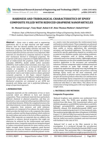
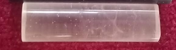
o0.5, 0.75, 1 wt. %). The rGnP is dispersed in DMF and heated under constant pressure and added in different concentrationinepoxy.Thedoughwasthenslowlypoured intothemouldofdifferentshapes,coatedbeforehandwith silicone releasing agent. These were left to cure for 24 h after which the moulds were broken and specimens were released.Thensamplesarecutinto3cmlongcylinderswith 8mmdiametertoconducthardnessandslidingweartests.
e ISSN: 2395 0056 p-ISSN: 2395-0072
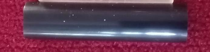
testisperformedprimarilybyatestforce,commonlyknown asasmallloadorpreload.Itisappliedtoaspecificsample withthehelpofanindender.Thisreflectsthereferenceor zero,thefinish.Oncetheminorloadstepiscompleted,the additionalloadapplicationisappliedtoachievetherequired test load. After the use of force, it is withheld for a predeterminedperiodtoallowforelasticrecovery.Then,the mainloadissubjectedtoreleaseandtheresultingpositionis measured against the preload position. The depth indentationvariationbetweenthevaluesofthemainload andpreloadisalsomeasured.Thedistanceobtainedisthen transformed into a hardness number. In simpler terms, under this method, the hardness of the specimen is measuredbyassessingthedepthoftheindentationmadeby theindenterunderthetestloadonthespecimensurface.
ASTM E 384 standard was adopted for hardness test and five indentations taken for each sample Using mathematical formula with indentation dimensions, hardness for each sample were taken with the help of opticalmicroscopewithamagnificationof2000×.
Sl No. Composition
1 Epoxy+rGnP(0%volumefraction)
2 Epoxy+rGnP(0.25%volumefraction)
3 Epoxy+rGnP(0.5%volumefraction)
4 Epoxy+rGnP(0.75%volumefraction)
5 Epoxy+rGnP(1%volumefraction)
Table2.1
Hardness is the resistance of a material subjected to a localized plastic deformation caused by mechanical indentation or abrasion. It has important diagnostic advantages in mineral identification or abrasion. Stiffness is based on plasticity, ductility, elastic stiffness, strain, strength, hardness, viscoelasticity, and viscoelasticity. In general, different materials differ in their hardness; For example,metalssuchastitanium,berylliumareharderthan metals such as sodium and metallic tin, or materials like woodandcommonplastic.
The Rockwell hardness test is one of the most commonly usedhardnesstestmethod.Itisusedinallkindsofmetals exceptinsituationswherethesurfaceconditionsandmetal structurescreatehighvariations.TheRockwell hardness
Theexperimentalresultsofcompositetestingbyvaryingthe fillercontentarepresentedintable3.1
e ISSN: 2395 0056 p-ISSN: 2395-0072 Volume: 09 Issue: 07 | July 2022 www.irjet.net
physical properties such as yield strength. Examples of sliding wear are the reciprocating and rotating machines. Morespecifically,slidingweariscommoninautomotiveand heavy duty piston ring applications, synchronizer rings, transmissionsystems,automotive,andlargecylinderbores forgastransmissionapplications,hydraulicrodsforearth movingdevices,andlandinggearsformainframeaerospace applicationsinsteadofhardchromeplating.
Thecharacterizationoffrictionandwear(commonlyworn ratesandwearresistance)ofmaterialsisusuallyperformed using various types of tribometers, while pin on disk test beingprobablyoneofthemostcommontype.
Wearprocesstookplacebyslidingwearandwearbyhard particles.Thedegreeofcontactanglebetweenbothsurfaces decidesthewearprocess.whenadjoiningsurfacesslideagainst each other wear happens. Various parameters such as loading type, testing condition, temperature, type and quantityoflubricantsdecidestheweartestresults.
The sliding wear can be classified as the relative motion between two smooth solid surfaces in contact below the load,wheresurfacedamageduringtranslationalslidingdoes not occur through deep surface grooving because of asperitiesorintrusionofforeignerparticles.Surfacescanbe metallicornonmetallicinnature,lubricatedorunlubricated. Manydifferentparametersofatribosystemareinvolvedtoa certainextentinthefrictionandwearoftheslidingpairs.In sliding contact, wear and tear can occur due to adhesive, surface fatigue, tribochemical reaction and/or abrasion. Many factors influence the existing wear and tear system. Thetypeofcontacteitherelasticorplasticisafunctionof tangentialtractiononthesurface,thecontactarea and
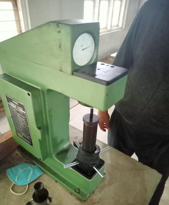
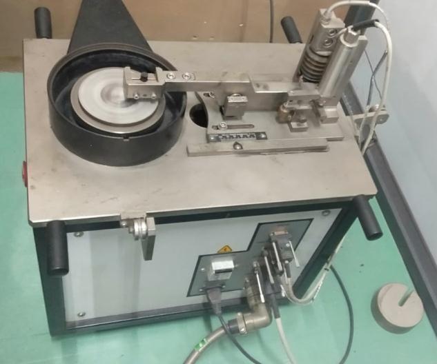
A pin on disc tester (Make: Ducom, Bangalore, India; Model: TR20 PHM 600) under dry sliding (ambient temperature)contact condition were used for the test set up. Fig. 3.2 shows test setup for wear test.
International Research Journal of Engineering and Technology (IRJET)
Volume: 09 Issue: 07 | July 2022 www.irjet.net
Forload range from0 to 60N with3 loads 5,15,25N and discspeedfrom0to1000rpmwereemployed Testpinis pressed against the surface with corresponding loads The friction disk got a diameter of 165 mm and a depth of 8 mm, EN 31 hardened steel with a hardness of 50 62 HRC and surface roughness value (Ra) 0.55 0.65 micrometer. Thecompositepingotadimensionsof8mmdiameterand 30mmlength(ASTMG99standards).
Theexperimentalresultsofcompositetestingbyvaryingthe fillercontentandloadarepresentedintable3.2andtable 3.3
Concentration WEAR 5N WEAR 15N WEAR 25N Pure 92.38403 234.245 1059.928 0.25 88.31621 53.95362 957.4183
0.5 25.64642 18.90858 321.7141 0.75 69.80835 63.97254 724.9341 1 60.79464 110.4529 825.3104
Average 67.3899 96.3065 777.861
Table3.2WearateforvariousconcentrationsofrGnP
Concentration
e ISSN: 2395 0056 p-ISSN: 2395-0072
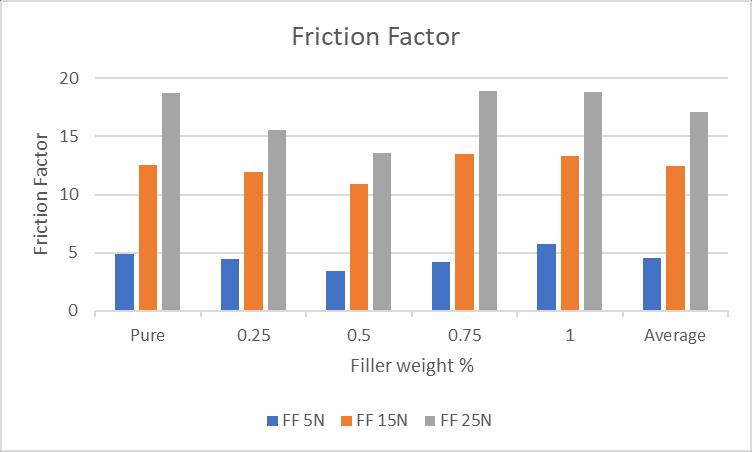
FF 5N FF 15N FF 25N
Pure 4.93032 12.54328 18.75183
0.25 4.454828 11.91577 15.53899 0.5 3.45966 10.87353 13.55351 0.75 4.16129 13.50613 18.93977 1 5.74193 13.28799 18.80157 Average 4.54961 12.4253 17.1171
Table3.3FrictionfactorforvariousconcentrationofrGnP
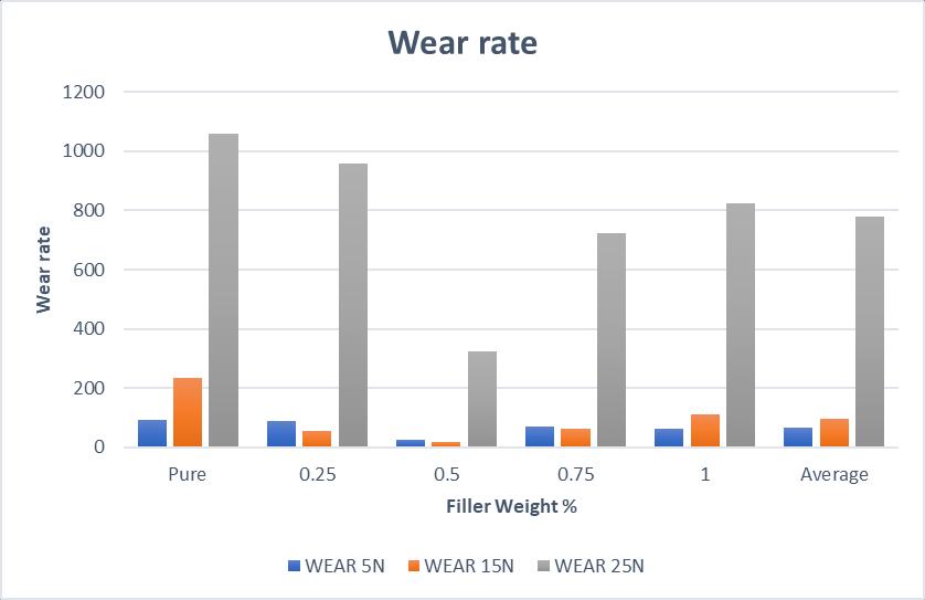
Graph3.2WearrateforvariousconcentrationofrGnP
Graph3.2FrictionfactorforvariousconcentrationofrGnP
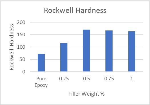
The surface hardness of the neat epoxy and epoxy based Reducednanocompositespecimensweremeasuredthrough theRockwellmicrohardness(Hv)testsetuptoreducedGnP fillers on the epoxy matrix. Graph 3.1 shows the effect of variousfillercontentsonthehardnessvalueofepoxy based nanocomposites. It is evidenced, the hardness value of specimens was enhanced with the increasing of filler content.
Neatepoxyshoweda Rockwell hardnessvalueof73HRC, and this value increased to 116 HRC (59 % rise) with the additionof0.25wt.%rGnPand171HRC(134%rise)with theadditionof0.5wt.%GnPs.Fortheotherconcentrations (0.75 and 1wt.%), rGnP embedded composites showed significant increase of the hardness i.e., 128% and 124%, respectively.Majorreasonsfortheincreaseinthehardness of particles filled composites is the fine dispersion of the particlesinthematrixgivingmoresurfaceareafortheGnPs
2022, IRJET | Impact Factor value: 7.529 | ISO 9001:2008 CertifiedJournal
International Research Journal of Engineering and Technology (IRJET)
Volume: 09 Issue: 07 | July 2022 www.irjet.net
and thereby strengthening the bond between epoxy and rGnPmatrix.
From this result, it is also evident that the highest micro hardnessvaluewasachievedbythe0.5wt%specimenwith anincrementupto171i.e134%higherthanthatoftheneat specimen(73HRC).Theincreaseinthepercentageoffiller loadingreducedgraphenenanoplatelets(varyingfrom0.1, 0.25, 0.5 and 1 wt.%) has decreased for other filler concentration. Here, infiltration between epoxy and rGnP particleishigherfor0.5%rGnPcorrespondstothehigher hardness thereby reducing nano void formation which is themaincausefortheimprovedhardnessproperties.The decreaseinhardnessathigherweightloadingof0.75wt% and1wt.%GnPisduetotheGnPagglomeration
TheaverageCoFasafunctionofslidingdistance(2000m)at the 3 different applied load values (5,15,25 N) is shown in Figure. The average coefficient of friction value of the epoxy resin matrix was decreased with the addition of fillerparticlesgraphenenanoplatelets.Thus,byincreasing the filler in matrix, the average coefficient of friction decreased.
Neat epoxy showed an average wear rate of 461.1856 mg/m, and this value decreased to 366.5627mg/m (26 % less)withtheadditionof0.25wt.%rGnPand122.089mg/m (74%less)withtheadditionof0.5wt.%GnPs.Fortheother concentrations (0.75 and 1wt.%), rGnP embedded compositesshowedsignificantdecreaseofthewearratei.e., 38%and28%,respectively.
Due to the lubricating property of the GnP, the sliding contact surface creates a lubricant film thereby an improvement in the CoF and wear rate. But for higher concentration CoF and wear rate values due to the higher filler concentration and improper interfacial bonding between the filler and epoxy led to early wear debris which generates higher CoF in weartest.Thisforeignbody wear debris sticks to the contact surface and creates a higher coefficient of friction and wear rate for the higher fillercomposites.
In this work, the effect of rGnP for wear and hardness behavior of epoxy matrix nano composites was investigated.TheconcentrationofrGnPvariedbetween 0 to 1 wt. %, with 0.25 wt.% interval and compared with results of pure epoxy composite. The following conclusionsweredrawn:Incomparisontothebaseepoxy sample, the maximum gain of 134% in the Rockwell hardnesswasachievedfor0.5wt.%rGnPloadingintothe epoxy matrix due to the superior bonding between rGnP, and epoxy. The least wear rate of 73 % was observed for
e ISSN: 2395 0056 p-ISSN: 2395-0072
0.5 wt. % rGnP loading into epoxy matrix with moderate surfacetextureproperty.
Hence,withthissuperiormechanical propertyat0.5 wt.% rGnP embedded epoxy based composites, the currently rGnP composite material finds applications where the resistancetowearisdominantandweighttostrengthratio isamajorconstraintlikeaerospaceapplications.
[1]Zhang,R.,Dowden,A.,Deng,H.,Baxendale,M.,andPeijs, T.(2009), “Conductive network formationinthemeltof carbon nanotube/thermoplastic polyurethane composite”, Composites Science and Technology, 69, pp 1499 1504.
[2]SeenaaI.Hussein. Nano Hybrids and Composites (2018). ISSN: 2297 3400, Vol. 22 pp 23 33. doi:10.4028/www.scientific.net/NHC.22.23
[3]DineshKumar Composites PartA:AppliedScience and Manufacturing Volume84,2016,Pages364 376.
[4]NICBerhanuddin.2017J.Phys.:Conf.Ser.914 012036.2017.Journal ofPhysicsConferenceSeries 914(1):012036.DOI:10.1088/1742 6596/914/1/012036
[5]A Purohit, A Satapathy. A study on processing, characterization and erosion behavior of fish (Labeorohita)scalefilledepoxymatrixcomposites.2009. MaterialsDesign,Volume7. doi.org /10.1016 /j.matdes.2008.10.033
[6]Chen,W.X.,Li,F.,Han,G.,Xia,J.B.,Wang,L.Y.,Tu,J.P.,and Xu, Z.D. (2003), “Tribological of carbon nanotube filled PTFEcomposite”,TribologyLetter,15,275 278.
[7]Jacobs, O., Xu, W., Scha, B., and Wu, W. (2006), “Wear behaviour of carbon nanotube reinforced epoxy resin composites”,TribologyLetter,23,pp65 75.
[8]Zoo, Y.S, An, J.W., Lim, D.P., and Lim, D.S. (2004), “Effect of carbon nanotube addition on tribological behaviour of UHMWPE”TribologyLetter,16,pp305 309.
[9]Huaiyuan,W.,Li,C.,Xiaoshuang,Y.,Lixiang,Y.,Lin,Y., Yanji,Z,Andrew,T.H.,Andrew,I.M.,Patrick,T.,and Klaus, F. (2014), “Anisotropy in tribological performances of long aligned carbon nanotubes/polymer composites”, Carbon,67,pp38 47.
[10] Dong, B., Yang, Z., Huang, Y. and Li, H.L. (2005), ‘Studyontribologicalpropertiesofmulti walledcarbon nanotubes/epoxy resin nanocomposites’, Tribology Letters,20(3 4),251 254.