International Research Journal of Engineering and Technology (IRJET) e ISSN: 2395 0056

Volume: 09 Issue: 07 | July 2022 www.irjet.net p ISSN: 2395 0072
International Research Journal of Engineering and Technology (IRJET) e ISSN: 2395 0056
Volume: 09 Issue: 07 | July 2022 www.irjet.net p ISSN: 2395 0072
1Post Graduate student in structural engineering ,department of civil engineering , CBS Group of Institutions, Fatehpuri, Jhajjar , Haryana, India
2Assistant Professor, department of civil engineering , CBS Group of Institutions,Fatehpuri, Jhajjar , Haryana, India ***
Abstract In recent times steel structures are being adopted for construction of structures conforming to their advantages over conventional RCC structures. India is the world's second largest cement producer, so before the year 2000 most of the constructions were done in RCC and there were other numerous reasons for this some of them being, in RCC construction lesser skilled labours were required, the deadline of the project did not matter ,there was a lack of higher grade steel and large steel sections were not readily available but after the year 2000 steelstructuresweregaining popularity and their execution was started ,the chief reason for this was the shift in market from cost oriented to time oriented construction. During this time there was unavailability of higher section sizes in steel tubes so built up composite structures were preferred.Theproductionofhigher cross section tube sizes was started in 2019 by some vendors like TATA ,APL Apollo, this has revolutionizedtheconstruction market and a some of new constructions are being done in steel structures now.
Key Words: Steel structure, Earthquake, Seismic, Metal decksheet,I Section,Compositetube.
A steel structure may be defined as a metal construction made mostly of structural steel components and sections thatarejoinedtooneanotherinvariouswayslikewelding, bolting, or riveting to carry loads from the structure (also known as dead loads) andfrompeopleinsidethestructure (also known as Live Loads) &providesrigidity.Duetosteels highstrengthtocountertensileandcompressivestresses, thesestructuresarereliableandrequirelessrawmaterialin comparisontosomeothertypesofstructuralmaterialssuch asconcrete.
To meet the requirements of a project, structural steel is manufactured with a certain shape and chemical composition. In present day construction practices, structuresmadeofsteelareemployedalmostforeveryother typeofstructurewhichincludeshigh risebuildings,towers, bridges,infrastructure,supportsystemsforequipmentand machinery,heavyindustrialbuilding,heavyindustrialplant, etc.
Adheringtoeverystructural specification,thedimensions forsteelmembersformedbyhotandcoldrolledprocedures are connected by welding or bolting flat and bent plates together.FrequentlyadoptedshapesaretheIshapedbeams, Hollowsections,angle,channel,andplates.
Structuresmadefromsteelsectionsarequicklybuiltatthe projectsitebecausemajorityofbuildingcomponentscould be prefabricated at the workshop or Steel manufacturing facility. The Expansion of any steel Structure can comparativelybeveryeasyandfast.Assteelcanbemolded into different shapes as a result repair & rehabilitation and/or retrofitting is conveniently possible. As the steel building components are prepared in the workshop, the erectionofthestructureatsiteisfastincomparisontoother buildingmaterials.
Because of their flexibility, they are excellent at resisting dynamic (changing) forces like wind or seismic forces. In earthquake zones, the fact that steel may bend without crackingservesasawarning.Thereisalargeselectionofpre madestructuralsections,includingI,C,andanglesections. Theycanbefashionedintoanyshapeandcoveredwithany kindofshape.Bolting,welding,andrivetingarejustafewof the connecting techniques that are accessible. we can also recycle steel. About one third of the energy required to producenewsteelfromscrapsteelisusedinthisprocess.
Before forming a structural system, analytical approaches and assumptions must be fairly clear and final. The time consumedtodesigna connectionislongerthanthatofan RCC structure connection. The cost of structural steel (especially India) is higher than RCC. Skilled workforce is required.Steelhasapropertyofbecomingsoftandmelting whenexposedtoveryhightemperatures.
Additional fire protection, such as spray on fireproofing, structuralsteelbuildingscanwithstandhightemperatures, which in turn enhances security. They tend to corrode in damp or marine environments. Hence, consistent care is needed.
International Research Journal of Engineering and Technology (IRJET) e ISSN: 2395 0056
Volume: 09 Issue: 07 | July 2022 www.irjet.net p ISSN: 2395 0072
Allstructuraldesignandanalysismustadheretothelatest Provisionsof theIndianStandardcodesforSteelandRCC constructionprimarilyIS800:2007andIS456:2000.
Specialqualityweldjointsallowing100%tensionstrength shallberequired.Non destructivetestingtechniquesshould be used for weld quality inspection and control. For slip criticaljointsaslipfactorof0.5shallbeusedinaccordance with IS 4000 with specified surface treatment and preparation.
TheunitweightofmaterialsshallconformtoIS875 Part1. Theself weightofstructureisautomaticallycalculatedbythe analysissoftwaredependinguponthecross sectionalarea anddensityofeachmember.
DensityofR.C.Cmembers=25.0kN/m3
DensityofP.C.Cmembers=24.0kN/m3
Densityofstructuralsteel=78.5kN/m3
Densityofbrickmasonrywalls(230/115mmthick)=20.0 kN/m3
Drydensityofsoil =18.0kN/m3
Densityofsaturatedsoil=20.0kN/m3
Densityofwater=10.0kN/m3
Densityoffloorfinish =24.0kN/m3
Densityofplaster=24kN/m3
ScreedandFinishes(50mm)ontypicalfloors=0.05m×25= 1.2kN/m2
ServiceLoads=1kN/m2
PartitionWalls=1kN/m2
ScreedandFinishes(150mm)=0.150m×25=3kN/m2
ServiceLoads=1kN/m2
ParapetWalls(1.5meters)=0.45kN/m
Liveloadonallfloors=3kN/m2
LiveloadonTerrace=1.5kN/m2
BasicWindspeed=50m/s
Seismiczone=IV
Soiltype=II
Responsereductionfactor=5
The sheeting is designed for Self weight of the Slab and Sheeting,andErectionloads
ClearthicknessofConcreteslab =80.00mm Doverallthick =155mm
Avgthk.ofConcreteslabwithindecksheeting =37.50mm averagethick =118mm
Serviceload =1kN/m2
Partitionload =1kN/m2
Liveload =3kN/m2
Service+partition+liveload =5.000kN/m2
Flooringthickness =50.00mm
Flooringdensity =24.00kN/m3
ErectionLoad =5.00kN/m2
Sheetingthickness =1.00mm
Self Weightofthesheeting =11.96kg/m2
Dead weight of deck slab =(0.08+0.0375) x 252+ 0.050 x 24+0.1196 = 4.3kN/m2
Zofsheeting =36.26cm3
Spacingofbeam(Maximum) =2.00 m
Loadtobecarriedbysheeting =9.3 kN/m2 (80+35)*.025+5(Erection)+50x0.024+.1196(selfweight)
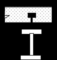
DepthoftheDeckingProfile =75.00mm
Flangewidthofsupportingbeamassumed =140.00mm EffectiveSpanfortheDeckingSheetDesign =1.94m 230 75 Fig 1:DeckSheetProfile
B.M FACTORFORSHEETING =8.00
AllowablebendingstressinSheeting =165N/mm2 (0.66*250MPaconsidered)
BendingMoment(9.3x2x2x1000/8) =4.65kN m BendingStress(4650000/(36.26x1000))=129.81N/mm2 <165 O.k
TotalLoad =9.3kN/m/m SPAN =2.00m SPAN(Effective) =1.94m
IXX =1473000mm4 Defl.Coeff. =5/384
LimitingDeflectionRatioforDeckSheet =200
2022, IRJET | Impact Factor value: 7.529 | ISO 9001:2008 Certified
International Research Journal of Engineering and Technology (IRJET) e ISSN: 2395 0056
Volume: 09 Issue: 07 | July 2022 www.irjet.net p ISSN: 2395 0072
AllowableDeflection =9.68mm
VerticalDeflection =5.76mm (5x9.3x(1.935x1000)^4)/(384x200000x1473000) <<9.68 O.K
SPANOFTHEBEAM =7.50m
Provide Beamas =ISMB350 Widthofthefalange =140.00mm
Areaofthesection =6671.00mm2
Ixxofthesection =136303000mm4
Zxxofthesection =778874mm3
Rminofthesection =28.40mm
Depthofthesection =350.00mm Flangethickness =14mm Webthickness =8mm Flangewidth =140mm
Design of beam by using Composite action
1) Dead load of Concrete slab & self weight of beam and constructionloadof1.5kn/sqmistakenbySteelbeamonly.
2) Only balance live load & flooring load is resisted by compositeconstructionaftertheconcreteishardened.
3)Areaoftheconcretewithinprofiledepthisignoredfor effectivewidthcalculationofslab.
4)DesignofshearconnectorasperIS:11384 1985for ultimateshearcapacityofconcrete.
ModulurRatio =280/3scbc, =280/3x8.5=10.98
DepthofDeckSheeting =70.00mm
Area of reinforcement perpendicular to Beam=2.50 cm2 (Astprovidedinslab)
EffectiveWidthofSlabLesserofthefollowing
1)Span/4=7.5x1000/4 =1875.00mm
2)12xslabthk.+Flangewidth =12x80+140 =1100.00mm
3)Spacingofbeams =2000.00mm
Soeffectivewidth =1100.00mm
Transformedwidth =1100/10.98 =100.18mm
C.Gfrombottom = (6671x350x0.5+100.2x80x[350+75+80x0.5])/(6671+100.2x 80) =333.27mm
Ixxofcombinedsection 136303000 + 6671x(333.3 175)^2 + 100.2x80^3/12 + 100.2x80x(350+75+80x0.5 333.3)^2 =4.47E+08mm4
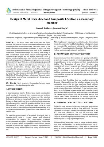
Zxxatbottom=446757145.4/333.3 =1.34E+06mm3 100.2 80 75 14 350 333.27 140
Fig 2: Isectionwithdeckslabinequivalentsteelarea
Stresses due to Dead weight + Construction live load (only Steel beam action)
UdlonbeamWITHconstructionloadof1.5kn/sqm =0.80t/m {(80+35)x0.001x2.5+0.01196}x2+0.006671x7.85+0.15
BendingMoment0.801x7.5x7.5/8 =5.63t m Bendingstress =56340516.8/778874 =72.34N/mm2
Deflectioninbeam =12.11mm (5x0.80x10x(7500)^4)/(384x200000x136303000)
Stresses due to Imposed Load (composite action)
AdditionalEquivalentUDLduetoBrickWall=0.00kN/m Additionalliveloadis5 1.5 =3.5kn/sqm
Udlonbeam=(5 1.5+0.05x24)x2 =9.40 kN/m BendingMoment=9.4x7.5x7.5/8 =66.09kN m BendingStressatbottomofsteel =66.09375x 10000000/1340542.46 =49.30N/mm2
Total BendingStresses=72.34+49.30 =121.64N/mm < 165 O.K
Deflectionduetobalance Liveloadandfinishing 5x9.4x(7500)^4/(384*200000x446757145.4) =4.33mm DeflectionFactorforDead Load =1000.00
Allowabledeflection=7500/1000 =7.50mm (AsPerIS14687 1999cl:7.5(b))
Total'deflection' =4.3+12.11 =16.44mm < 23.1 O.K
Allowabledeflection =7500/325 =23.08mm Zxxattop=446757145/(350+75+80 333.3) =2.60E+06mm3
Bendingcompressivestressinconcrete 66.1x1000000/(2601447.5x10.98) =2.31 N/mm2
2022, IRJET | Impact Factor value: 7.529 | ISO 9001:2008 Certified Journal
International Research Journal of Engineering and Technology (IRJET) e ISSN: 2395 0056
< 8.33 O.K
Allowablebendingcomp.Stressinconcrete =8.33 N/mm2
ForM25Grade =25/3 (Cl.13.0IS:11384 1985)
Shearcapacityofstud =30.79kN
Thicknessofslab =250.00mm Floorthickness =50.00mm TotalLoad 1.0DL+0.5LL+EQL =11.19 kN/m2 Lengthofbeam =7.50m Spanofbeam =2.00m TotalLoad =167.92kN Z =0.24 I =1.50 Sa/g =2.50 R =5.00
Ultimate
ShearStudSpacing:
Maximum Horizontal Shear (fcc) (Page No:7 IS:11384 1985)0.36*fckbXu= 0.36x25x1100x80/1000=792.00kN
Shearcapacityofeachstud =31.42kN Diaofstud =20mm Heightofthestud =100mm No.ofstudsatcrosssection =2 No.ofstuds=792/(2x31.4159265358979) =12.61
SpacingofstudsReqired:3750/12.6 =297.50mm Spacingofstudsprovided =250.00mm <600mm <4x80mm
ShearperMeterlength(Q)=792/3.75 =211.20KN/M Shearresistanceofslabisminimumofthefollowing(Page No:10IS:11384 1985)
0.232x2x80xSQRT(25)+0.1x2.5x500*2=435.60kN/m 0.623x2x80xSQRT(25) =498.40kN/m 211.200<435.6O.K
( CL.10.IS:11384 1985)
Lengthoftheshearconnector =100mm > 50mm O.K.
Projectionofshearconnectorintotheslab =1000,100mm > 25mm O.K.
Min.DiameterofHead =1.5xdia =30mm
Diaofstud =20.00mm Yieldstressofstud =245.00N/mm2
Maximumpermissibleshearstress =98.00N/mm2 Areaofstud =314.16mm2
Seismiccoefficient,Ah =0.09 Horizontalforce =22.67kN Spacingofstud =250.00mm Noofstudsprovided =30.00 Say30
Shearcapacityofstud =924 kN > 22.67kN OK
Structuresmadefromsteelsectionsarequicklybuiltatthe projectsitebecausemajorityofbuildingcomponentscould be prefabricated at the workshop or Steel manufacturing facility.
TheExpansionofanysteelStructurecancomparativelybe veryeasyandfast.
SteelstructureshavegoodscrapvaluewithrespecttoRCC. In tubular structures, members are capable to resist both directionoflateralforcesduetothegoodinertiapropertyin bothdirections.
Composite tubes constructions in columns is easy with respecttoIsectionencasedinconcretecolumn.
In the composite tube construction, no shuttering, de shuttering,andbarbendingisrequired.
Dynamicforcesthatchangewithtimesuchaswindand/or seismicwavesaresmoothlyresistedbytheflexilenatureof thesteel.
Onlyonethirdenergyisrequiredtocreatenewsteelfrom scrappedmaterialthanfreshsteelalloyachievedfromiron ore.
[1] Duggal, S.K Limit state design of steel structures. 3 Ghobaraha.etal.,“pushoveranalysisofsteelframes”, (1997)
[2] NSubramaniandesignofsteelstructuresbyLimitstate method.
Volume: 09 Issue: 07 | July 2022 www.irjet.net p ISSN: 2395 0072 © 2022, IRJET | Impact Factor value: 7.529 | ISO 9001:2008 Certified Journal |
International Research Journal of Engineering and Technology (IRJET) e ISSN: 2395 0056
[3] IS1893(Part1):2002,(2002),“IndianStandardcriteria for earthquake resistant design of structures”, (5th revision).
[4] IS 800: 2007, “Indian Standard criteria for design of steelstructure.
[5] Hassan, O.F., Goel, S.C.(1991).”Modelling of bracing membersandseismicbehaviorofconcentricallybraced steelframes”.
[6] K.G.Vishwanath, “Seismic response of Steel braced reinforced concrete frames”, International journal of civilandstructuralengineering(2010)
[7] Khatib, I.andMahin, S., Dynamicinelasticbehavior of chevronbracedsteelframes,FifthCanadianConference onEarthquakeEngineering,Balkema,Rotterdam,1987, pages211 220
[8] K.K.Sangle,K.M.Bajori,V.Mhalungkar,“SeismicAnalysisOf HighRiseSteelFrameWithAndWithOutBracing”,2012 9 Mateescu, G., & Molodovan, A. Resarch on seismic behaviorofsteelstructures.
Volume: 09 Issue: 07 | July 2022 www.irjet.net p ISSN: 2395 0072 © 2022, IRJET | Impact Factor value: 7.529 | ISO 9001:2008 Certified Journal |