Volume: 09 Issue: 07 | July 2022 www.irjet.net p-ISSN: 2395-0072
Design and Control of Half-Bridge Resonant Converter Topology of PID Controller
1PG Student, Department of EEE, Dr.AIT, Bengaluru, Karnataka, India
2Assistant Professor, Department of EEE, Dr.AIT, Bengaluru, Karnataka, India ***

ABSTRACT- The closed loop LLC resonant DC DC half bridge converter are used in low medium and high power applications for an high efficiency. This paper presents the closed loop PID converter for an LLC DC DC half bridge converter with both linear and non linear loads. These converter are used in high power density for a battery charging and conventional energy systems. These converter are used for more high power switching frequency for reducing the loss of switching devices and conduction losses. Power factor is improved by soft switching technique by a closed loop PID controller. The measured maximum efficiency is 95% and the hardware and simulation result of the resonant LLC DCDC half bridge is presented.
INTRODUCTION
In the closed loop resonant LLC DC DC half bridge converter are commonly used in now a days where 10%ofelectricvehicleschargingstationshasinstalled India. Where by estimating of the electric vehicles is increasing up to 50% of previous year by increasing the electrical vehicles there is no fuel gases are presented whereas the pollution will not occur the greenhouse will be presented by the economical and concerns of environmental. Hencenowadays both fuel gas and the electric energy is used for the vehicles where it is known as hybrid vehicles. The charging batteries are used for the electrical motors and vehicles. Where the batteries will provides the constant current and constant voltage of battery pack charge. The efficiency, power density, switching frequency, switching losses, conduction losses, and constant voltage should be gained from the DC DC resonant half bridge converter. The ZVS and ZCS is usedfortheMOSFETonandofflosses.Intheresonant tank is used for the half bridge AC DC converter. The resonant tank includes the resonant inductor, resonant capacitor and magnetizing inductor. For a constantoutputvoltagetheclosedloopPIDcontroller is used which reduces thepowerlosses andimproves the power quality. The converters are connected to
linearloadsandnon linearloadslikebatteries,motor.The linearloads voltageisdirectlyproportional to current.The non linear loads voltage is inversely proportional to current that are rectifiers, variable speed drives and electronic devices. There are three types of resonant converters that is series resonant converters, parallel resonant converters, series parallel resonant converters. The zero voltage switching and zero current switching techniqueisusedforasoftswitchingmethodtoreducethe switching losses and conduction losses. Hence the loss decreases the power quality and the efficiency increases. The harmonics are also reduced due to soft switching method by a resonant LLC circuit and LC filters where the LCfiltersisknownaslowpassfiltersthatwhichattenuates thelowpassbandwidthsignal.Themainaimofthisproject istoobtaintheconstantoutputvoltagewithhighefficiency, high power quality and low conduction losses and low switching losses. The calculation is done detailed with the designprocedureindetailoftransformer windingscurrent of primary side and secondary side. The theoretical value andpracticalvalueobtainedsame.Theexperimentalresult isobtainedandpresented.
HALF BRIDGE RESONANT CONVERTER
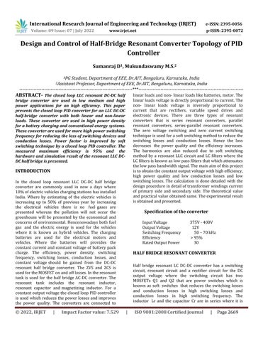
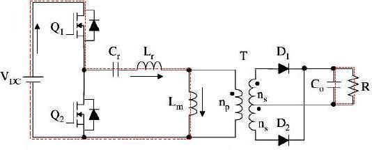
Half bridge resonant LC DC DC converter has a switching circuit, resonant circuit and a rectifier circuit for the DC output voltage where the switching circuit has two MOSFETs Q1 and Q2 that are power switches which is known as soft switches that reduces the switching losses and conduction losses in high switching losses and conduction losses in high switching frequency. The inductor Lr and the capacitor Cr are in series where it is
International Research Journal of Engineering and Technology (IRJET) e ISSN: 2395 0056 © 2022, IRJET | Impact Factor value: 7.529 | ISO 9001:2008 Certified Journal | Page2669
the converter InputVoltage 375V 400V OutputVoltage 12V SwitchingFrequency 50 70kHz Efficiency >95% RatedOutputPower 30
Specification of
Sumanraj D1 , Mukundaswamy M.S.2
International Research Journal of Engineering and Technology (IRJET) e ISSN: 2395 0056
Volume: 09 Issue: 07 | July 2022 www.irjet.net p-ISSN: 2395-0072
formed by a resonant tank circuit. The resonant conductor inductor Lm is connected parallel across the primary side of transformer. The tank consists of Lr, Lm and Cr which are in series with a load. The resonant circuit and the load as voltage divider method.
mode of the operation will ends and the output value becomeszero.
Fig.No1.Half bridge resonant converter
HALF BRIDGE RESONANT CONVERTER OPERATION
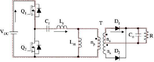
MODE1
When the supply voltage is given to the half bridge resonant LLC DC DC converter, the MOSFET switch Q1 s turned on while the switch 2 is turned off. When the switch Q1 s turned on the resonant inductor LR current reversesandit is flowingthroughthediodewhichisanti parallel to MOSFET switch. The zero voltage switch conditionisusedfortheswitchQ1thegatesignalofpulse widthmodulationisapplied.WhentheswitchQ1sturned on the transformer of the secondary side of the diode D1 acts as a forward bias. The magnetizing conductorLm is chargedwiththeconstantvoltage.
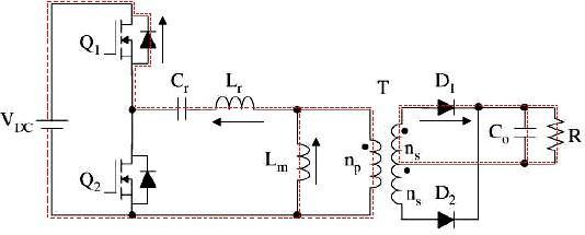
Fig.No3.Mode2 operation of resonant converter
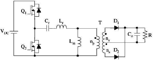
MODE3
When the both resonant conductor and magnetizing inductoraresameasoutputcurrentisnull Thesecondary sides of the rectifier both diode D1 andD2 are reverse biased.Thesystemvoltageisverylessthantheoutput voltage andMOSFETQ1sturnedoff.
Fig.No2.Mode1 operation of resonant converter
MODE2
When MOSFETs switch Q1 is on in mode1 operation the current is lowing trough the switch Q1. This mode will be turnedonwhentheresonantinductorLr,currentbecomes positive. The magnetizing inductor Lm is charged by an outputvoltagewhenitisinforwardbiascircuit.Whenthe resonant inductor and magnetizinginductor aresamethis
Fig.No4.Mode3operationofresonantconverter
HALF BRIDGE RESONANT DC-DC CONVERTER
OPEN LOOP
Resonant converter has a two switches and the resonant tank with two capacitors. The capacitors divides the voltage level with the input supply voltage where the MOSFET switches is turned on by an gate signals with an differentpulsesignalsduetotheopenloopwhereprimary voltage is varied then secondary voltage should be constant voltage where it can be step input variation waveform is shown in the simulation waveform
©
|
Certified
| Page
2022, IRJET
Impact Factor value: 7.529 | ISO 9001:2008
Journal
2670
International Research Journal of Engineering and Technology (IRJET) e ISSN: 2395 0056
Volume: 09 Issue: 07 | July 2022 www.irjet.net p-ISSN: 2395-0072
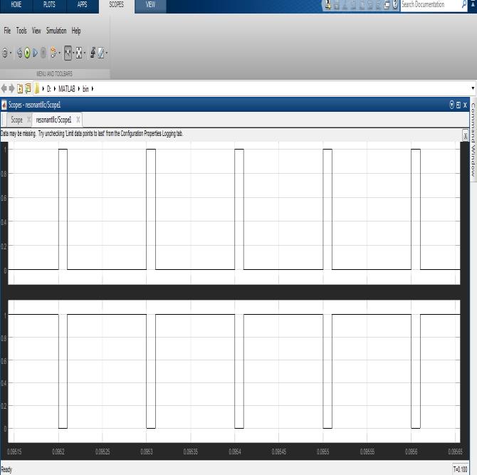
Fig.No5.Open loop converter
Fig.No6.Driving pulse of Mosfet switching
MOSFET OPERATIONS
Inthishalf bridgeDC DCresonantconvertertherearetwo MOSFET’sarepresentedwheremosfetswitchQ1isturned on then mosfet Q2 will be off and vice versa. Due to present on soft switching method the ZVS and ZCS is providetheswitchinglossesandconductionlosseswillbe decreased whereas when the Q1 is turned on it is in the rise time and starts conducting up to current flow of resonant inductor when the current reverses the diode voltage of magnetizing inductor the switch is in the fall time and the switch Q1 will be off then the Q2 will be on then it will starts conducting up to an delay time that Q2 willbeturnedoffthanviceversa.
Fig.No7.Output waveform CLOSED LOOP
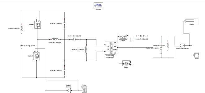
Inthisclosedloopcircuittheworkingissameas theopen loopcyclebutthegatesignalofMOSFETsswitchesisgiven by the proportional integral derivative controller is given tothegatesignalbyanNOTgateduetotheswitchingtime where NOT gates used to switch ON and OFF only one switch where two switch cannot turn ON at a time. By using proportional integral derivative controller the switchinglossesandtheconductionlossesarereducedby an soft switching method. When the primary voltage is varied the secondary voltage is constant by an good efficiency,power quality andgoodswitchingfrequencyby anconstantoutputvoltage.
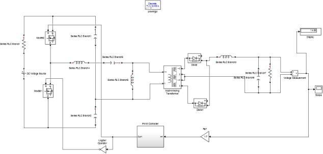
Fig.No8.Closed loop converter
© 2022, IRJET | Impact Factor value: 7.529 | ISO 9001:2008 Certified Journal | Page2671
International Research Journal of Engineering and Technology (IRJET) e ISSN: 2395 0056
Volume: 09 Issue: 07 | July 2022 www.irjet.net p-ISSN: 2395-0072
SIMULATION
Fig.No9.PID Controller
PID Controller
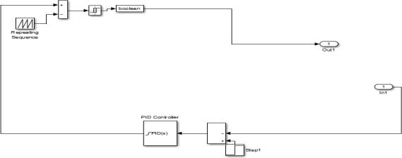
PIDcontrollerisasensorsignalwhichisusedforfeedback control unit where it senses the signal and compare the outputofthecircuitandgivesacertainoutputvoltage.The PID denotes the proportional integral and derivative. Where the P is used for the improving the transient response rise time and settling time, I and D used for the integralandderivativeofthecomponent.
Fig.No11.Driving pulse of Mosfet switching
The resonant LLC DC DC halfbridge converter is simulated in both open loop and closed loop cycle in a MATLAB/ Simulink where a constant output voltage waveform is obtained. The primary input voltage of MOSFETs and the capacitor voltage is shown in the waveforms. The primary current of the transformer is seen by an scope. All the waveforms like diodes, capacitors, MOSFET switches an input voltage, output voltage and the gate signals are shown in MATLAB/ Simulinkwaveforms.
Hardware Results
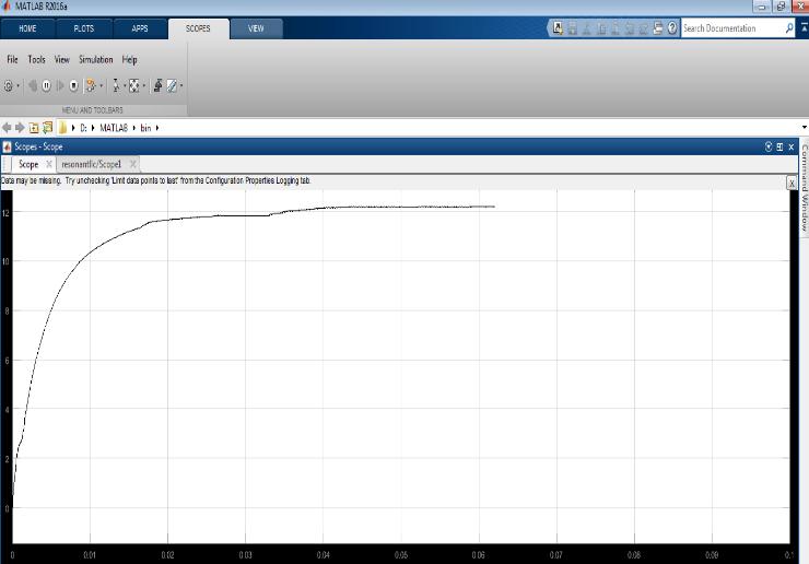
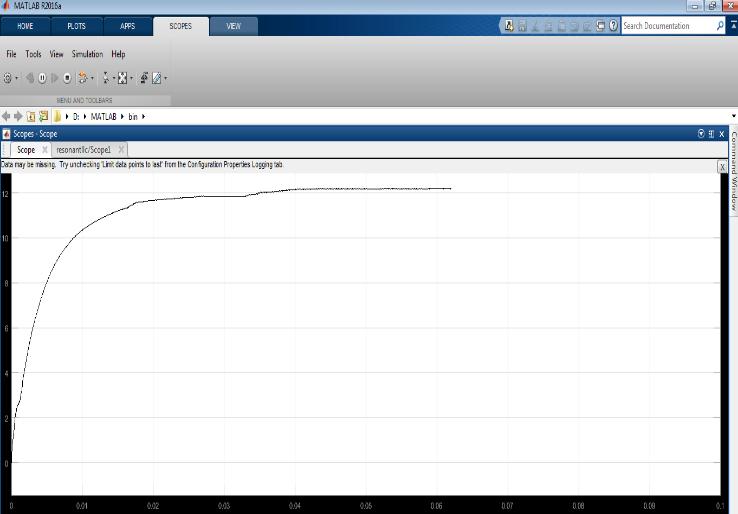
Fig.No10.Output waveform
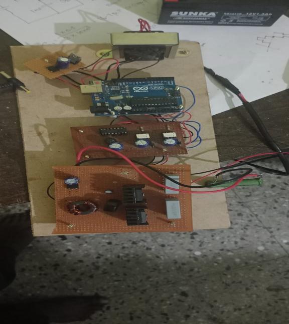
Fig.No12. Hardware of LLC resonant converter
© 2022, IRJET | Impact Factor value: 7.529 | ISO 9001:2008 Certified Journal | Page2672
International Research Journal of Engineering and Technology (IRJET) e ISSN: 2395 0056
Volume: 09 Issue: 07 | July 2022 www.irjet.net p-ISSN: 2395-0072
In this, the battery supply is provided to the primary of the LLC converter which varies in the range of 12V to 18V. Thesecondaryisrectifiedusingthedioderectifierand providedto load. A voltage sensor is used to measure the load voltage and provide it as feed back to the controller. Basedon thefeedback signal the pulses will be varied and load voltage isregulated. The load voltage is maintained as 12V irrespectiveoftheinputchanges.
CONCLUSION
The series resonant LLC half-bridge DC-DC converter does not provide a constant output voltage. To obtain theconstantsecondaryvoltagethe
resonanttankcircuit, the LC filters and proportional integral derivative controllers areusedtogetaconstant outputvoltageby aswitchingfrequency,powerqualityandefficiency.The zero voltage switching and soft switching methods are obtained toreducetheconductionlossesand switching losses. The proportional integral derivative controller are used to provide constant output voltage. This resonant converter is simulated in MATLAB/ Simulink andwaveformsareobtained.
REFERENCES
[1] Robert L. Steigerwald, “A Comparison of Half-bridge resonant converter topologies,” “IEEE Transactions on PowerElectronics”,Vol.3,No.2,April1988.
[2]A.F.WitulskiandR.W.Erickson,“Designoftheseries resonant converter for minimum stress,” “IEEE Transactions on Aerosp. Electron”. Syst, Vol. AES-22, pp. 356-363,July1986.
[3] J.P.Lee,B.D.Min,T.J.Kim,D.W.Yoo,andB.K. Lee, “A novel topology for photovoltaic series connected dc/dc converter with high efficiency under wide load range,” in IEEE 2007 Power Electronics Specialist Conference,2007,pp.152-155.
[4] Y. T.Jang,M.M.Jovanovic,andD.L.Dillman,“Light load efficiency optimization method,” in “IEEE 2009 Applied Power Electronics Conference and Exposition”, 2009,pp.1138-1144.
© 2022, IRJET | Impact Factor value: 7.529 | ISO 9001:2008 Certified Journal | Page2673
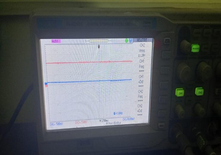
Fig.No13.Output DC Voltage
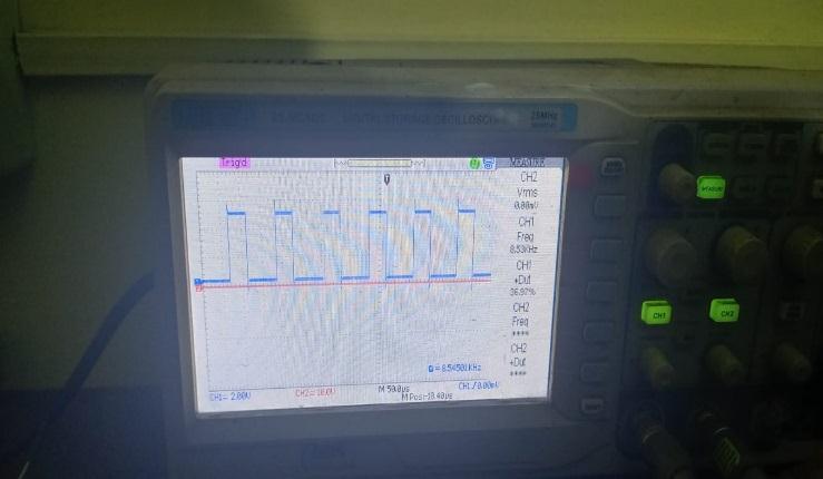
Fig.No14. Gate pulse of MOSFET switch 1
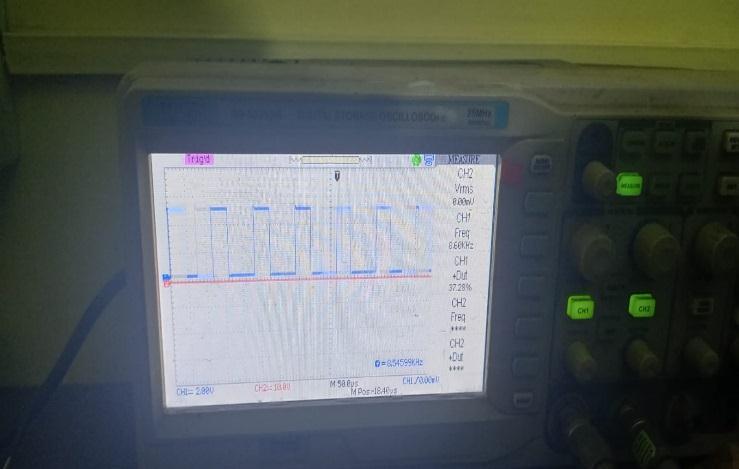
Fig.No15. Gate pulse of MOSFET switch 2
[5] W. S. Choi and S. M. Young, “Improving system reliability using FRFET in LLC resonant converters,” in “IEEE 2008 Power Electronics Specialist Conference”, 2008,pp.2346 2351.
[6] M. Z. Youssef and P. K. Jain, “A front end self sustainedLLCresonantconverter,”in“IEEE2004Power ElectronicsSpecialistConference”,2004,pp.2651 2656.
[7] M.M.A. Rahman, “Single phase single stage 3 Level AC to DC series resonant converter”, “IEEE EIT proceedings”,2004,pp,569,573.
[8]D.M.Divan,“Theresonantdclinkconverter Anew concept in static power conversion,” in “Proc. Conf. Rec. IEEEIASAnnu.Meet”,1986,pp.648 656.
International Research Journal of Engineering and Technology (IRJET) e ISSN: 2395 0056 Volume: 09 Issue: 07 | July 2022 www.irjet.net p-ISSN: 2395-0072 © 2022, IRJET | Impact Factor value: 7.529 | ISO 9001:2008 Certified Journal | Page2674