International Research Journal of Engineering and Technology (IRJET)

e-ISSN: 2395-0056
Volume: 09 Issue: 07 | July 2022 www.irjet.net p-ISSN: 2395-0072
e-ISSN: 2395-0056
Volume: 09 Issue: 07 | July 2022 www.irjet.net p-ISSN: 2395-0072
GANESH B. PATIL1, PROF. P.S. TALMALE2
1,2 K.C.Y.S’Late G.N. Sapkal COE, Nashik, M.E.(Mechanical)(Design Engineering) ***
Abstract Over the 12 months lots of paintings has been executed and remains perseveringwith with first rate attempt to lessen the fee and enhancing the overall performance of compression spring and additionally look at the evaluation of failure in spring The purpose of this challenge is to look at present layout of helical spring and productionthe springand perform the strain evaluation of helical anxiety spring for Tractor seat .To decreased stresses the time of dynamic loading circumstance, implemented on helical spring. Also capable of maintain at one of a kind load circumstance. At one of a kind load circumstance and strain we've test the failure evaluation of spring. In trendy we are able to look at fatigue lifestyles evaluation of spring via way of means of the use of experimental evaluation .additionally look at the impact of various the variety of turns of the spring in investigated for helical compression spring, the suspension of spring needs to be changed with the intention to lessen the strain and adventure must be snug i.e. jerk unfastened adventure. Due to damping the helical spring receives split and which reasons the extreme accident.so powerful layout of helical spring wished for tractor seat to get consolationand to face up to vibration.
Key Words: Helical compression spring, finite element analysis, fatigue life analysis, experimental analysis.
Most of the issue utilized in heavy automobile motors is subjected to excessive pressure loading and they're designedtoresistthestructuralinadditiontofatiguefailure evaluation. The Tractor seat failure has been out to be because of fatigue failure, so designers and engineers are involved approximately the very excessive cycle fatigue. Failure of any mechanical issue is rely on the loading condition,cloth,issuelayoutanditsproduction.Toenhance the existence of the issue the cloth used could be very excessivepowersteelsandwidespreadproductionsystem is observed which offers the fatigue failure of mechanical issueisreliesupononloadingsituations.Mostofthetractor seat are failed due fatigue pressure appearing on due to recitativeloadduevibrationofautomobile.Helicalsprings are extensively used in lots of engineering programs because of their importance. Helical compression springs areusedextensivelyallaroundtheworld.Ithasspecificsort of programs in specific vicinity Springs are utilized in mechanical system with transferring parts, to soak up hundreds,whichcanbecontinuously,orabruptvarying.The
absorption of the hundreds takes region withinside the shape of elastic energy. Coil springs are product of rods whichmightbecoiledwithinsidetheshapeofahelix.The layout parameters of a coil spring are the rod diameter, springdiameterandtherangeofcoilturnsinkeepingwith unitlength.Compressionspringscanbecylindrical,conical, tapered, concaveor convex in shape. Vehicle suspension machineisproducedfromspringswhichhavefundamental position in strength switch, automobile movement and driving.Therehasbeenloadsstudieshasbeenperformedto locate optimized answer for helical spring relying at the application.TheJineeLeehasproposedaPseudospectral techniquewhichbecomecarriedouttotheloosevibration evaluationofcylindricalhelicalsprings.Thedisplacements andtherotationsareapproximatedwiththeaidofusingthe collection expansions of Chebyshev polynomials and the governingequationbecomecollocated[1].A.M.Yu,Y.Hao has finished analytical observe at the loose vibration evaluation of cylindrical helical springs with noncircular cross sections. They have formulated express analytical expressions of the vibrating mode shapes of cylindrical helicalspringswithnoncircularcross sectionsandthequit situationsclamped clampedandclamped loose,theusage ofthesymboliccomputingpackagedealMATHEMATICA[2]. L.E.Beckeretal.linearizeddisturbanceequationsgoverning theresonantfrequenciesofahelicalspringsubjectedtoa static axial compressive load are solved numerically the usageoftheswitchmatrixtechniqueforclampedendsand roundcross segmenttosupplyfrequencylayoutcharts[3]. The scope of K.MIchalczyk paintings consists of the dedicationofthepressureamplitudeswithinsidethespring for the given parameters of elastomeric coating, on the consecutive resonance frequencies [4]. Mohamed Taktak hasproposedanumericaltechniquetoversionthedynamic conductofanisotropichelicalspring[5].Theanalyticaland numerical fashions describing wave propagation, of slow excitations in time has been investigated with the aid of usingAiminYu,etal.[6].SurajKumaretalhavepurposedair springthatistolimitionthevibrationataappropriatestage as in keeping with requirements. Anis Hamza et al has studied the vibrations of a coil, excited axially, in helical compressionspringswhichincludestampingrammersare discussed. He has evolved a mathematical components whichbecomemadefromamachineof4partialdifferential equations of first order hyperbolic type, because the unknownvariablesareangularandaxialdeformationsand velocities.Thenumericaldecisionbecomecarriedoutwith theaidofusingtheconservativefinitedistinctionschemeof
© 2022, IRJET | Impact Factor value: 7.529 | ISO 9001:2008 Certified Journal | Page2663
International Research Journal of Engineering and Technology (IRJET) e ISSN: 2395 0056
Volume: 09 Issue: 07 | July 2022 www.irjet.net p ISSN: 2395 0072
Lax Wendroff.YoulZhuetal.[7]hasShownthataselection of things might also additionally motive fatigue failure of helicalcompressionspringsinengineeringprograms Inthis paper, we performed Analytical Stress and fatigue evaluation, FEA, Experimental evaluation of tractor seat spring. We have proposed new association of spring on a tractorseatsoonecanenhancetheoverallperformanceof thespring.
Springs are resilient structures designed to undergo largedeflections within their elasticrange.Itfollowsthat thematerialsusedinspringsmusthaveanextensiveelastic range.Somematerialsarewellknownasspringmaterials. Althoughtheyarenotspecificallydesignedalloys,theydo havetheelasticrangerequired.Insteels,themedium and high carbon grades are suitable for springs. Beryllium copperandphosphorbronzeareusedwhenacopper base alloyisrequired.Thehigh nickelalloysareusedwhenhigh strength must be maintained in an elevated temperature environment. The selection of material is always a cost benefit decision. Some factors to be considered are costs, availability, formability, fatigue strength, corrosion resistance,stressrelaxation,andelectricconductivity.The rightselectionisusuallyacompromiseamongthesefactors.
Oneoftheimportantconsiderationsinspringdesignis the choice of the spring material. Some of the common springmaterialsaregivenbelow
Hard drawnwire.
Thisiscolddrawn,cheapestspringsteel.Normallyused forlowstressandstaticload.Thematerialisnotsuitableat subzerotemperaturesorattemperaturesabove1200C.
Oil temperedwire.
It is a cold drawn, quenched, tempered, and general purposespringsteel.Itisnotsuitableforfatigueorsudden loads,atsubzerotemperaturesandattemperaturesabove 1800C.
ChromeVanadium.
Musicwire.
This spring material is most widely used for small springs.Itisthetoughestandhashighesttensilestrength and can withstand repeated loading at high stresses. It cannotbeusedatsubzerotemperaturesorattemperatures above1200 C.
Stainlesssteel.
Widelyusedalloyspringmaterials. PhosphorBronze/SpringBrass.
It has good corrosion resistance and electrical conductivity.itiscommonlyusedforcontactsinelectrical switches.Springbrasscanbeusedatsubzerotemperatures. On the basis of this particular study we have selected materialas55Si2Mn90
I
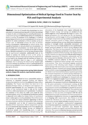
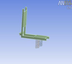
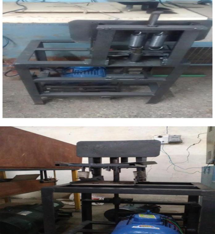
III. Two CAD models has prepared for this particular researchdependonthepositionofhelicalspringbyusing Pro EPlatform.TheModelsarepreparedinsuchwaythat,it willtakeallrealboundaryconditions.Fig.1showstheCAD Model Fig
Thisalloyspringsteelisusedforhighstressconditions andathightemperatureupto2200C.Itisgoodforfatigue resistanceandlongenduranceforshockandimpactloads.
ChromeSilicon.
Thismaterialcanbeusedforhighlystressedsprings.It offersexcellentserviceforlonglife,shockloadingandfor temperatureupto2500C.
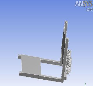
Fatiguelifeisdefinedasthenumberofstresscyclesof specifiedcharacterthataspecimensustainsbeforethefirst evidenceoffailure.IncaseofTractorseatroadirregularities andenginewillcauseavibrationwhichultimatelywillgive thefatigueinthehelicalspring.Hereforthisresearchwe have considered a vibration to be in completely reversed manner. So, for the fatigue life calculation we have to considerthefullyreversedcycle.
International Research Journal of Engineering and Technology (IRJET) e ISSN: 2395 0056
Meanstressvalue(��)=0
Stressamplitude(����)=200MPa
Endurancelimitofmechanicalacomponent(Se)
Se=Ka×Kb×Kc×Kd×Ke×Se'
Where,
Ka = Surface finish factor: The surface finish factor is depends on modes of surface finish operation. Due to complexgeometryofTractorseat,polishingisthebestway forfinishingofcrankcase.Forpolishingoperationvalueof surfacefinishfactorisone.
Kb=Sizefactor: Thesizefactordependsuponthesizeof cross section of the component. As the size of the component increases, the surface area also increases, resultinginagreaternumberofsurfacedefects.Ford>50, itsvalueis0.75.
Kc=reliabilityfactor: Thereliabilityfactordependsonthe reliabilitythatisconsideredinthedesignofcomponent.The reliabilityofthefatiguetestis50%.At50%reliabilitythe valueofreliabilityfactorisone.
Kd=Temperaturefactor: Temperaturefactordependson the temperature of component. Due to increase in temperatureendurancestrengthofcomponentdecreases. Itsvaluefortemperature550ºCis0.67.
Ke=Modifiedfactorforstressconcentration=1
Se'=Endurancelimit=0.45×Sut
Sut=2×Syt
Se=0.750×1×1×0.67×1×2Se‟
Fatiguestrength(Sf)=Nf����
FromS NdiagramasshowninFig2
CF/FB=AE/EB.
To find the problem of failure in tractor seat helical tensionspringsandtrytoreplaceitbyhelicalcompression springsusingstressandfatigueanalysis,theexperimental setupmadeisshowninfigure3
Fig.2S NDiagram
a)Helical
b)
Experimental setup is prepared for calculating the fatigue life of spring. The setup is prepared by using MS channelstructureandaseatoftractorismounted.Theseat isacceleratedbyusingelectricmotorof5hp.Acrankisused oflength40mmfortotalstrokeof80mm,tensionspringare placed at the back of seat .The seat is manufactured accordingthedesignofactualseatoftractorwhichisofMS. Two springs are placed at the back of seat the speed of output shaft is maintained as 500 rpm using rheostat at powerinputtoelectricmotor.
Two tension springs are mounted on the model and machineisacceleratedfordurationuptospringisgetting fracturedandfromobtainingtimethenumbersofcyclesare counted.
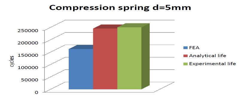
Experimental setup is prepared for calculating the fatigue life of spring. The setup is prepared by using MS channelstructureandaseatoftractorismounted.Theseat isacceleratedbyusingelectricmotorof5hp.Acrankisused
Volume: 09 Issue: 07 | July 2022 www.irjet.net p ISSN: 2395 0072 © 2022, IRJET | Impact Factor value: 7.529 | ISO 9001:2008 Certified Journal | Page2665
International Research Journal of Engineering and Technology (IRJET) e ISSN: 2395 0056
Volume: 09 Issue: 07 | July 2022 www.irjet.net p ISSN: 2395 0072
of length 40mm for total stroke of 80mm, compression spring are placed at the bottom of seat. The seat is manufacturedaccordingthedesignofactualseatoftractor whichisofMS.Twospringsareplacedatthebottomofseat. thespeed of output shaftis maintained as 500 rpmusing rheostatatpowerinputtoelectricmotor.
In these setup two compression spring of diameter 8mmand5mmaremountedatthebottomofseat.Machine is accelerated till the spring get fracture and number of cycles is calculated. Similarly same procedure is done for 5mmspringandnumberofcyclesiscalculated.
A. Stress analysis for three springs
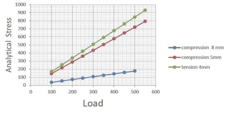
TableII Analyticalstressofspringsforvariableload Analytical stress Analytical stress Analytical stress Compression Compressio n Tension spring LOAD spring 8 mm spring 5 mm 4 mm (Mpa) (Mpa) (Mpa) 100 35.27963144 144.1468 169.175196 150 52.91944716 216.2202 253.762794 200 70.55926287 288.2936 338.350392 250 88.19907859 360.367 422.93799 300 105.8388943 432.4404 507.525588 350 123.47871 504.5138 592.113186 400 141.1185257 576.5871 676.700783 450 158.7583415 648.6605 761.288381 500 176.3981572 720.7339 845.875979 550 194.0379729 792.8073 930.463577
TableIIshowsanalyticalstressvaluesforthreesprings for various loading. And that can be used for further comparison. It was found that the stress produced in compressionspringofdiameter8mmislesserthanother twosprings
TableIII
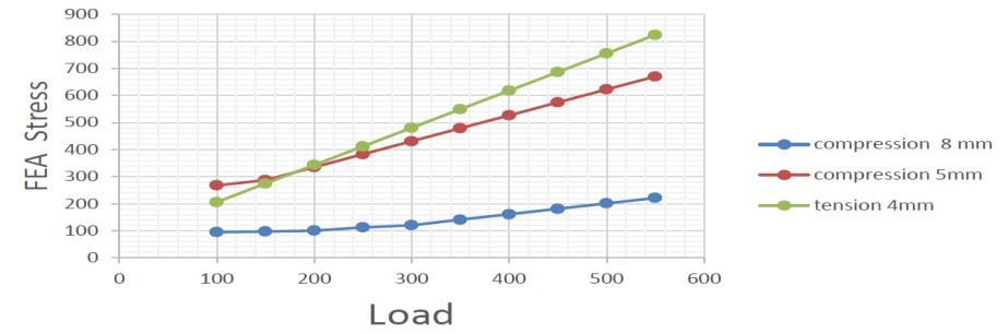
FEAstressofThreeSpringsforVariableLoads
LOAD
FEA STRESS Compression spring 8mm (Mpa)
FEA STRESS Compression spring 5mm (Mpa)
FEA STRESS Tension spring4mm (Mpa)
100 94.8810 268.020 205.8862276 150 97.397712 287.1218124 274.5149722 200 100.530283 334.975445 343.1437129 250 112.66285 382.8290845 411.7724551 300 120.79542 430.6827097 480.4012043
350 140.92799 478.5363478 549.0299445 400 161.06057 526.3899825 617.6586907
450 181.19314 574.2436247 686.2874337 500 201.32571 622.0972639 754.9161855
550 221.45828 669.9508899 823.5449103
TableIIIshowsFEAstressvaluesforthreespringsfor various loading. And that can be used for further comparison. It was found that the stress produced in compressionspringofdiameter8mmislesserthanother twosprings
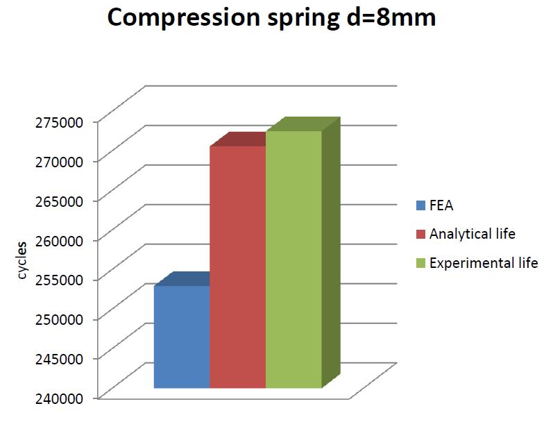
TableIVshowsthedifferenceinlifecycleforthree springsandvaluesdifferenceinAnalytical,Experimental, andFEAAnalysis.Itwasfoundthat lifecyclesofspring withdiameter8mmhavingbetterlifethanothertwo springs
TableIV Analytical,Experimental,FEAAnalysis
Spring Diameter Fatigue life Analytical Experiment al
Tension 4mm 189971.53Cycles 196000 cycles compression 5mm 244962.72Cycles. 250000 cycles compression 8mm 270582.68Cycles. 272500 cycles
International Research Journal of Engineering and Technology (IRJET) e ISSN: 2395 0056
Thefig.4showsthatcomparisonoftheFEAstressvalues forthreesprings.Anditisfoundthatstressproducedinthe compression spring of diameter 8mm is too lesser than othertwosprings.
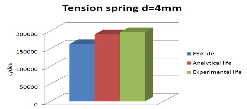
The fig.7 show that Comparison of fatigue life for compressionspringofdiameter5mm,experimentallyitis higher than other two analysis and FEA value shows too lesserascomparetoothertwovalues
Thefig5showsthatcomparisonoftheAnalyticalstress valuesforthreesprings.Anditisfoundthatstressproduced in the compression spring of diameter 8mm is too lesser thanothertwosprings.
Fig8Comparisonoffatiguelifeforcompressionspring d=8mm
The fig.8 show that Comparison of fatigue life for compressionspringofdiameter5mm,experimentallyitis higher than other two analysis and FEA value shows too lesserascomparetoothertwovalues
The fig 6 shows that Comparison of fatigue life for tensionspringofdiameter4mm,experimentallyitishigher thanothertwoanalysisbutitisnotoomuchvariation.
FatigueFailureanalysisofthebothmodelsshowsthe higherlifecycleinacompressionspringhelicalmodelthan tension helical spring also von misses stress of helical tensionishigherthancompressionmodelThetractorseat helicalcompressionspringwilllastlongerthanthehelical tension spring and also the stresses obtained in helical tensionspringaremuchhigherthanthecompressionspring model
Thanks to Prof. A.H. Karwande for his valuable contributioninperformingthisresearch.Aspecialthanksto Prof.B.C.LondheandmyHeadoftheDepartment,Prof.V.G. Bhamre for encouraging us for his support and guidance
International Research Journal of Engineering and Technology (IRJET) e ISSN: 2395 0056
throughoutandwithoutwhom,thiswork wouldhavenot beenpossible.Lastbutnottheleast;Iwouldliketothank the authors of the various research papers that I have referredto,forthecompletionofthiswork
[1]JinheeLee,“FreeVibrationAnalysisofcylindricalhelical spring By pseudospectral method”, „Journal of sound & Vibration‟,2007,302,185 196.
[2]A.M.YU,Y.Hao,“VibrationAnalysisofcylindricalhelical springwithnon circularcrosssection”,„Journalofsound& Vibration‟,2011,330,2628 2639.
[3]Mohamed Taktak, “Dynamic optimization design of cylindricalhelicalspring”„AppliedAcoustic‟,2014,77,178 183.
[4]K.MIchalczyk,“Analysisoftheinfluenceofelastomeric layer on helical spring stresses in longitudinal resonance vibration conditions”, „Archives of civil and mechanical engineering‟,2013,13,21 26.
[5]L.EBeckar,GGChassic,“Onthenaturalfrequenciesof helical compression spring”, „International Journal of MechanicalScience‟,2002,44,825 841.
[6]AiminYu.“Formulationandevaluationofananalytical studyforcylindricalhelicalspring”.„AMSS‟,2010,23,0894 9166.
[7] Youli Zhu, Yanli Wang, “Failure analysis of a helical compression spring for a heavy vehicle‟s suspension system”,2014,2,169 173
[8] Reza Mirzaeifar, Reginald DesRoches “A combined analytical, numerical, and experimental study of shape memory alloy helical springs”. „International Journal of SolidsandStructures‟,2011,48,611 628.
[9].DesignofmachineElement,V.B.Bhandari,Edition2001, TataMcGrawHill.
Volume: 09 Issue: 07 | July 2022 www.irjet.net p ISSN: 2395 0072 © 2022, IRJET | Impact Factor value: 7.529 | ISO 9001:2008 Certified Journal | Page2668