International Research Journal of Engineering and Technology (IRJET) e ISSN: 2395 0056

Volume: 09 Issue: 07 | July 2022 www.irjet.net p ISSN: 2395 0072
International Research Journal of Engineering and Technology (IRJET) e ISSN: 2395 0056
Volume: 09 Issue: 07 | July 2022 www.irjet.net p ISSN: 2395 0072
CH. Sudhakar1 , D. Sravya2
1PG Student, Department of civil Engineering, Velaga Nageswara Rao (VNR) College of Engineering, (Approved by AICTE and affiliated to JNTUK, Kakinada), G.B.C. Road, Ponnur 522124, GUNTUR, A.P (INDIA).
2Assistant Professor, Department of civil Engineering, Velaga Nageswara Rao (VNR)College of Engineering, (Approved by AICTE and affiliated to JNTUK, Kakinada), G.B.C. Road, Ponnur 522124, GUNTUR, A.P (INDIA). ***
Abstract The roofs of low rise structures are usually flat, pitched / gabled, hipped, or curved. Structures withcurved roof are being constructed to achieve largeunobstructedspans like entertainment centres, exhibition centres, sports arenas, airport hangers, etc. which are essential for various functional requirements.Thesestructuresaregenerallyconstructedeither at ground level or at an elevated level. Wind loads are considered to be one of the most important load criteria for the structural design of such structures. The aerodynamic behaviour and wind induced pressuresoverthecurvedroofsare being affected by major factors such as inflow characteristics such as mean velocity and turbulence intensity profiles, Reynolds number, surface roughness, angle of wind incidence, neighboring structures, size of tributary area and geometric proportionssuch as riseto span ratio, wall height to spanratio, length to span ratio and wall height to rise ratio. Based on the wind induced pressure information, database assisted design and equivalent static wind loading are used to establish wind loading for their structural design. Studies on the characteristics of wind pressure over curved roofs were reported over the last three decades. Based on the earlier studies, the riseto span ratio is observed to be significantly affecting the wind pressure on curved roofs. The side wall height to span ratio and building length to span ratio are the two other geometric proportions, which alsoinfluencethewind induced pressure on curved roofs, as reported in the literature. Further, mostof the studies reported in the literature were conducted under any one type of flow conditions, viz. uniform flow, open and suburban terrain conditions
Key Words: ABLWT,CFD,fabricationofcurvedroof,models curved roofs, Under uniform flow 2d and 3d pressures coefficients.
‘Wind’ or ‘air in motion’ usually creates a natural movementofairparalleltotheearthsurfacecreatingafast moving current. It is caused due to the variation of temperatureintheearth’satmospherewhichinturncreates pressuredifferences,makingtheairor‘wind’tomovefrom the high pressure region to the low pressure region. Further, due to the roughness of the earth’s surface, turbulentboundarylayerairflowstakeplacewithavarying gradientheightdependinguponthelengthofthefetchand the magnitude of thesurface roughness. These turbulent
boundary layer flows are characterized by randomly varyingwindvelocitiesandthepresenceofbuildingsinits waymakethewindflowtodeviatefromitsusualpath.In thecaseofhigh risebuildings,thewindwillpredominantly flowonbothsidesofthebuilding, whereas,inthecaseof low risebuildings,thewindwillpredominantlyflowover theroofofthebuilding.Since,low risestructurestopthelist of civil engineering constructionsa study on the effect of wind pressure on the roofs of these structures becomes mandatory.
Tostudythewindinducedpressureoveracurved roof with specific rise to span ratio and length to spanratio.
Tostudytheeffectofchangeinsidewallheightto span ratios on wind induced pressure over the curvedroof.
Tostudytheeffectofflowconditions,viz.uniform or open and suburban terrains, on wind induced pressureoverthecurvedroof.
Tostudytheeffectoftheangleofwindincidence,in the rangebetween wind normal to the axis of the roofandwindparallel totheaxisofroof,onwind inducedpressuresoverthecurvedroof.
In the present study, a wind tunnel pressure measurement on a curved roof structure with full-scale dimensions of length 135 m, span110.1 mand rise32.1m was considered. A scaled down ratio of 1:300 was consideredinordertoachievetheblockageratiolessthan 5 %. The details of dimensions of 2-Dimensional ‘2 D’ and 3Dimensional ‘3 D’ curved roof models (with and without walls) considered for wind tunnel experiments are given in Table-1. The curvature of the curved roof model considered in the present study is a circular arch with a radius of 0.21085 m and the subtended angleis 121 degree.
International Research Journal of Engineering and Technology (IRJET) e ISSN: 2395 0056
Volume: 09 Issue: 07 | July 2022 www.irjet.net p ISSN: 2395 0072
Table 1: Dimensions
Sl. No
Mod el cod e no.
Dimensions Geometric ratios Ris e, f (m)
Spa n, d (m)
Leng th, L (m)
Wall heig ht, h (m)
f/ d L/ d h/ d h /f
terrain conditions. Fordifferent wall height to spanratios and under each terrain condition, simultaneous pressures over the roof and wall were measured for angles of wind
data sets were acquired fora duration of 15 seconds with samplingfrequenciesof625HzbyPSIpressuretransducers and500HzbyScanivalvepressuretransducers.
0 0
2 SP0 3D 0 0 0
3 SP1 3D 0.05 35 0. 2 0. 5
1 AA0 3D 0.1 07 0.3 67 0.45
0 0. 3 1. 2
4 SP2 3D 0.10 7 0. 3 1
5 SP0 2D 0 0 0
6 SP1 2D 0.05 35 0. 2 0. 5
7 SP2 2D 0.10 7 0. 3 1
A3mmthickacrylicsheetwaschosenforthefabrication of the curved roof model. The sheet with required dimensions was placed in athermal cyclic chamber for heating.Afterheatingtotherequiredlevelofflexibility,the acrylicsheetwasplacedonthecementmortarsurfaceofthe bottom mould. The heated sheet was loaded with the top mould and, allowedit to cool under ambient conditions in ordertogettherequiredcurvature.Totally,twonumbersof curved roof models without the presence of walls were fabricated with the required dimensions of length, span and rise.
Piezoelectrictypedifferentialpressuretransducerswere usedinthewindtunnelinvestigationstomeasurethewind induced pressure fluctuations at high speed. These transducers measure the upstream dynamic pressure by measuring the pressure difference between the total pressureandstaticpressurefromapitot staticprobe.Two commercialmakesofpressuretransducerswereusedi.e.,PSI pressure transducers with 32 channels and Scanivalve pressure transducers with 32 / 64 channels. The PSI and Scanivalvepressuretransducersarecapableofcapturingthe pressures with sampling rate of 625 Hz and 500 Hz, respectively. The curved roof model AA0 3D was instrumented with area averaged pressure ports using manifolds of 10 numbers along the arch direction at two different locations, (i.e.,) at mid length and at half way betweenmid lengthandedgeoftheroof.
The 3 D curved roof models were instrumented with singlepointpressureportsandthepressuremeasurements were made under uniform, openterrain and suburban
This chapter presents the results of mean / standard deviation of pressurecoefficientsofthe2 D /3 Dcurved roofmodelsofwithheighttospanratioof0,0.15and0.29at two/threedifferentlocationsforvariousanglesof wind incidence under different terrain conditions. Further, comparison of the following results are also made and presentedinthefollowingsections.
Variation of mean Cp values obtained using area averagedpressureportsandsinglepointpressure ports over 3 D curved roofs under open and suburbanterrainconditions.
ComparisonofmeanCpvaluesobtainedfromthe windtunnelexperimentsandcodesofpracticeover 3 D curved roofs for wind direction normal and paralleltotheaxisofroofcases.
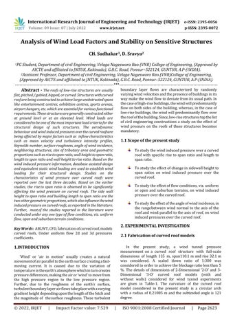
Pressure measurements on curved roof models were carried out using Atmospheric Boundary Layer Wind Tunnel (ABLWT) facility availableat CSIR Structural Engineering Research Centre (SERC),Chennai,India,whichisanopencircuitand blowertypewindtunnel.
The total length of the ABLWT is 52 m, with a long test section of 18 m. The test section has a widthof2.5mandheightof1.8m.
ThespecificationsoftheABLWTaregiveninTable 2.
The wire line diagram and the side view of the ABLWTare shown in Figures 3.12 (a) and (b).
The wind tunnel has two turn tables,oneonthe upstreamsideandanotheronthedownstreamside ofthetestsection,whichcanrotateat360 azimuth direction to achieve different angles of windincidence.
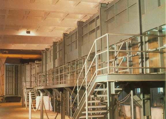
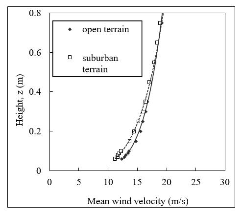
A uniform flow condition was achieved on the upstream side of the test section, whereas, a turbulentboundarylayerflowconditions(openand suburbanterrains)wereachieved.
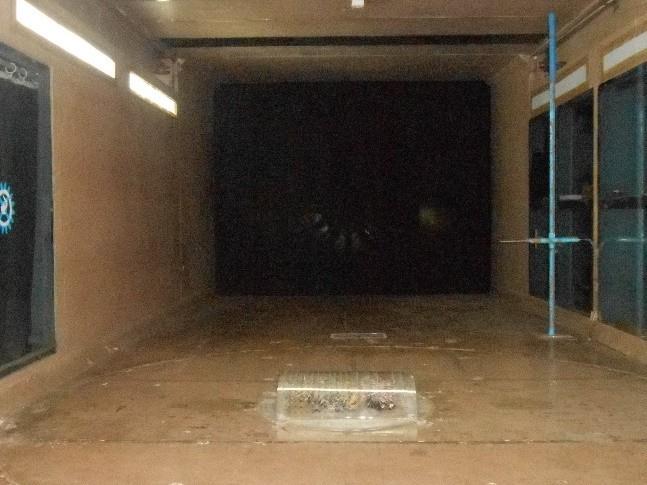
Thedownstreamsideofthetestsection,byblowing the wind over a trip board followed by a set of roughness boards, which were placed along the lengthofthetestsection.
2022, IRJET | Impact Factor value: 7.529 | ISO 9001:2008 Certified
International Research Journal of Engineering and Technology (IRJET) e ISSN: 2395 0056 Volume: 09 Issue: 07 | July 2022 www.irjet.net p ISSN: 2395 0072
Table 3: Detailsoninstrumentationscheme,anglesof windincidenceandterrainconditions
Sl.n o.
Mod el code no.
Type of pressu re port adopte d
Angle of wind inciden ce
Flow / terrain conditio ns
Transduc ers engaged
3 D / 2 D 1 AA0 3D
Area averag ed using manifol ds
0°to 360°in azimut h directio nwith 30° interval s includi ng diagona lwinds
Open and suburba n
2nos.of PSI 3 D 2 SP0 3D Single point
0°to 360° inazimu th directio nwith 30° interval s includi ng diagona lwinds
Uniform, open and suburba n
5nos.(2 nos.ofPSI +3nos.of Scanivalve )
3 D
3 SP1 3D 4 SP2 3D 5 SP0 2D Single point 0°only Uniform flow 12nos.of PSI 2 D 6 SP1 2D 7 SP2 2D
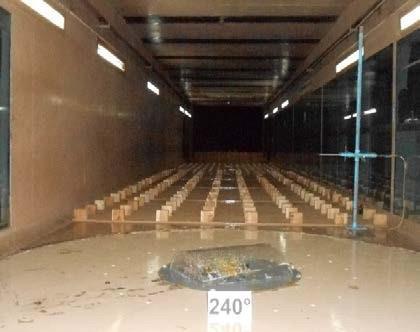
Fig 2 Uniformflow
International Research Journal of Engineering and Technology (IRJET) e ISSN: 2395 0056
Volume: 09 Issue: 07 | July 2022 www.irjet.net p ISSN: 2395 0072
Based on the literature on the wind induced pressuresanditseffectsoncurvedroofs,important issuetobestudiedwereidentified.
In the present study, wind tunnel pressure measurements on 2 D and 3 D models ofcurved roof were carried out under uniform flow, open andsuburbanterrainconditions.
Thecurvedroofhasarisetospanratioof0.29,a lengthtospanratioof1.23andwallheighttospan ratiosof0,0.15and0.29.
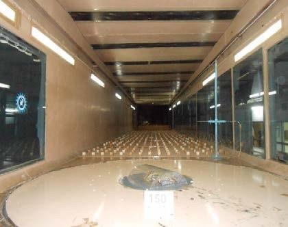
Fig-4 Suburbanterrain
Inthecaseof2 Dcurvedroofmodels,theinstrumented3 D curvedroofmodelwasusedforpressuremeasurementsby extendingitoneithersideto a length of 2.5 m, which is equal to the width of the wind tunnel testsection.These modelswereinstrumentedwithsinglepointpressureports atcentralregionoftheroofoveralengthof0.450mandno instrumentationwasmadeintheextendedportion.Pressure data setswereacquiredfora duration of18secondswith samplingfrequencyof650HzbyPSIpressuretransducers andforameanwindvelocityof16m/sunderuniformflow, measuredatalevelofthecrownheightofthemodelsSP0 2D, SP1 2D and SP2 2D, respectively. Pressures were measured for only one angle of wind incidence i.e., wind normaltoaxisoftheroofunderuniformflow.
The significance of wind induced pressures and their effectson cylindrical roofs under boundary layer flows were studied by various researchers using Atmospheric boundary layer wind tunnel (ABLWT).
Theeffectofwallheightandflowconditionsonthe distributions of mean andstandard deviation of pressurecoefficientsatedgeandmid lengtharches of the curved roof for various angles of wind incidencewereinvestigated.
Thevaluesofmeanpressurescoefficientsobtained from the experiment were compared with the valuesgiveninvariouscodesofpractice.Further,a patch load method has been formulated for computation of peak loads by using the distributions of mean and standard deviation of pressure coefficients obtained from the wind tunnelpressuremeasurements.
2 D and 3 D numerical simulations on curved roofs were carried out using Realizable k ShearStressTransportk obtainthepressuresexertedovertheroofunder uniformflow.
The values of mean pressures coefficients obtained from the numerical simulations were compared with the experimental values for validation.
Based on the wind tunnel experiments / Computational fluid dynamics (CFD) simulations carriedouton2 Dand3 Dmodelsofcurvedroof withdifferentwall heighttospan ratioof 0,0.15 and0.29underuniformflow,openandsuburban terrainconditions,thefollowingobservationsand conclusionsaremade.
The effect of wall height to span ratio over 2 D curved roofs is observed to be significantly pronouncedwiththemagnitudesofmeanpressure coefficients in the windward quarter region reducedwithincreaseinwallheighttospanratio.
The magnitudes of negative mean pressure coefficientsinthecenterhalfandleeward quarter increasedwithincreaseinwallheighttospanratio. On the leeward side the mean Cp values remain constantirrespectiveofwallheighttospanratio.
International Research Journal of Engineering and Technology (IRJET) e ISSN: 2395 0056 Volume: 09 Issue: 07 | July 2022 www.irjet.net p ISSN: 2395 0072
[1] AIJ RLB2004,ArchitecturalInstituteofJapan, Recommendationsforloadsonbuildings.
[2] AS/NZS: 1170.2 2011, Structural design actions, Part 2: Wind actions, Australian / New ZealandStandard.
[3] ASCE/SEI 7 05 2006, Minimum design loads for buildings and other structures, American SocietyofCivilEngineersStandard.
[4] Biagini, P, Borri, C & Facchini, L 2007, ‘Wind response of large roofs of stadions and arena’, Journal of Wind Engineering and Industrial Aerodynamics,vol.95,no.9 11,pp.871 887.
[5] Biswas, G & Eswaran, V 2002, Turbulent Flows:Fundamentals,ExperimentsandModeling, NarosaPublishingHouse,NewDelhi.
[6] Blackmore,PA&Tsokri,E2006,‘Windloads oncurvedroofs’,JournalofWindEngineeringand Industrial Aerodynamics,vol. 94,no.11,pp.833 844.
[7] Blessmann,J1998,‘Windloadsonisolatedand adjacent industrial curved roofs’, proceedings of the jubileum conference on wind effects on buildings and structures, eds. JD. Riera & AG. Davenport,PortAlegre,pp.137 171.
[8] Blocken, BJ, Carmeliet, J & Stathopoulos, T 2007,‘CFDevaluationofwindspeedconditionsin passages between parallel buildings effectof wall function roughness modifications for the atmosphericboundarylayerflow’,JournalofWind Engineeringand IndustrialAerodynamics,vol.95, no.9 11,pp.941 962.
[9] Bosch,G&Rodi,W1998,‘Simulationofvortex shedding past a square cylinder with different turbulence models’, International Journal for Numerical Methods in Fluids, vol. 28, no. 4, pp. 601 616.
[10]10. BS EN 1991 1 4:2005+Al:2010 2011, UK National Annex to Eurocode 1 Actions on structuresPart1 4:Generalactions Windactions, BritishStandards.
[11] Castelli, MR, Toniato, S & Benini, E 2011, ‘Numerical analysis of wind loads on a hemi cylindrical roofbuilding’,International Journalof Mechanical, Aerospace, Industrial, Mechatronic and Manufacturing Engineering, vol.8, no. 5,pp. 1669 1676.
[12] Cheng, CM & Fu, CL 2010, ‘Characteristics of wind loads on a hemispherical dome in smooth flowandturbulentboundary layerflow’,Journal of Wind Engineering and Industrial Aerodynamics,vol.98,no.6 7,pp.328 344.
[13] Cochran, L & Derickson, R 2011, ‘A physical modeller’s view of Computational Wind Engineering’, Journal of Wind Engineering and Industrial Aerodynamics, vol. 99, no. 4, pp. 139 153.
[14] Cook,NJ1990,‘Thedesigner’sguidetowind loading of building structures, Part 2: Static Structures,Butterworths,London.
[15] Davenport, AG 1967, ‘Gust loading factors’, JournaloftheStructuralDivision,ASCE,vol.93,no. 3,pp.11 34.
[16] Del Coz Díaz, JJ, García Nieto, PJ & Suárez Domínguez, FJ 2006, ‘Numerical analysis of pressure field on curved self weighted metallic roofsduetothewindeffectbythefiniteelement method’, Journal of Computational and Applied Mathematics,vol.192,no.1,pp 40 50.
[17] DelCozDíaz,JJ,GarcíaNieto,PJ,VilánVilán,JA, AlvarezRabanal,FP,Navarro Manso,A&Alonso Martínez, M 2013, ‘Nonlinear analysis of the pressurefieldinindustrialbuildingswithcurved metallic roofs due to the wind effect by FEM’, AppliedMathematics andComputation,vol. 221, pp.202 213.
[18] Ding,W,Uematsu,Y,Nakamura,M&Tanaka,S 2014,‘Unsteadyaerodynamicforcesonavibrating long spancurvedroof’,WindandStructures,vol. 19,no.6,pp.649 663.
[19] Ding, Z & Tamura, Y 2013, ‘Contributions of wind induced overalland local behaviours for internalforcesincladding supportcomponentsof large span roof structure’, Journal of Wind EngineeringandIndustrialAerodynamics,vol.115, pp.162 172.
[20] EN 1991 1 4: 2005+A1 2010, Eurocode 1: Actions on Structures Part 1 4: General actions Windactions,EuropeanStandard.
2022, IRJET | Impact Factor value: 7.529 | ISO 9001:2008 Certified Journal |