International Research Journal of Engineering and Technology (IRJET) e ISSN: 2395 0056

International Research Journal of Engineering and Technology (IRJET) e ISSN: 2395 0056
2
1
1
, Dr. P. K. Deshpande2
***
Abstract Cable Stayed Bridge are typical long spanbridge which are classified on the basis oflongitudinalandtransverse cable profile arrangements and pylon shapes. For the cable stayed bridge chosen for the current study, composite materials are intended to use such as Fibre Reinforced Polymer and Steel Reinforced Concrete which is then compared with conventional Precast Concrete deck and it's important to accuratelyevaluate the deckandpylon deflection and all the forces and stress characteristics of the structural elements of cable stayed bridge. Hence, dynamic evaluationof varied components of such bridges gains more importance due to their geometric complexity. So, the aim of the study is to develop most efficient type of composite Cable stayed bridge under the dynamic moving load and static windloadandtheir load combinations as per IRC and EN1991 1 4 respectively as these loads are dominating in a typical cable stayed bridge than seismic loads. A 3 span continuous cable stayed bridge with diamond shaped pylons is considered and modelled in FEM software Midas Civil 2019. The results are discussed in terms of pylon displacement, cable forces, bending moment, torsion of composite deck. The results concluded that Fiber Reinforced Polymer composites deck gives the less critical values and is most efficient as compared to the steelreinforced concrete and conventional precast concrete deck cable stayed bridge.
Key Words: Cable Profile Arrangement, Fiber Reinforced Polymer,SteelReinforcedpolymer,IRCLoadingsandtheir LoadCombinations,TypeofPylon
Cablestayedbridgesareaestheticallyattractiveandtheyare relativelylightweight,flexibleandlightlydampedstructure andhavelargerspanascomparedtogeneralbridges.Also, cablestayedbridgesexperiencemostflexibilitythannormal girderbridges.Thestructuralefficiencyanddesignofcable stayed is complex due to comprising of several structural components with individual stiffness and damping properties as both steel and concrete materials are in construction. Hence analysis of cable stayed bridges are done to estimate the dynamic response due to dynamic moving load and static wind load as the structure is light weight both the vehicular and the wind loads are
predominating.Therearetwomajorstructuraladvantages for achieving success in design of cable stayed bridges. Firstly,sincevarietyofcompactcablesisself anchoredinan exceedingly cable stayed bridge, massive scale anchorage isn't necessary as in an exceedingly conventional span. Secondly, the diagonally tensioned cables during a cable stayed bridge have greater rigidity and are less deflective than those of a suspension bridge, resulting in cost reductions.
For the cable stayed bridge designated for the current analysis, composites materials are used such as Fibre reinforced polymers and steel reinforced concrete. Nowadays,manymoreindustrieshavebroughtlightonall theprobabilitiesthatFibreReinforcedPolymercomposites must offer, aesthetically and structurally speaking. These composites prevail for an extended period long back but theirspecificuseofmaterialinindustriesiscurrent.Whenit involves the sector of bridge construction, alternatives to conventional materials, like steel, which mainly look after corrosion, fatigue, and also high maintenance problems. Thus, Fibre Reinforced Polymer composites research can statethatitisoneofthebetterreplacementscomparedto conventional. FRP provides certain betterment which are lesser self weight of the fabric, the dynamic effect of this compositebridgescanbecrucial.comparisonforthecable stayedbridgedesign,it's desirabletoalsodesigna bridge withtraditionalmaterials,duringthiscaseasteel concrete compositebridge.
(Khalifa et al. 1996) described the assorted analysis and designaspectsofafiberreinforcedplastic(FRP)bridge.The analysis is formed using three dimensional (3 D) macro modelsofthe bridge to explainitsoverall behavior under staticanddynamicloads. (Adanuretal.2011)studiedthe Fiberreinforcedpolymer(FRP)compositeswhichprovide many interesting features for existing and new bridges. Among these features are light weight, high stiffness to weightratioandstrength to weightratios,dampingabilities, and high resistance to environmental deterioration when properly designed and installed. (Xiong et al. 2011) introducednewformsofcable stayedbridgeswithcarbon fiberreinforcedpolymers(CFRP)staycablesand/oraCFRP deck.foreveryofthe2CFRPcomponents,namely,CFRPstay cablesandCFRPdeck,thekeydesignparametersandstyle
Volume: 09 Issue: 07 | July 2022 www.irjet.net p ISSN: 2395 0072 © 2022, IRJET | Impact Factor value: 7.529 | ISO 9001:2008 Certified Journal |
International Research Journal of Engineering and Technology (IRJET) e ISSN: 2395 0056
Volume: 09 Issue: 07 | July 2022 www.irjet.net p ISSN: 2395 0072
strategiesweredeterminedandthereforetheappropriate valueofeverykeydesignparameterwassuggested.(Choet al. 2013) observed the characteristics of axially loaded precastFRP concretecompositedeckswhichareexamined throughflexuraltestssoastoverifytheapplicabilitytocable stayedbridge.Thedeckofthebridgeisofcoursesubjected to high compressive forces. However, the precast Fibre ReinforcedPolymer concretecompositedeckflauntsalittle concretesectionopposingtocompression.
Fibrereinforcedpolymercompositematerialhastwomain structuralelementswhichareresinsandfibresitself.And, thepropertiesnotonlydependonthoseofitconstitutesbut alsoonthegeometryofFRPi.e.thefibretotheresinratio and the bonding between the two components also the directionofthefibres.
Fibrereinforcedpolymercompositewhichisalsocalledas fibre reinforced plastic composite which has two main structuralelementsoneisfibreandotherisresin.Property ofFRPnotonlydependsontheconstituentsusedbutalso dependsonthegeometryofcomposite,alsofibre resinratio, direction of fibres and the adhesions between two constituents.Inlongitudinaldirectionfibreshaveaveryhigh tensile strength thereby providing adequate stiffness and desiredmaterialstrengthtothefinishedproduct.Also,the capacityofUnidirectionallaminatesintransversedirection ismuchlesser.Thisstatesthatthestiffnessandstrengthof FRPmaterialdependonhowthefibresarealigned.These compositesaremadeupofhigh performancefibreswhich are embedded with a polyester matrix. Carbon, glass and aramidarethemostcommonlyusedfibresintheFRPand phenols, formaldehyde resins, polyester, vinyl ester and lastlyepoxy
FRPconsists ofhigh performancefibresembeddedwitha polymer matrix. Various fibres which are used in FRP are carbon, glass and aramid and polymers used are phenol formaldehyderesins,epoxy,vinylesterandlastlypolyesters
These composites can have different pattern of fibre arrangementwithinthepolymerwhichareasfollows.
1D orientation where the fibres are oriented in x directiononly;
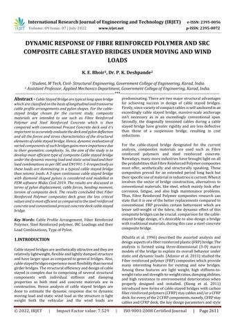
Figure 1. 3DFEMModellingofCablestayedbridge.
1.2 Bridge Configuration
Table 1: CompositeCablestayedbridgeconfiguration
Bridge type Fourspancablestayedbridge
Bridge length 46.5+113.5+260.0+100.0=520.0 m.
Bridge width 24.0m.
1.FRPCompositedeck.
Pylon shape
2.SRCCompositedeck.
3.ConventionalPSCdeck.
Diamondshape.
Number of cables 52×2pair=104.
Transverse arrangement Doubleplane. Number of lanes 6
There are 3 models which are considered for the current study.
1.Model1:FibreReinforcedPolymerdeckarrangementof CableStayedBridge
2.Model2:SteelReinforcedConcretedeckarrangementof CableStayedBridge
3. Model 3: Conventional Concrete deck arrangement of CableStayedBridge
2D orientation, where the fibres are aligned either oriented or in a particular manner in both x & y direction;
3 D arrangement, Where the fibres are randomly orientedinallthreedirectionsi.e.in(X,Y,Z)direction.
Model 1isoffibrereinforcedpolymerdeck ofspan520m andpylonheightof80m.MaterialpropertiesusedforFRP deck are mentioned in below table 2 and Anisotropic structuralpropertiesofcarbonfibrereinforcedpolymerare mentioned in table 3 and other material properties for compositecablestayedbridgearementionedintable4
International Research Journal of Engineering and Technology (IRJET)
e ISSN: 2395 0056
Volume: 09 Issue: 07 | July 2022 www.irjet.net p ISSN: 2395 0072
Name Type Elasticit y (kN/m2) Poisson ratio Thermal (1/[C]) Density (kN/m3)
Main Concret e
Sub Concret e
Mass Density (kN/m3 /g)
Material Type
Concret e 2.74E+0 7 0.167 1.00E 05 24.50 0.00 Isotropi c
Concret e 2.61E+0 7 0.167 1.00E 05 24.50 0.00 Isotropi c
Cable Steel 2.06E+0 8 0.3 1.20E 05 77.00 7.85 Isotropi c
CFRP Composi te 2.30E+0 7 0.18 1.8E 05 17.46 0.00 Anisotro pic
Name Type Elastici ty (kN/m 2)
Poiss on ratio
Therm al (1/[C] )
Densit y (kN/ m3)
A3 spancontinuousCableStayedBridgeisconsideredfor thestudywhichhave520moftotalspan(260mcentralspan and1st sidespansof160mand2nd sidespanof100m)and 80mofAsymmetricaldiamondshapedPylon.Thedeckis2 cell FRP & SRCsection of 24m wide and 1.6m depth. Two planesystemsoftransversearrangementofcableprofilesis considered.2numberofpylonsareplacedat260mcentre tocentrewith52numberofcablesateachpylon.
Mass Density (kN/m3 /g)
Material Type
Main Concrete Concrete 2.74E+ 07 0.167 1.00E 05 24.50 0.00 Isotropic
Sub Concrete Concrete 2.61E+ 07 0.167 1.00E 05 24.50 0.00 Isotropic
Cable Steel 2.06E+ 08 0.3 1.20E 05 77.00 7.85 Isotropic
CFRP User Defined 2.58E+ 07 0.32 1.96E 05 77.10 0.00 Anisotropi c
Model2isofsteel reinforcedconcretedeckof520mspan andwidthof24m.insteelreinforcedconcretesteelplatesof fe540areembeddedintotheconcretegradeofM45allthe material type and properties of steel reinforced concrete usedaregivenintable6
Material Type Standa rd DB Elastici ty (kN/m 2)
Poiss on
Therm al (1/[C] )
Loads to be considered while arriving at the appropriate combinationforcarryingouttheanalysisofFRP&SRCtype ofcompositecablestayedbridgeareasfollows:
1) Self Weight(DL).
2) SuperimposedDeadLoad(SIDL). 3) Pretensionforces. 4) MovingLoad(ML). 5) WindLoad(WL).
All the above loads are calculated as per IRC 6(2014) and wind load is calculated by EN1991 1 4 and applied to the FRP,SRCandPSCdecktypecablestayedbridgemodelsin FEMSoftware(MidasCivil2019).
Self weight is nothing but the total dead load of structure whichcontainssuperstructureandsubstructureelements. Girders,crossgirders,cables,andpylonaresuperstructure elements and the elements below the superstructure are substructurethatarepylonbelowthedeckandfoundation.
Densit y (kN/ m3)
Mass Density (kN/m3 /g)
SRC(Steel) IS(S) Fe5 40 2.05E+ 08 0.3 1.20E 05 76.98 7.85
SRC (Concrete) IS(RC) M45 3.35E+ 07 0.20 1.00E 05 23.60 2.41
Model 3 is of conventional precast concrete deck of same span and width as compared to model 1&2. Concrete of gradeM45isusedforpylonsanddeckandallthematerial typeandpropertiesofConventionalPSCisgiveninthetable below.
Name Type Elastici ty (kN/m2 )
Poiss on ratio
Therm al (1/[C])
Densit y (kN/m 3)
Mass Density (kN/m3/ g)
Additionaldeadloadsarenothingbuttheloadslikebarriers, footpathandkerbsetc.theseloadsaregenerallytakenas0.5 kN/m2
CalculationforSIDLisasfollows Assume,AsphaltDensity=2380kN/m2,WearingCoat=80 mm
SIDLLoad=23.8x0.08=1.904kN/m2
TotalSIDLLoad=1.904+0.5=2.404kN/m2
TotalWidthofDeck=24m
SIDLLoadalongdeck=24x2.404=57.70kN/m
Thetoplayerofaroadsurfaceiswearingcourse.The80mm ofwearingcourseisconsideredandappliedtothedeckas UDLbytaking22kN/m2.Theadditionalloadisappliedto thedeckasUDL.TheSIDLiscarriedoutduetocrashbarrier.
Material Type
Main Concrete Concre te 2.74E+ 07 0.167 1.00E 05 24.50 0.00 Isotropic
Sub Concrete Concre te 2.61E+ 07 0.167 1.00E 05 24.50 0.00 Isotropic
Cable Steel 2.06E+ 08 0.3 1.20E 05 77.00 7.85 Isotropic
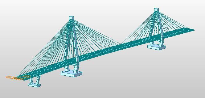
Theinitialstepofanalyzingacompositecable stayedbridge istocalculatetheinitialcableprestressingforcesfortheend bridgewithWCandSIDL.Thegeneralmethodoffindingout these initial prestressing forces is by the Unknown Load
IRJET | Impact Factor value: 7.529 | ISO 9001:2008 Certified
International Research Journal of Engineering and Technology (IRJET) e ISSN: 2395 0056
Volume: 09 Issue: 07 | July 2022 www.irjet.net p ISSN: 2395 0072
Factor (ULF) option in FEM software MIDAS Civil 2019 which is described in Figure 2. While performing linear analysisloadcombinationsfortheunitpretensionloadsand therespectivedeadloadshouldbedefined.
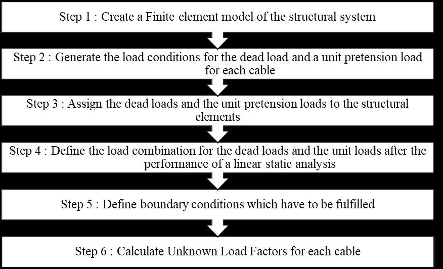
Theinitialcableforcesarecalculatedbydescribedmethod forFibrereinforcedpolymer,steelreinforcedconcreteand conventionalconcretedecktypeofcablestayedbridgesas showninFigure3.
Theseinitialcableforcesareappliedtoallmodel(FRP,SRC & PSC) types respectively with different load for further analysis.
Inapresentstudy,numberoflanesare6.Forthese6lanes,3 liveloadcasesaredescribedinCl.No.204.3,TableNo.2,IRC 6(2014).Theyare
1. CaseI:ClassA+Class70R 6Lanes.
2. CaseII:ClassA+Class70RWheeled left3Lanes.
3. Case III: Class A + Class 70R Wheeled right 3 Lanes.
The above moving load cases are defined with giving the trafficlinelanesaspertheireccentricityfromthecentreof deck.Theeccentricityoftheselanesiscarriedoutaccording to clearance distance from the deck, gauge distance and centretocentredistancebetweenvehiclesaspermentioned inClauseNo.204,IRC6(2014).
The basic wind velocity Vb is defined in EUROCODE (EN 1991 1 4) as a function of the wind direction and time of yearat23mabovegroundofterraincategory0.
Ze =23+0.8=23.8m
Thewindvelocityiscalculatedusingequation4.1section4.2
Where Vb,0 is the characteristic 10 minutes mean wind velocityat10mabovethegroundlevelforterraincategory II.WhichisdefinedinEN1991 1 4asthefundamentalvalue ofthebasicwindvelocity.
Figure 2. Flowchartforidealcableprestresscalculation
In the following calculations the basic wind velocity is consideredasVb =44.00m/s.
Thepeakvelocitypressure atheightzisgivenbythe expressionbelow;
Wind force acting in X direction
TheMovingloadsaredesignliveloadswhicharegiven in IRC6(2014).Thetermliveloadisnothingbuttheloadthat moves along length of the particular span. The loads are categorizedbasedontheirconfigurationandintensity.
1. DeckdeflectionduetoDynamicmovingload.
Composite Material used in the current study is FRP, steelreinforcedconcreteandconventionalconcrete.As theself weightofFRPisveryless,therebycausingvery fewer bending moments thus bending moment in the deckwasnotcritical.
2022, IRJET | Impact Factor value: 7.529 | ISO 9001:2008 Certified Journal
International Research Journal of Engineering and Technology (IRJET) e ISSN: 2395 0056
Volume: 09 Issue: 07 | July 2022 www.irjet.net p ISSN: 2395 0072
Tochecktheoveralldeflection,thedecksystemhereis designed as a single span beam on the supports. This wasdoneinMIDASCivil2019asitwasnotpossibleby handcalculation
Themaximumdeflectionislimitedto ,[NOTE:Lcan betakenasthelengthoftheclearspan]
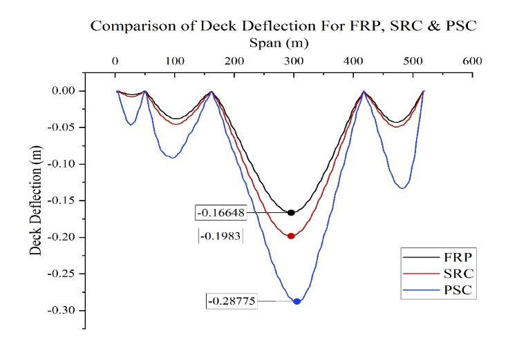
ComparisonofdeckdeflectionismadeofFRP,SRC,PSCdeck wereFRPdeckhaveleastdeflectionof0.173mfollowingwith theSRCandPSCof0.2mand0.29mrespectively.
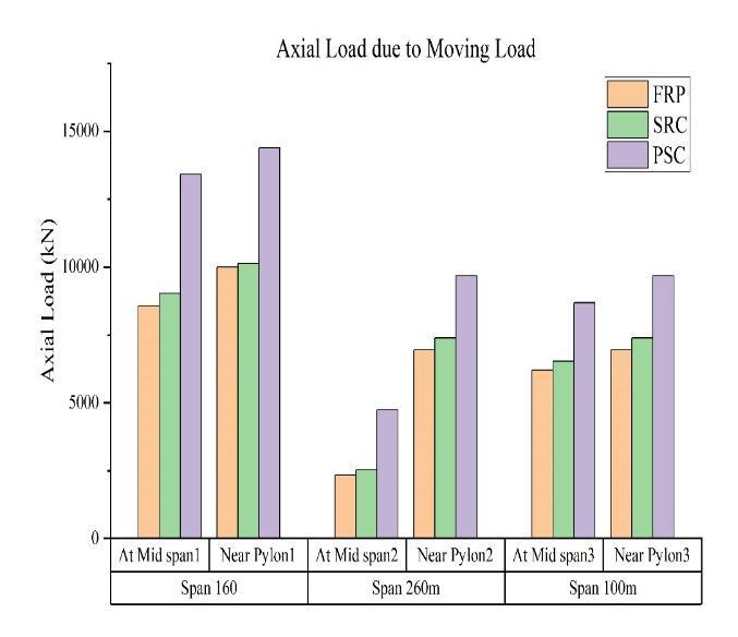
Figure shows maximumaxial forces generatedin the deck elements of FRP and SRC deck arrangements which are compressiveinnature.Themaximumaxialforceisoccurred in SRC arrangement followed by FRP deck. And when comparedwiththeconventionaldeckmaximumaxialforceis found out to be in PSC cable stayed bridge by increase of 43.8%
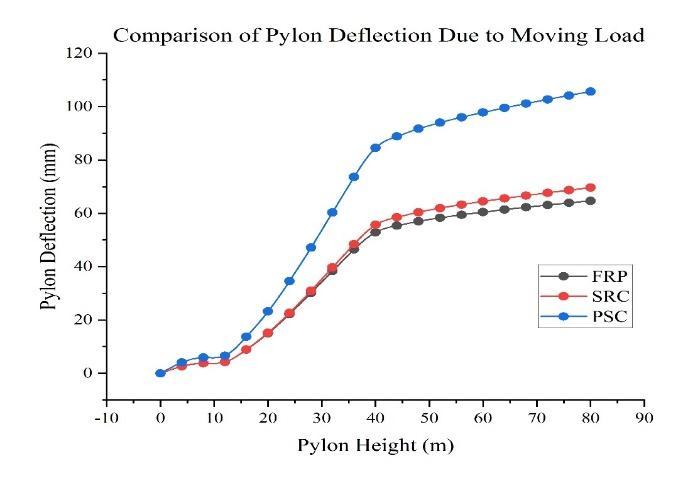
Intermsofdisplacementofpylon,thecomparisonismade betweenFibrereinforcedPolymer,SteelReinforcedconcrete and Precast Concrete deck of cable stayed bridge. Figure showsthemaximumdisplacementinpylonofFRP,SRCand PSCdeckcablestayedbridge.Themaximumdisplacementof deckisoccurredinconventionaltypeofcablestayedbridge of105.6539mm.Compositehavenearlyaround37.5%less valuesofpylondeflectionascomparedtoConventionalPSC cablestayedbridge.
Results for static wind analysis.
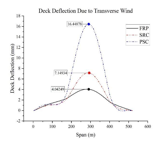
Deckdeflection.
Themaximumdeflectionislimitedto ,[NOTE:Lcan betakenasthelengthoftheclearspan]
ComparisonofdeckdeflectionismadeofFRP,SRC,PSC deck were FRP deck have least deflection of 4mm following with the SRC and PSC of 7mm and 16.3mm respectively. [NOTE All the deck have passed the maximumdeflectioncheck]
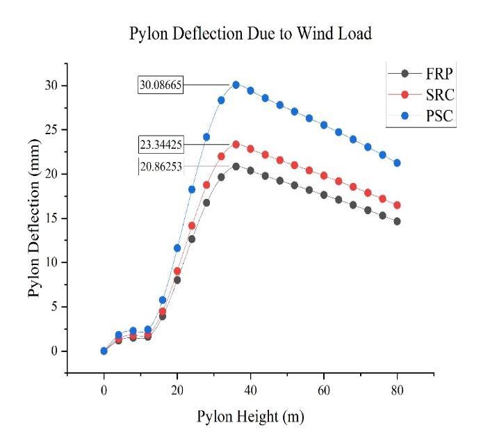
Pylondeflection.
Intermsofdisplacementofpylon,thecomparisonismade betweenFRP,SRCandPSCDeckofcablestayedbridgedue to static wind loads. Figure shows the maximum displacementinpylonofFRP,SRCandPSCdeckcablestayed bridge.Themaximumdisplacementofpylonisoccurredin conventional PSC type of cable stayed bridge of 30mm. Composite have nearly around 20% less values of pylon deflectionascomparedtoConventionaltypeofcablestayed bridge In Pylon, PSC cable stayed bridge has maximum displacement.
International Research Journal of Engineering and Technology (IRJET) e ISSN: 2395 0056
Volume: 09 Issue: 07 | July 2022 www.irjet.net p ISSN: 2395 0072
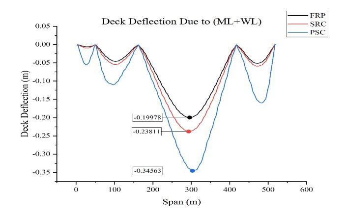
Asbothmovingloadandwindload incablestayedbridge are predominating thus combination of both moving load andwindloadresultsshouldbegovernedatthesametime.
Figureshowthedeckdeflectionalongthespanforboth themovingandwindloadcasesforFRP,SRCandPSC decks. Where, FRP deck have least deflection of 0.19978mfollowingwiththeSRCandPSCof0.23811m and 0.34563m respectively. [NOTE All the deck have passedthemaximumdeflectioncheck]
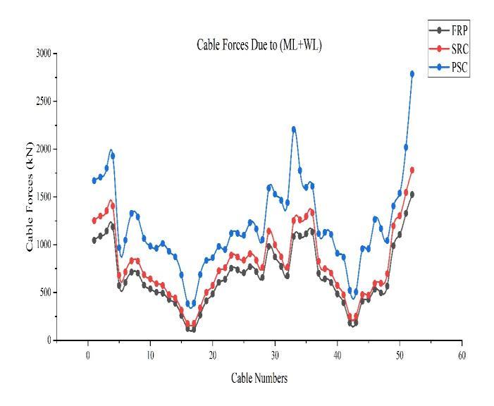
FigureshowsthecomparativeresultsbetweentheFRP,SRC andPSCdecktypeofcablestayedbridgeintermsofcable forcesduetobothmovingloadandwindload,bytakingall requiredloadsandloadcombinations,whichareoccurredin alltypeofarrangements.Themaximumcableforcearrivedin conventional deck type of cable stayed bridge which is of 2548.362kNComparativelylesservaluesofcableforcescan beseeninthecompositesused.
Composites have 31% lesser deck deflection as comparedtotheconventionalPSCcablestayedbridge.
For the deformation of pylon, the comparison is made betweenFibrereinforcedPolymer,SteelReinforcedconcrete and Precast Concrete deck of cable stayed bridge due to combinationofmovingandstatic windload.Figureshows the maximum displacement in pylon of FRP, SRC and PSC deck cable stayed bridge. The maximum displacement of pylonisoccurredinconventional PSCtypeofcablestayed bridgeof126.901mm.Compositehavenearlyaround32.11% lessvaluesofpylondeflectionascomparedtoConventional typeofcablestayedbridge.
International Research Journal of Engineering and Technology (IRJET) e ISSN: 2395 0056
Volume: 09 Issue: 07 | July 2022 www.irjet.net p ISSN: 2395 0072
Figureshowsthecomparisonofpylonreactionduetomoving loadandstaticwindloadwherethemaximumreactioncan beseeninPSCcablestayedbridgefollowingwiththeSRCand FRP deck bridges. This clarifies that the composite decks absorbthestressesefficientlyascomparedtoconventional cablestayedbridge.Also,incompositestheFibrereinforced polymer deck have relatively lesser values of support reactions than the SRC. Thus, making FRP best suitable compositesincablestayedbridge.
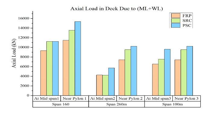
Figure 14. AxialLoadinDeckduetoML+WL
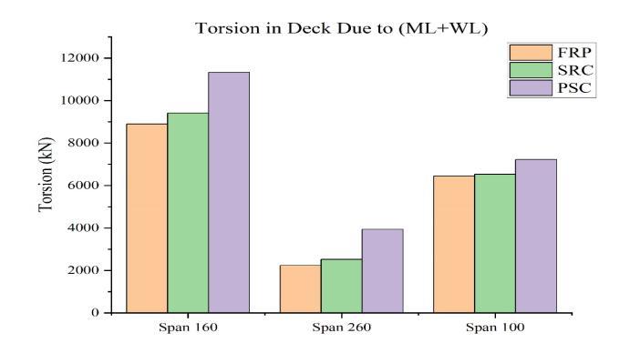
6. Torsionindeck.
Figure16showsthemaximumtorsionindeck.Themaximum torsionindeckisoccurredinPSCdeckfollowedbySRCand FRPdeckofcablestayedbridge.FRPdeckhas11.11%lesser valuesthanSRCand29.41%lesservaluesoftorsionindeck thanPSCdeck.
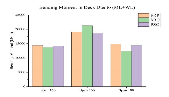
7. Bendingmomentindeck
Figure17showsmaximumbendingmomentoccurredinFRP, SRC&PSCcablestayedbridgeatrelativespanof160m,260 m,&100m.Themaximumbendingmomentoccurredisin SRCdeckfollowedbyFRP&PSCdeckofcablestayed.The bendingmomentinthedeckofSRChas11.56%morevalues thanFRP deck and14.28 %more values than PSC deck of cablestayedbridge.
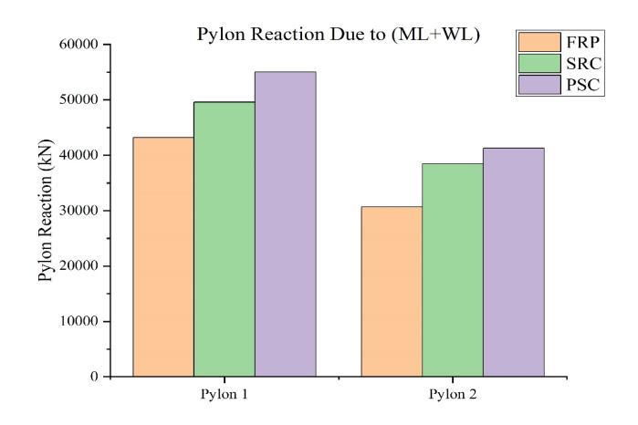
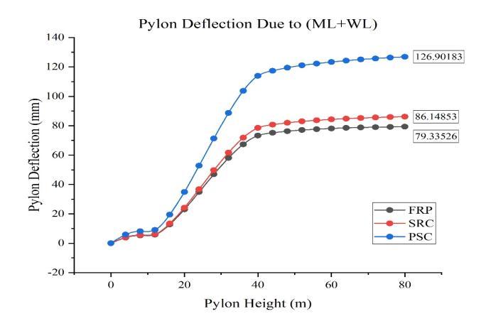
Figure shows maximumaxial forces generatedin the deck elements of FRP and SRC deck which are compressive in naturedue to movingand static wind load. The maximum axialforceisoccurredinSRCdeckfollowedbyFRPdeck.And whencomparedwiththeconventionalPSCdeckmaximum axialforceisfoundouttobeinPSCcablestayedbridgeby increaseof43.8%.Thus,statingthatFRPdeckrelativelyhas lesservalueofaxialloadgeneratedindeck
Figure 16. TorsioninDeckduetoML+WL
International Research Journal of Engineering and Technology (IRJET) e ISSN: 2395 0056
Volume: 09 Issue: 07 | July 2022 www.irjet.net p ISSN: 2395 0072
bridges using finite element method.' Computers & Structures, 80:13,1145 58.
[3] Cho,K.,Park,S.Y.,Kim,S.T.,Cho,J. R.&Kim,B. S.2013. 'Behavioral characteristics of precast FRP concrete compositedecksubjectedtocombinedaxialandflexural loads.' Composites Part B: Engineering, 44:1,679 85.
[4] Haifan, X., Jiming, X. & Zhixin, L. 1988. 'Aerodynamic study on a proposed cable stayed bridge in Shanghai, China.' Journal of Wind Engineering and Industrial Aerodynamics, 29:1,419 27.
Figure 16. BendingMomentinDeckduetoML+WL
Themaximumvaluesforallstructuralentitiessuchas deck and pylon deformation, axial loads in the deck, pylonreaction,cableforceswhichareconsideredforthe presentstudy,areobtainedinFRP,SRCandPSCtypeof cablestayedbridge.Fibrereinforcedpolymerdeckcable bridge has always lesser values than the maximum. Thus, it can be concluded that FRP deck type of cable stayedbridgeismostefficientstructurethanSRCand PSCcablestayedbridgeforlargespans.
Therigidityofsteelreinforcedconcretedecktypecable stayedbridgeismoreduetotheirmaterialstiffnessand complexity which increases bending moment in deck and pylon and frequency of the structure. However, torsion in FRP deck arrangement is less due to their inherentmaterialproperties.
Thetorsional stiffnessoftheFRPdeck exhibitsbetter resultsascomparedtotheSRCandPSCdeck.
Moving and static wind load which are dominating in cablestayedbridgesplaysavitalroleindesigningcable stayed bridge were FRP composites has given better resultsthanSRCcompositeandtraditionalconcrete.
As fibre reinforced polymer composite deck have far betterresultsthansteelreinforcedconcreteandprecast concreteitcanbeconcludedthatFRPisbestsuitedas compositematerialforcablestayedbridge.
[1] Adanur,S.,Mosallam,A.S.,Shinozuka,M.&Gumusel,L. 2011. 'A comparative study on static and dynamic responses of FRP composite and steel suspension bridges.'30:15,1265 79.
[2] Cheng, J., Jiang, J. J., Xiao, R. C. & Xiang, H. F. 2002. 'Advanced aerostatic stability analysis ofcable stayed
[5] Hong, T. & Hastak, M. 2007. 'Simulation study on construction process of FRP bridge deck panels.' Automation in Construction, 16:5,620 31.
[6] Jones, N. P. & Scanlan, R. H. 2001. 'Theory and Full BridgeModelingofWindResponseofCable Supported Bridges.'6:6,365 75.
[7] Khalifa,M.A.,Hodhod,O.A.&Zaki,M.A.1996.'Analysis and design methodology for an FRP cable stayed pedestrianbridge.' Composites Part B:Engineering, 27:3, 307 17.