2
International Research Journal of Engineering and Technology (IRJET) e ISSN: 2395 0056

Volume: 09 Issue: 07 | July 2022 www.irjet.net p ISSN: 2395 0072
2
International Research Journal of Engineering and Technology (IRJET) e ISSN: 2395 0056
Volume: 09 Issue: 07 | July 2022 www.irjet.net p ISSN: 2395 0072
***
Abstract: This paper examines two performance analyzes Stage photovoltaic (PV) system integrated with shunt Active harmonic filter (SAHF). In the recent industrial revolution Distributed generation systems are affected by current harmonics Problems due to the widespread use of non linear loads. The shunt Active harmonic filter system has harmonic relaxation, power factor correction, and load balancing. shunt Active harmonic filter system 3 leg voltage source converter and extracted DC current From the PV module. In this two layer system, the first layer is Maximum mounted DC DC boost converter Maximum power point tracking (MPPT) algorithm. To extract the maximum performance P & O algorithm is used. Extraction Reference current is obtained by PI controller and hysteresis A current regulator is used to control the PWM VSI. Predict PV based SAHF is implemented under the load of a diode rectifier Attenuates harmonics and reactive power
Keywords: P&O algorithm based MPPT; hysteresis controller; instantaneous real power theory; PV system grid integration; power quality.
Fossilfuelshavebeenamajorsourceofenergyformany years, but they have some problems because they are finite, depleted and non recyclable. They also make It pollutes and leads to global threats such as global warming.Therefore,theglobaltrendistoshiftgenerations tocleanerandmoresustainabletechnologiesastheygrow [1] [3]. Due to the advancement and popularity of PV based systems as an alternative to traditional energy sources, PV based systems are widely used in a variety of applications. As power electronics devices and non linear loads become more prevalent, harmonics are introduced intothesystem.AccordingtotheIEEEstandard512 2014, most electrical equipment works well if the total harmonicsdonotexceed5%[4].Passivefilters havebeen widely used to reduce harmonics, but they have some
drawbacks. This causes resonance problems in the networkandtendstocomplicatethedesignasthenumber of harmonics removed increases. PV based APFs are becoming more popular because they can be removed. Harmonics from the converted DC power of the PV module. The cost of installing a PV system is very high, so itisadvisabletogetthemaximumperformancefromyour PV system. It is integrated with the MPPT algorithm to ensure maximum efficiency of the PV system. Modeling a PVsystemusingMPPTtechnologyisdescribedin[5].
Inarealsystem,thequalityofpowerreceivedfromPV APF depends on several factors, including: B. Irradiance, temperature, and how to configure the PV system. Many researchers use inverters to analyze the behavior of PV APF based systems in various configurations. [6] analyzes the performance of PV APF based systems with different configurations based on SIC, MSIC, and CIC. In [7], the three phase PV system is designed with an integrated Universal Power Quality Conditioner (UPQC). This has the added benefit of both series and shunt compensators, and can provide voltage regulation and harmonic compensation, a d q based moving average filter. Use of theoretical control base. In [8], researchers used UPQC to analyzetheperformanceofPVsystemsunderdynamicand staticconditions.Itisused totrack thecontrol strategy of the variable irradiance feed forward control loop (FFCL). [9] proposes a multipurpose lattice wave digital filter (LWDF) PV system that can inject active power, provide grid balancing, and reduce load harmonics. In [10], a two stage PV system using the attenuation second order generalized integrator algorithm is proposed. In [11], the control method based on the general purpose notch has beenimproved.
A filter has been proposed and this scheme can extract thebasiccomponentsoftheloadcurrentregardlessofthe line voltage. In [12], researchers proposed a three phase series hybrid active filter (SEHAF) integrated into a PV
International Research Journal of Engineering and Technology (IRJET) e ISSN: 2395 0056
Volume: 09 Issue: 07 | July 2022 www.irjet.net p ISSN: 2395 0072
system.ThisschemeisfurtheranalyzedusingbothPIand fuzzylogiccontrol. [13]withnewMPPTtechnologybased onperturbationsandobservations
It employs a control scheme based on a maximized M Kalman filter, which has proven to be faster and more accurate than traditional P & O. In [14], researchers analyzed the performance of PV systems integrated with universal secondary sequential active filters. This method isbased onproportional resonance control. The proposed method extracts the basic active ingredients very accurately from a distorted and unbalanced load with Mathematicalcalculation.
Inthispaper,wecombinethePVmodulewithanactive shunt powerline conditioner and analyze its performance based on various parameters. This algorithm does not require a synchronization algorithm to synchronize the injected referencecurrent tothesupplyvoltage,soituses the instantaneous active power theorem to extract the reference current. It draws DC current from the power supply and compares it to a fixed voltage with either a PI controller or a fuzzy logic controller. Converts the extracted reference current and DC. Pulse Width ModulationHysteresiscontroller,thecurrentabsorbedby thefiltertoswitchgatepulses.TheP&Oalgorithmisused to track the maximum operating point of the PV module. Therefore, Section II introduces the generalized PV model anditsproperties,alongwiththegeneralizedactivepower filter model. It also describes the combination with the selected MPPT topology. Section III describes a proposed PV system model with an active shunt harmonic filter. Section IV analyzes the performance of the proposed configuration with and without SAHF in the MATLAB / SimpowerSystems environment. Finally, the conclusions aregiveninSectionV.
TheoutputofthePVmoduleisDCandisconnectedtoa DC DC boost converter to provide a voltage level suitable for shunt Active harmonic filter systems. Shunt AHF has proven to be an effective way to eliminate harmonics by injecting an AC current that is as large as the harmonics. 180 ° out of phase, removing harmonics from the source current.
A photovoltaic system consists of solar modules that convertthelightenergyofthesunintoelectricalenergyby the photoelectric effect. The equivalent circuit of a solar cell
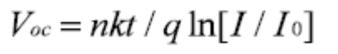
WhereRse andRsrepresentseriesresistanceandshunt resistance, as shown in Figure 1 (a). The V and P V characteristics are shown in Fig. 1 (b) and Fig. 1 (c), respectively. The Vmp, Imp, and Pmax points represent the maximum power points of the PV cell for maximum cell efficiency.
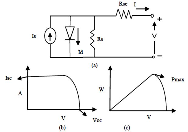
Fig.1.(a).SimplifiedequivalentcircuitdiagramofPVcell (b)I VcharacteristicsofPVcelland(c)P Vcharacteristics ofPVcell
ThediodecurrentgivenbyShockley'sequationis:
(2.1)
WhereIsis theinversesaturationcurrent,qisthecharge carrier (1.6 x 10 ^ 19 C), K is the Boltzmann constant (1.380649x10^ 23),nistheidealcoefficient(1),andTis thecell.temperature(25°C).Twolimitingcomponentsof thePVmodule,i.H. Voc and Isc determineEq.(2.1)byfirst settingV=0togettheIscandthensettingthecellcurrent I=0Eq2.1leadsto:
(2.2)
The performance of solar cells depends on the amount ofsolarradiation.TheMPPTtrackingalgorithmisused to ensure that the PV system is operating at maximum
International Research Journal of Engineering and Technology (IRJET) e ISSN: 2395 0056
Volume: 09 Issue: 07 | July 2022 www.irjet.net p ISSN: 2395 0072
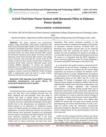
efficiency. The maximum stress point is obtained by the followingequation
(2.3)
Theformfactor,whichisameasureofthequalityofcell connections,isgivenbythefollowingformula: (2.4)
The conclusion that the value of the form factor is high is quality. Finally, the efficiency of the PV module is given by: (2.5)
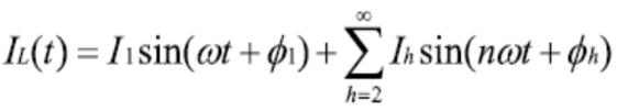
Non linear loads introduce a harmonic component that is an integral multiple of the basic component of the current. SAHFcancelstheharmonicsbyinjectingacurrent thatisthesamemagnitudeastheharmonicsbut180°out of phase, and cancels the harmonics so that the load current is free of harmonic components. This algorithm hastheadvantagethatitdoesnotrequiresynchronization with the phase voltage. The reference current and the current required to set the intermediate circuit capacitor are then converted into switching pulses via PWM performedbythehysteresiscontroller.
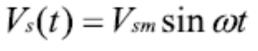
Thecurrentsupplyvoltageisasfollows. (2.6)
ThesourcecurrentisgivenbynodeanalysisinthePCC. (2.6)
IL(t)isloadcurrent (2.7)
Here, the second term is the harmonic component. The instantaneous value of load power can be calculated from the load current and supply voltage. Total load power is
calculatedas:
(2.8)
Active power comes from the load power given as follows: (2.9)
Thesourcecurrentaftercompensationis (2.10)
Fig.2.(a).SchematicdiagramofSAHFand(b).SAHF waveform
HARMONIC
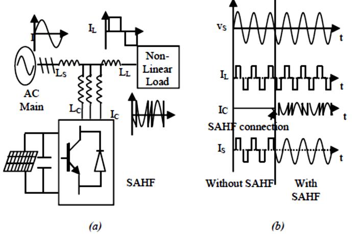
Figure3showsablockdiagramofthePVSAHFsystem.A PV array system with a P & O MPPT controller powers a shunt Active harmonic filter system connected to a non linearloadinashuntconfiguration.shuntActiveharmonic filter is implemented using a PWM VSI controller. An adaptive hysteresis controller is implemented to generate VSI switching pulses. The PI controller extracts the referencecurrent.Thisextractedreference currentisthen compared to the power supply current to generate a switching pulse. Non linear loads introduce harmonic components into the supply current. Shunt Active harmonic filter produces a transient current that is as large as the source current, but its phase is 180 ° out of phase, canceling out the harmonics present in the source current to make it a sine wave and in phase with the source voltage. increase. Compensation current is
International Research Journal of Engineering and Technology (IRJET) e ISSN: 2395 0056
Volume: 09 Issue: 07 | July 2022 www.irjet.net p ISSN: 2395 0072
generated by detecting the reference current obtained fromthesupplynetwork.
The DC DC boost converter consists of an IGBT controlled by a PWM signal generated by the MPPT controller. It consists of two energy storage elements, a conductorandaninductor.Whentheswitchusedwiththe IGBT is closed, current flows through the inductor and charges the inductor by creating a magnetic field. When the switch is open, the current is reduced. The energy of the generated magnetic field is reduced to maintain the load current. Therefore, the polarity of the inductor is reversed.Asa result, the twosources are placedinseries, increasing the voltage that charges the capacitor through the diode. The output of the DC DC boost converter is as follows:
(3.1)
WhereVoistheoutputvoltage,Vsistheoutputvoltageof the PV module, and D is the duty cycle of the boost converter.
The PV cell performance depends on solar irradiance. TheMPPTtrackingalgorithmisusedtoensurethatthePV systemisoperatingatmaximumefficiency.maximum
Stresspointsareobtainedinthefollowingways.
(3.2) Thus (3.3)
WhereVmp isthemaximumpowerpoint voltage, Kis the Boltzmann constant, q is the charge carrier, T is the temperature in Kelvin, and Voc is the open circuit voltage of the PV module. The increased power from the PV module is DC power, which is passed to the DC AC converterforusebytheutility.
This model uses a three phase bidirectional DC / AC converter consisting of six branch switches. The three arms of the inverter are delayed by 120 ° to generate three phaseACpower.The 3 armVSIsolid stateswitchis controlled by PWM pulses generated by the shunt Active harmonicfiltercontroller.
The PI controller is used to extract the reference current. The three phases of supply current are evaluated using a unit sine vector template that is homeomorphic to the source voltage. The unit sine vector template is given as follows:
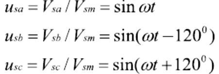
(3.4)
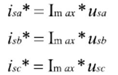
The PI controller evaluates Imax, which is the magnitude of the peak reference current. Multiply the weighted peak current by the unit sine template output to produce the desiredreferencecurrent.
(3.5)
The PWM VSI hysteresis controller is used to generate switching pulses, and the hysteresis controller changes rapidly between the two stages depending on the permissiblehysteresisband,suchas:
:(3.6)
The lower switch is turned on to generate a negative voltageandincreasetheloadcurrent
(3.7)
Thetopswitchisturnedontogenerateapositivevoltage andincreasetheloadcurrent
Fig.3:SimulatedmodelofgridtiedPVsystemwith harmonicfilter
International Research Journal of Engineering and Technology (IRJET) e ISSN: 2395 0056
Volume: 09 Issue: 07 | July 2022 www.irjet.net p ISSN: 2395 0072
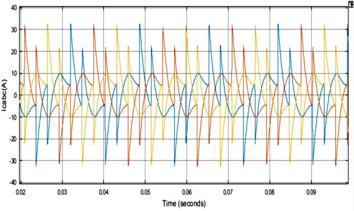
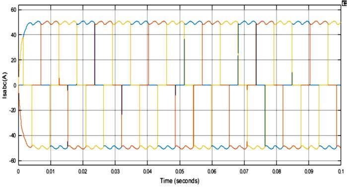
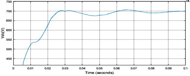
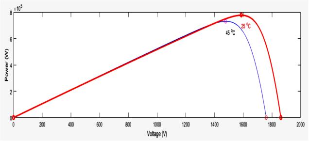
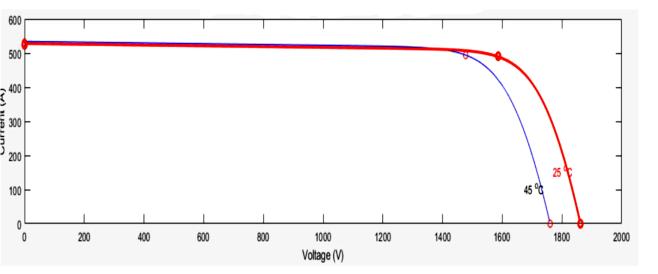
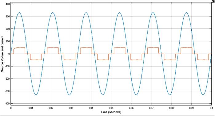
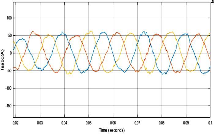
TheGrid TiedSolarPowerSystemwithHarmonicFilter to Enhance Power Quality system has been tested with MATLAB / Simulink software. The PV array powers the SAHF, which produces an equilibrium current from the referencecurrentdrawnfromthegrid.Figure1showsthe P V and I V characteristics of the PV array at cell temperaturesof25°Cand45°C.4(b)orFigure4(a).The points obtained in the graph correspond to the maximum power points of the PV array. The P / O MPPT based controllerworksatthispointtomaximizetheefficiencyof the PV array system. From the characteristic curve, it can be seen that as the temperature rises, the short circuit current increases, but the open circuit voltage decreases. Figure 5 (a) shows the source current in the supply network without the harmonic filters integrated in the shunt configuration. From this figure, it can be seen that the source current contains higher order harmonic components in addition to the fundamental wave components due to the non linear load. The PWM VSI produces a compensating current to attenuate the harmonic components, as shown in Figure 5 (b). Compensatedcurrentsthatarethesamemagnitudeasthe harmonic components but 180 ° out of phase cancel the harmonics. Figure 5 (c) shows the source current after integrating Shunt Active harmonic filter. This shows that the source current is a sine wave and harmonics are mitigatedeffectively.
(a)
(b)
Fig.4.(a)I V(b)P VcharacteristicsofPVarrayand(c) Vdc (a) (b)
International Research Journal of Engineering and Technology (IRJET) e ISSN: 2395 0056
Volume: 09 Issue: 07 | July 2022 www.irjet.net p ISSN: 2395 0072
(c)
Fig.5.Sourcecurrent(a)withouttheconnectionof harmonicfilter(b)compensatingcurrentand(c)with connectionofharmonicfilter (a) (b)
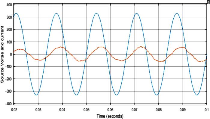
Fig.6.(a)PowerfactorWithoutIntegrationofHarmonic Filter(b)Powerfactorimprovementaftertheintegration ofHarmonicFilter
(a) (b)
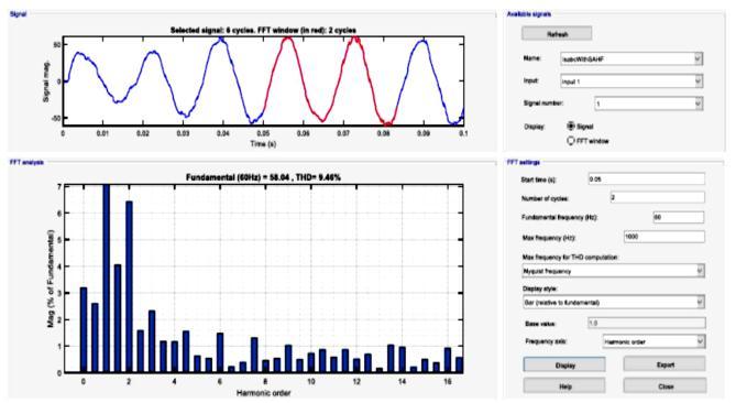
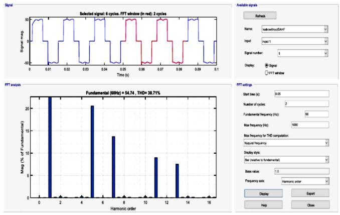
Fig:7THDpresentinsourcecurrent(a)withoutharmonic filter(b)Withharmonicfilter
The performance of the Grid Tied Solar Power System with Harmonic Filter to Enhance Power Quality system is analyzed. P & O based MPPT technology faster than time domain approach Implemented successfully with boost converter. Shunt Active harmonic filter is implemented using a PWM VSI controller. An adaptive hysteresis controller is implemented to generate the switching PWM VSI pulse. The PI controller is used to draw the reference current. The PI control method was used to control the reference current by controlling the DC voltage obtained from the PV array system. Describes the concept of Shunt Active harmonic filter and the characteristics of harmonic componentsandcompensationcurrent.
Theperformanceof Grid TiedSolarPowerSystemwith HarmonicFiltertoEnhancePowerQualitysystemsystems has been analyzed under various operating conditions in the MATLAB / Simulink environment. The harmonic
International Research Journal of Engineering and Technology (IRJET) e ISSN: 2395 0056
Volume: 09 Issue: 07 | July 2022 www.irjet.net p ISSN: 2395 0072
content is well below the specified IEEE standard of 5%. The shunt configuration of the SAHF system not only reduces harmonics, but also improves the power factor. Theproposedconfigurationischeapandeasytoassemble becauseitrequiresfewersensors.
[1] L. Hassaine, E. Olias, J. Quintero, and M. Haddadi, "Digital power fac tor controland reactive power for grid connected photovoltaic inverter" Renewable Energy34(2009)315 321.
[2] N. Hamrouni. M. Jraidi, and A. Cherif. "New control strategyfor2stagegridconnectedphotovoltaicpower system. "Renewable Energy, vol. 33, no. 10, pp.2212 2221,2008.
[3] M. G. Villalva, J. R. Gazoli, and E. R. Filho, "Comprehensiveapproachtomodelingandsimulation of photovoltaic arrays," IEEE Trans. Power Electron., vol.24,no.5,pp.11981208,May2009.
[4] IEEE Standard 519. IEEE recommended practice and requirement for harmonic control in electric power systems. In IEEE Std 519 2014 (Revision of IEEE Std 519 1992);IEEE:Piscataway,NJ,USA,2014;pp.129.
[5] P. Sharma, S. P. Duttagupta, and V. Agarwal. "A novel approach for maximum power tracking from curved thin film solar photovoltaic arrays under changing environmentalconditions."IEEETrans.Ind.Appl.,vol. 50,no.6,pp.41424151,Nov./Dec.2014.
[6] H. Patel V. Agarwal "Investigations into the performance of photovoltaics based active filter configurations and their control schemes under uniform and nonuniform radiation conditions. "IET Renewable Power Generation, vol. 4 pp. 12 22, January2010.
[7] Sachin Devassy, Bhim Singh "Design and Performance Analysis of Three Phase Solar PV Integrated UPQC." IEEE TRANSACTIONS ON INDUSTRY APPLICATIONS, VOL.54,NO.1,pp.73 81.
Bhim Singh, Shailendra Kumar, Chinmay Jain "Damped SOGI Based Control Algorithm for Solar by Power Generating System IEEE TRANSACTIONS ON INDUSTRY APPLICATIONS, VOL. 53, NO. 3, pp. 1780 1788,MAY/JUNE2017
[8] Vandana JainBhimSingh "AMultipleImprovedNotch Filter BasedControlforaSingle StagePVSystemTied to a Weak Grid." IEEE TRANSACTIONS ON SUSTAINABLE ENERGY, VOL. 10, NO. 1, pp. 237 248, JANUARY2019
[9] Prakash K. Ray, Soumya Ranjan Das, Asit Mohanty "Fuzzy Controller Designed PV Based Custom Power Device for Power Quality Enhancement," IEEE TRANSACTIONS ON ENERGY CONVERSION, VOL. 34, NO.1,pp.405 415,MARCH2019.
[10]Nishant Kumar, Bhim Singh, Bijaya Ketan Panigrahi "Integration of Solar PV With Low Voltage Weak Grid System: Using Maximize M Kalman Filter and Self Tuned P&O Algorithm," IEEE TRANSACTIONS ON INDUSTRIAL ELECTRONICS, VOL. 66, NO. 11, pp. 9013 9022,NOVEMBER2019.
[11]SachinDevassy.BhimSingh "ImplementationofSolar Photovoltaic TRANSACTIONS ON INDUSTRY APPLICATIONS,VOL.55,NO.4,pp. 3926 3934,JULY/AUGUST2019