International Research Journal of Engineering and Technology (IRJET) e ISSN: 2395 0056

Volume: 09 Issue: 07 | July 2022 www.irjet.net p ISSN: 2395 0072
International Research Journal of Engineering and Technology (IRJET) e ISSN: 2395 0056
Volume: 09 Issue: 07 | July 2022 www.irjet.net p ISSN: 2395 0072
1Student, Department of civil engineering Mahakal Institute of Technology and Management Ujjain 2Director, Mahakal Institute of Technology and Management Ujjain. ***
WorldwidedifferenttypesofRCandsteelstructureswith various floor systems are being used. In few years construction technology has changed, firstly masonry structure were widely used, later steel structure system started for multistory. With the introduction of reinforced concrete, RC structural systems started for multistory building construction. With the invention of welding, it becamepracticaltoprovidemechanicalshearconnectorsto consider composite action. Due to failure of many multi storiedandlow riseRCandmasonrybuildingsduetoseismic behavior,structuralengineersarelookingforthealternative methodsofconstruction.Useofcompositeorhybridmaterial isofparticularinterest
Key Words: RCC STRUCTURE, COMPOSITE STRUCTURE, TIME PERIOD, DEFLACTION COST ANALYSIS.
Steelandcompositestructuresaremajorlyuse thesedays. As a result, alternative structural systems are gradually developinginIndiatocompetewithRCCstructuralsystems. The majority of the structures are RCC. In India, RCC structures are currently dominant, with steel structures gradually making their way into multistory building structures.Asaresult,acomparativeanalysisisrequiredto determinethemosteffectivestructure.
Mainlyreinforcedconcreteisusedforconstruction.Because ofitslowerstrength to weightratio,reinforcedconcretewill becomeuneconomicalasthenumberoffloorsincreases.It willalsotakemoretimetoexecuteasitneedscuring.
Reinforcedconcrete usually consisting of Portlandcement, water, production aggregate (coarse and fine), and steel reinforcing bars (rebar), concrete is less expensive in comparison tostructural steel
Concrete is a composite material with relatively high compressive strength properties, but lacking in tensile strength.Thisinherentlymakesconcreteausefulmaterialfor carryingtheweightofastructure.Concretereinforcedwith
steelrebargivethestructureastrongertensilecapacity,as wellasanincreaseinductilityandelasticity
Materialpropertieshaveasignificantimpactonseismicload. Becauseofthelowstrength to weightratioofRCstructures, lateralresistingmemberssuchascolumnsshouldbelargein ordertoresistlateralforces.Thiswillincreasethebaseshear onthestructure.Steelstructureshavehigherductilityand elasticitythanRCstructures.Becausethestrength to weight ratioofasteelstructureishigh,thestructure'sweightislow. As a result, thin sections are used, which may be prone to buckling.Bucklingisamajorstructuralsteelfailureforlarge structuresinseismiczones.Itiscriticaltouseasteelconcrete composite structure in order to have both material properties.Concrete'shighcompressive strength prevents structural steel from buckling. Composite structures are stifferthansteelstructuresduetotheuseofconcrete.When comparedtoRCstructures,compositestructuresaremuch moreductile.
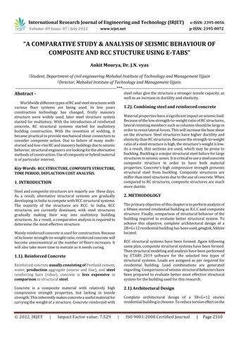
Theprimaryobjectiveofthischapteristoperformanalysisof afifteenstoriedresidentialbuildingasR.C.Candcomposite structure.Finally,comparisonofstructuralbehaviorofthe building required to evaluate better structural system. To achieve this objective, complete architectural design of a 2B+G+12residentialbuildinghasbeenused,gengtok,Sikkim located.
RCCstructuralsystemshavebeenformed.Againfollowing sameplan,compositestructuralsystemshavebeenformed. Thenstructuralmodelingandanalysishavebeenperformed by ETABS 2019 software for the selected two types of structural systems.Loadsare assigned as per required for residential building. Load combinations are generated regarding.Comparisonsofseismicstructuralbehaviorshave been prepared to evaluate better most effective structural systemforthebuildingusedforthisresearch.
Complete architectural design of a 3B+G+12 stories residentialbuildingischooses.Toreducetorsioneffectonthe
International Research Journal of Engineering and Technology (IRJET) e ISSN: 2395 0056
Volume: 09 Issue: 07 | July 2022 www.irjet.net p ISSN: 2395 0072
structuresymmetricfloorsystemsisused.Sincethestructure issymmetric.
RCstructuralsystemisformedwithbeamsupported12.5cm thick solidslab for the typical floor andalso 12.5 cmsolid slab for first basements and Ground floor. Structural is considered as intermediate moment resisting rigid frame Floor slab is assumed as rigid in plane which acts as diaphragmtotransferlateralloadhorizontallytoshearwalls and column. Design section for RC structureis shown in Appendix
For the same floor plan as shown in plan, composite structureismodeledasthesamewayastheR.C.Cstructure except Composite sections are used for column. System is usedas.Designsectionforcompositestructureisshown.
Figure
Butinthisanalysisweusedsolidslabforarigiddiaphragm. But for composite structure reinforced concrete slab on corrugatedsteeldeckisformedascompositeisused.
Deadload selfweightofthestructure. Liveload asperIS 875part 2. LateralloadcalculationasperIS1893 2016
This section deals with; structural modeling, assigning memberproperties,assigningbasicloads,generationofload combinations and structural analysis of the two types of structuresfortheintendedresearchwork
The Following specifications of materials are used in designing of RCC and composite members and joints: Hot rolledsectionusedforcompositestructure.Grade500steel with Fy = 500MPa and Fu = 545 MPa is used.). Concrete strengthusedism30forcolumnandbeams.Forslabm30is used.
The objective of this study is to compare and discuss the design and construction of a single building using various data sources such as structural modeling, designing load calculation, and RCC and composite types of structural system.
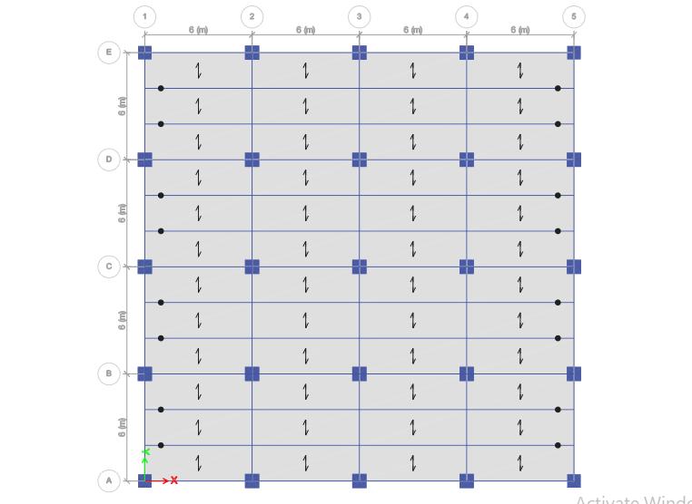
Figure 2.2 3D View of structural framing system
The3Dbuildingmodelisthenanalyzedusingthesoftware ETABS2019.Thedifferentparameterssuchasbaseshear, andtimeperiodarethenstudiedtodeterminethemodel's performance.
2022, IRJET | Impact Factor value: 7.529 | ISO 9001:2008 Certified Journal | Page2311
International Research Journal of Engineering and Technology (IRJET) e ISSN: 2395 0056
Volume: 09 Issue: 07 | July 2022 www.irjet.net p ISSN: 2395 0072
Everybuildinghasitsownnaturalfrequency,whichlimitsits resistance to external and internal effects, such as earthquakes and wind. The smallest natural frequency is referred to as the Fundamental Mode, while the largest naturalperiodistheFundamentalNaturalPeriod.
Thetimeperiodistheperiodoftimerequiredforanobject to complete one full cycle of motion. It is one of the most important facets in determining out how a structure will behavetogroundshaking.Weused20modesintheanalysis, and each mode had its own time period. We see the time periodsofthethreestructures
Table 3.1 Time Period for all modes
Time Period(sec)
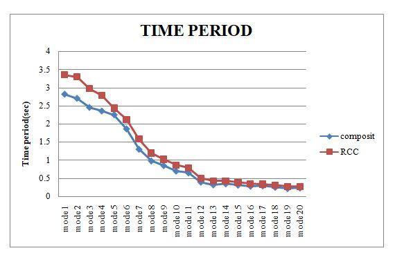
Mode Composite RCC
Mode 1 2.814 3.35 Mode 2 1.731 2.103 Mode 3 2.45 2.976
Mode 4 1.18 1.361 Mode 5 1.1 1.318 Mode 6 1.23 1.453
Mode 7 0.65 0.803
Mode 8 0.62 0.78
Mode 9 0.59 0.722
Mode 10 0.442 0.551
Mode11 0.45 0.539
Mode12 0.396 0.499
Mode13 0.321 0.427 Mode14 0.35 0.417 Mode15 0.3135 0.385 Mode16 0.286 0.341 Mode17 0.294 0.335 Mode18 0.256 0.31 Mode19 0.2198 0.273
Displacements, the extent to which a structural element moves or bends under pressure is the main serviceability concerninthestructures.
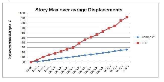
Fig. 3.1 model Time period of structural system
Table 4 2 X direction deflection
X Direction Defection (mm)
Location Composite RCC Base 0 0
Basement 3 0.907 4.65 Basement 2 2.58 10.202 Basement 1 4.39 14.748 Story1 6.09 18.201 Story2 7.7 21.834 Story3 9.31 26.405 Story4 10.84 29.387 Story5 12.43 38.696 Story6 13.955 45.65 Story7 15.379 50.98 Story8 17.137 56.287 Story9 18.733 62.74 Story10 20.2 69.55 Story11 22.42 73.89 Story12 24.21 84.46 Roof top 25.425 91.76
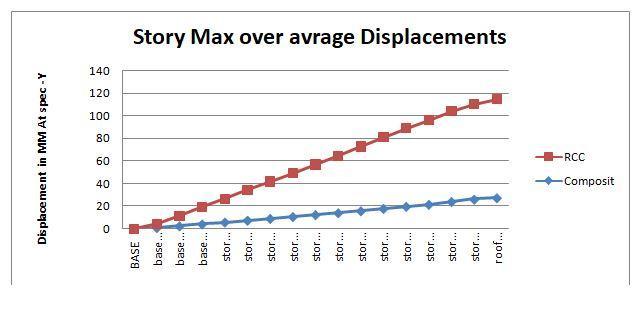
Y Direction Deflection
Y Direction Deflection (mm)
Location Composite RCC Base 0 0
Basement 3 0.808 3.497 Basement 2 2.306 9.22 Basement 1 4.027 15.07
Story1 5.72 20.81 Story2 7.342 26.89 Story3 8.97 32.74 Story4 10.6 38.36
Story5 12.35 44.46 Story6 14.03 50.44 Story7 15.71 56.94 Story8 17.78 63.28
International Research Journal of Engineering and Technology (IRJET) e ISSN: 2395 0056
Story9 19.68 69.19 Story10 21.46 74.6 Story11 24 79.86 Story12 26.02 84.05 Roof Top 27.32 86.98 Fig. 3.3 comparison Y direction deflections
Story Stiffness in the X Direction Story Composite RC
BASE 0 0 basement1 71095.817 309324.33 basement2 79393.376 335360.96 basement3 84642.812 335075.72 story1 155201.13 351616.79 story2 169086.06 354913.52 story3 174920.87 357946.44 story4 240628.36 362220.46 story5 247454.86 379805.97 story6 255303.35 384167.24 story7 284752.06 398980.82 story8 287796.41 404263.58 story9 305251.99 411720.2 story10 306602.57 437701.01 story11 305853.92 478533.86 story12 345955.08 604251 rooftop 652527.59 1350433.7
Story Stiffness in the Y-Direction Story Composite RC
BASE 70848.175 61508.805
basement1 85644.776 73039.302 basement2 102454.47 77101.674 basement3 129838.32 90364.595 story1 142037.11 93706.749 story2 146645.95 96707.821 story3 201807.98 102483.98
story4 224263.74 121386.13 story5 233372.68 128869.58 story6 266834.29 152046.45 story7 281636.04 158491.52 story8 301745.27 164799.55 story9 307293.75 186854.04 story10 322231.64 193283.88 story11 390675.39 204746.58 story12 741943.79 338733.74 rooftop 652527.59 1350433.7
When using RCC structure the fundamental period (First mode time period) of RCC structure is 16% higher comparetoCompositestructure.
The maximum roof displacement for the X direction for RCC structure 26% higher compare to Composite structure. The maximum roof displacement for the Y directionforRCCstructureis31%higherthancompareto Compositestructure.
The maximum Story stiffness for the X direction for RCC structure is 11% lower than compare to composite structure.
WhenusingRCstructurethefundamentalperiod(First modetimeperiod)ofCompositestructureisabout16% lowerthanRCCstructure.
ThemaximumroofdisplacementfortheX directionfor compositestructureis26%lowerthancomparetoRCC structure. The maximumRoofdisplacementfortheY direction for composite structure is 31% lower than RCCstructure.
The maximum Story stiffness for the X direction for compositestructureis11%higherthancomparetoRC C structure. The maximum Story stiffness for the Y direction for composite structure is 19%higher than thatofRCCstructure.
[1] Kumawat. M “Analysis and Design of Multistory Building Using Composite Structure”, International Journal of Structural and Civil Engineering Research, ISSN2319 6009,Vol.3,No.2(May 2014).
Volume: 09 Issue: 07 | July 2022 www.irjet.net p ISSN: 2395 0072 © 2022, IRJET | Impact Factor value: 7.529 | ISO 9001:2008 Certified Journal | Page2313
International Research Journal of Engineering and Technology (IRJET) e ISSN: 2395 0056 Volume: 09 Issue: 07 | July 2022 www.irjet.net p ISSN: 2395 0072
[2] S.S Charantimath “Comparative Study on Structural ParameterofR.C.C.andCompositeBuilding”,Civiland EnvironmentalResearchISSN2224 5790,Vol.6,No.6, (2014))
[3] Jirage D. “Comparative Study of RCC and Composite Multi storied Building”, International Journal of Scientific Engineering and Applied Science (USEAS), Vol.1,Issue:6(Sep.2015)
[4] Prof. Swapnail B “ComparativeAnalysisofMultistoried RCCandCompositeBuildingduetoMassIrregularity” International Research Journal of Engineering And Technology,Vol.02,Issue:04(July 2015).
2022, IRJET | Impact Factor value: 7.529 | ISO 9001:2008 Certified Journal