International Research Journal of Engineering and Technology (IRJET)
e-ISSN: 2395-0056
Volume: 09 Issue: 07 | July 2022
p-ISSN: 2395-0072
www.irjet.net
Deployment of Debug and Trace for features in RISC-V Core Sharad1, Dr. Kiran V2 1Student,
RV College of Engineering, Karnataka India Professor, RV College of Engineering, Karnataka India ---------------------------------------------------------------------***--------------------------------------------------------------------2Associate
Abstract - Modern technology complexity of SOC designs
debugging and tracing in the "RISC V core" is crucial for validating new features because design flaws cost the firm time, effort, and resources.
makes it challenging to create a bug-free design. Therefore, the chip design pipeline includes a number of procedures to find faults both early on and later on. By locating the problems in the system and localising them, verification and validation both check if the design adheres to the specification, but at separate points in the design cycle. Verification is a pre-silicon process that involves modelling the functioning of the design. The method of proving that an RTL design is functionally accurate with regard to the design standards is known as functional verification. Functional verification makes an effort to determine whether the suggested design is performing as expected. The majority of the time and energy required for most significant electrical system design projects is spent on this complicated endeavour. It is essential that the design be functionally tested and that any possible bugs be found early. This paper discuss about verification done using trace method of debugging in RISC V core.
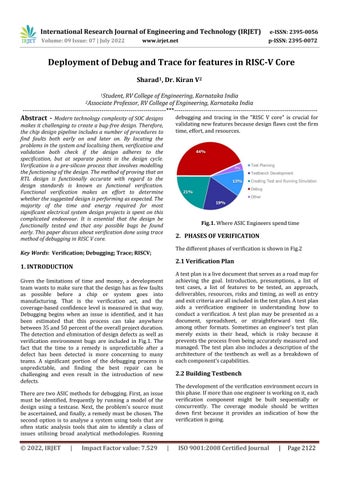
Fig.1. Where ASIC Engineers spend time
2. PHASES OF VERIFICATION The different phases of verification is shown in Fig.2
Key Words: Verification; Debugging; Trace; RISCV;
2.1 Verification Plan
1. INTRODUCTION
A test plan is a live document that serves as a road map for achieving the goal. Introduction, presumptions, a list of test cases, a list of features to be tested, an approach, deliverables, resources, risks and timing, as well as entry and exit criteria are all included in the test plan. A test plan aids a verification engineer in understanding how to conduct a verification. A test plan may be presented as a document, spreadsheet, or straightforward text file, among other formats. Sometimes an engineer's test plan merely exists in their head, which is risky because it prevents the process from being accurately measured and managed. The test plan also includes a description of the architecture of the testbench as well as a breakdown of each component's capabilities.
Given the limitations of time and money, a development team wants to make sure that the design has as few faults as possible before a chip or system goes into manufacturing. That is the verification act, and the coverage-based confidence level is measured in that way. Debugging begins when an issue is identified, and it has been estimated that this process can take anywhere between 35 and 50 percent of the overall project duration. The detection and elimination of design defects as well as verification environment bugs are included in Fig.1. The fact that the time to a remedy is unpredictable after a defect has been detected is more concerning to many teams. A significant portion of the debugging process is unpredictable, and finding the best repair can be challenging and even result in the introduction of new defects.
2.2 Building Testbench The development of the verification environment occurs in this phase. If more than one engineer is working on it, each verification component might be built sequentially or concurrently. The coverage module should be written down first because it provides an indication of how the verification is going.
There are two ASIC methods for debugging. First, an issue must be identified, frequently by running a model of the design using a testcase. Next, the problem's source must be ascertained, and finally, a remedy must be chosen. The second option is to analyse a system using tools that are often static analysis tools that aim to identify a class of issues utilising broad analytical methodologies. Running
© 2022, IRJET
|
Impact Factor value: 7.529
|
ISO 9001:2008 Certified Journal
|
Page 2122