International Research Journal of Engineering and Technology (IRJET) e ISSN: 2395 0056

Volume: 09 Issue: 07 | July 2022 www.irjet.net p ISSN: 2395 0072
International Research Journal of Engineering and Technology (IRJET) e ISSN: 2395 0056
Volume: 09 Issue: 07 | July 2022 www.irjet.net p ISSN: 2395 0072
Chigullapalli Rahul1, Polu Sankeerth2 , Kalimera Uttej3, Kukkada Arun4 , K.Raja sekhar5
1 Student, Mechanical department, Sreyas Institute of Engineering and Technology, Telangana, India. 2,3,4 Students, Mechanical department, Sreyas Institute of Engineering and Technology, Telangana, India. 5 Associate Professor, Dept. of Mechanical Engineering, Sreyas Institute of Engineering and Technology. ***
Abstract In the present scenario,thelathemachineplaysa vital role in the engineering division of the manufacturing industry. While the manual lathe machines are economical, their accuracy and efficiency are not up to the mark. Contrarily, CNC machines deliver the desired accuracy and efficiency but demand a significant investment in capital. In order to address this issue, a smart lathe machineapproachto the traditional lathe machine hasbeendeveloped. Itmakesuse of sensors and actuators that can be managed by the Arduino UNO microcontroller and NodeMCU Therefore, switching from manual to smart lathe machines can significantly improve accuracy and efficiency while also controlling investment costs, giving the manufacturing industry a much needed boost. This configuration enables a machinist to inspect the workpiece's dimensions without removing it, as well as display the chuck's speed and other features. Industry 4.0 inspired digital technologies are driving a new business environment that is increasinglysustainable.Purchasingnew generation machinery makes it possible to take advantage of the many advantages of digitalization, including increased productivity, flexibility, efficiency, and quality, reduced resource consumption, and improved worker safety. By combining mechanical, electronic, and software technologies, the traditional lathe machine is transformed into a smart lathe machine. For the sake of novelty, accuracy, and time decreasing, a conventional lathe machine has been converted into a smart lathe machine by retrofitting to show readings of the dimensions of the workpiece, speed of the chuck, motor temperature, and distance from the headstocktothetailstock, and it can be accessed by the RFID tags only.
Key Words: Manufacturing,Industrialrevolution,IoT,Lead time,Accuracy,Retrofitting,Remodification.
Alathemachineusesacuttingtooltoremovematerialfrom theworkpiece'ssurface.Theworkpieceisheldinthechuck, andthetoolfeedsmaterialontotheworkpiecetoperform various operations like cutting, drilling, knurling, deformation, turning, and facing. It is one of the most adaptable and frequently used machines in workplaces, workshops,andeducationalinstitutions.
Retrofitting describes the situation in which modern featuresortechnologyareaddedtooldersystemstoupdate their components and enhance their functionality. This
definitioncoversnearlyalloftheinformationabouttheterm "retrofitting" as it also refers to the integration of new featuresortechnologyintooldersystems.Whenretrofitting is used in reference to traditional lathes, it refers to modernizingthelatheandenhancingitsproductivity.
Repairingorreplacingmechanicalpartstotheoriginal,as newfactoryspecificationsisknownasremanufacturing. The machine will be completely disassembled, cleaned, examined,repaired,andpainted. Updateswillbemadetoall electrical,hydraulic,andpneumaticsystems.Toadaptthe machineforadifferentuse,itmayalsobemodifiedorgiven mechanicalaccessories.Remanufacturingwillalmostalways happenattheremanufacturer'slocation.Themaingoalof incorporating a smart lathe machine into an existing conventional lathe machine is to enhance it with features suchasnon contactworkpiecedimensionmeasurementand condition monitoring of the electrical components of the lathe.[1]
Thegoalsofretrofittingconsistof
implementingnewmanufacturingtechniques.
minimizingmachineidling.
greaterspeeds.
decreasedtoolcosts
friendlyservice.
increasedoutputandimprovedmachinecontrol.
significantlygreaterrepeatability
toreduceleadtime,
veryquickmachiningcycles.
highprecision.
Retrofitting should be much less expensive overall than buyinganewsystem.
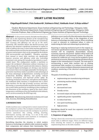
Thefig1showstheconversionofaconventionallatheintoa smart lathe in different stages. There are different stages, from selecting the sensors to programming them and implementingthemonthelathemachine.
International Research Journal of Engineering and Technology (IRJET) e ISSN: 2395 0056
Volume: 09 Issue: 07 | July 2022 www.irjet.net p ISSN: 2395 0072

Fig 2: Sensorconnectivitytomicrocontrollers
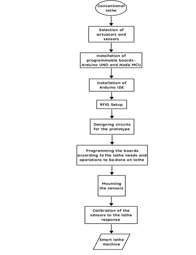
Thefig2,blockdiagram,explainsthedifferentsensorsand actuatorsconnectedtotheprogrammableboardssuchasthe Arduino UNO and NodeMCU. The actuators still require a 12Vpowersourceeventhoughalltheelectronicpartsare connected to 5V. The microcontroller gathers the sensor dataandusestheI2Ccommunicationprotocoltosenditto theLCD.AnInternetofThings(IoT)devicecalledNodeMCU cansenddatainformatsthatarereadablebyhumansover Wi Fi.[2]
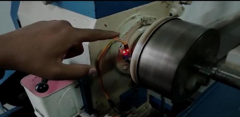
Thefig3representstheconnectionsofsensors,actuators, relays, and other electronic components connected to the ArduinoandNodemcu.
Arduinoisanopen sourceplatformforprototypingthatis built on user friendly hardware and software. Arduino boardshavetheabilitytoreadinputs,suchaslightfroma sensor or pressurefroma fingerona button,andconvert themintooutputs,suchasturningonamotororanLED.By sendingasetofinstructionstothemicrocontroller,theuser caninstructtheboardwhattodo.Theusershoulddothisby
International Research Journal of Engineering and Technology (IRJET) e ISSN: 2395 0056
Volume: 09 Issue: 07 | July 2022 www.irjet.net p ISSN: 2395 0072
utilizing the Arduino Software (IDE), which is based on Processing, and the Wiring based Arduino Programming Language(basedonWiring).BasedontheATmega328P,the Unoisamicrocontrollerboard.
Fig 5: ArduinoUNO[5]
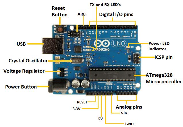
TheATmega328Pmicrocontrolleristhefoundationofthe ArduinoUNO.Comparativelyspeaking,itissimplertouse than other boards like the Arduino Mega board, etc. The boardismadeupofshields,othercircuits,anddigitaland analog Input/Output (I/O) pins. The Arduino UNO has 14 digitalpins,aUSBport,apowerjack,andanICSP(In Circuit Serial Programming) header, in addition to 6 analog pin inputs.AnIDE,orintegrateddevelopmentenvironment,is the platform on which it is programmed. Both online and offlineplatformsarecompatiblewithit.TheFTDIUSB to serial driver chip is absent from the Uno, setting it apart fromallpreviousboards.Instead,itusesanAtmega16U2 (Atmega8U2uptoversionR2)thathasbeenconfiguredasa USB to serial converter. The USB ports on your computer areshieldedfromshortsandovercurrentbytheresettable poly fuseontheUno.
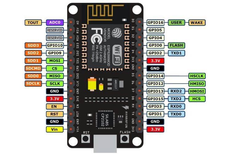
A low cost System on a Chip (SoC) called the ESP8266 serves as the foundation of the NodeMCU (Node Microcontroller Unit), an open source environment for developing both software and hardware. The Espressif Systems designed and produced ESP8266 has all of the essential components of a computer, including CPU, RAM, networking (Wi Fi), and even a contemporary operating systemandSDK.Becauseofthis,itisagreatoptionforall typesofInternetofThings(IoT)projects.
Fig 6: NodeMCU [6]
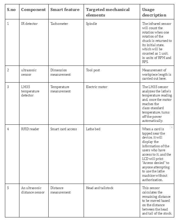
Thebelowfigure7showslistofIoTfeaturestobegivenfora conventionallathemachinetoupgradeitintoasmartlathe machine
International Research Journal of Engineering and Technology (IRJET) e ISSN: 2395 0056
Volume: 09 Issue: 07 | July 2022 www.irjet.net p ISSN: 2395 0072
Step 7) In the case of Nodemcu, the output of the written code is checked on the serial monitor for debugging purposes.
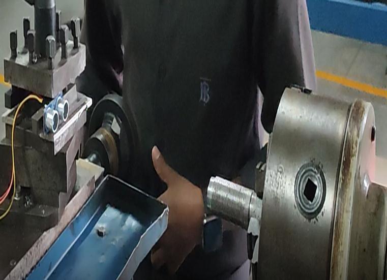
Step8)Meanwhile,theworkpieceismountedonthechuck ofthesmartlatheasshowninFigure3.
Step9)Now,theArduinoreadstheprogramand,basedon theinputofthelathe,showstheoutputontheLCDdisplayto themachinist.
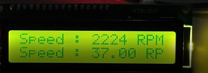
Step10) When the procedure is complete, adjusting the potentiometertotheleftandrightwillshowthevaluesof additional parameters, such as spindle speed, motor temperature,etc.[3][4]
Fig -7: Smartfeaturesgiventomechanicalelements
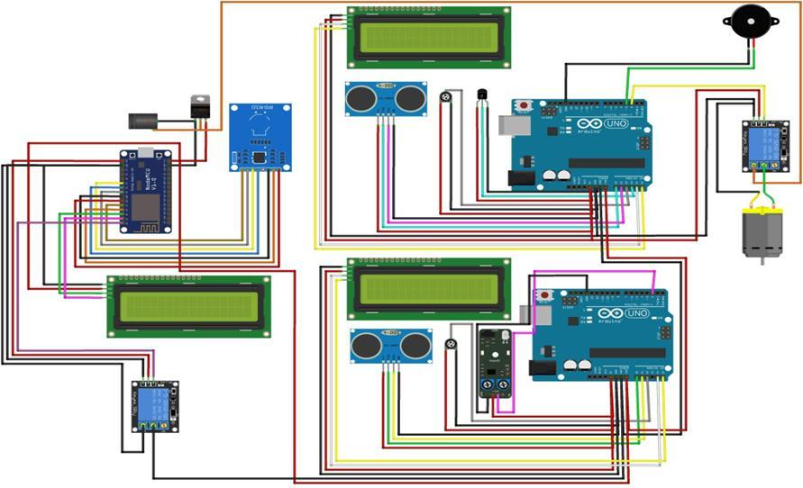
Step1)The“ArduinoSoftwareIDE”isinitializedasshownin Figure4.
Step 2) Based on the input parameters, the program is writtenaccordingly.
Step3)Writtencodemusthavetherequirementsofallthe sensorsthatshouldalsobementionedinthevoidsetup,and sensorinformationandconnectionsareinitializedabovethe voidsetup.
Step4)Theactualworkingmodelshouldbewritteninavoid loopsoastorepeattheprocessinaloopmanner.
Step5) Nowthecodingiscompiled.sothatitensuresthe sketchisfreetoupload.
Step6)ThesecodesaretransmittedtotheArduinoboardby meansofaUSBcable.
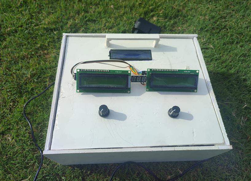
3. Working model
Fig 9: Workingmodelofsmartlatheprototype
International Research Journal of Engineering and Technology (IRJET) e ISSN: 2395 0056
Volume: 09 Issue: 07 | July 2022 www.irjet.net p ISSN: 2395 0072
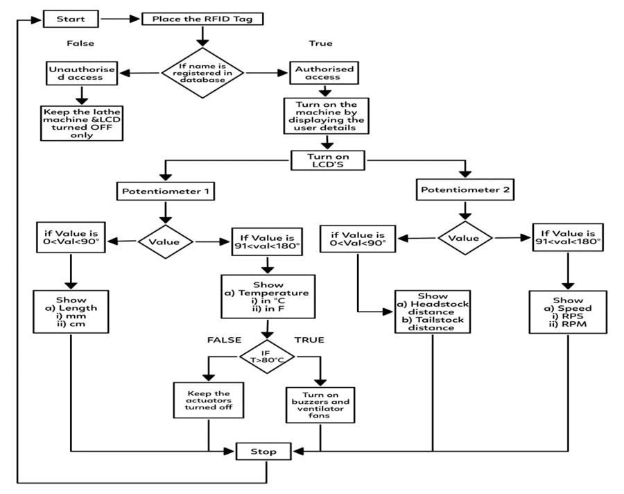
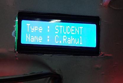
Theaboveactivitydiagram(fig9)showstheworkingmodel ofthesmartlathemachine.Firstly,it will beturnedonby RFIDaccess.Ifthereisnoaccess,thenthelathewillnotturn on.Thisisforsecurityreasonsandalsotoavoidunwanted peoplefromoperatingthelathe.
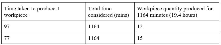
Whenusingthelathemachinetoperformtaskslikecutting, drilling, facing, knurling, and turning, an aluminum workpiece is taken into account. When comparing a conventionallatheandasmartlathe,thetimerequiredfor theseoperationsisnotedasthetimedifference. Thesmart lathemachinesaves20minutesasshownintable1.when compared to a conventional lathe when performing all 5 operations, which takes 97 minutes as opposed to 77 minutes.
Thisprocesstookthetraditionallathe1164minutes(19.4 hours)toproduce12pieces.Keepingthesametimeforthe smartlathe,itproduced15pieces.whichisalmost3extra piecesatthesametimeasshownintable2.
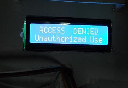
Fig 10: Accessauthorized
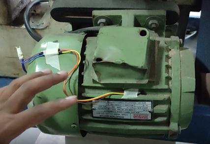
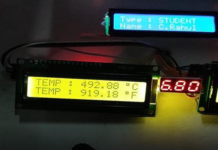
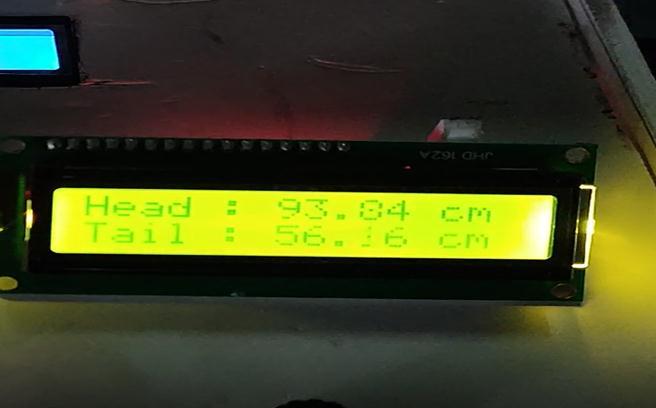
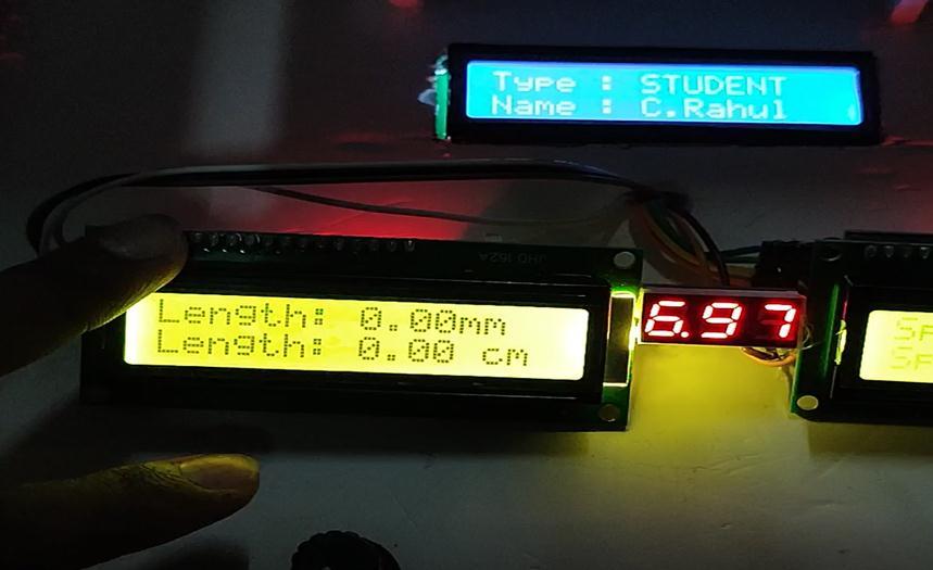
Due to inadequate training, if someone uses the lathe machine without authorization, they run the risk of damagingitorbecominginjured.Whentheusergainsaccess tothemachine,theLCDwillturnonanddisplaydatafrom various sensors, including temperature, spindle speed, workpiecelength,anddistancesbetweentheheadstockand tailstock. The lathe machine continues to perform all the tasks while it is in use and becomes heated. When the machine's motor reaches a temperature of more than 80 degrees Celsius, it automatically shuts off and sounds a buzzer to let the user know how things are going. The ventilatorsarealsoactivatedatthattime.
Time saved by the smart lathe in comparison with conventionallathe.
Table -2: Workpiecequantityafter19.4hours
Table 1: Leadtimewithrespecttolatheoperations
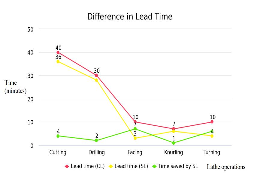
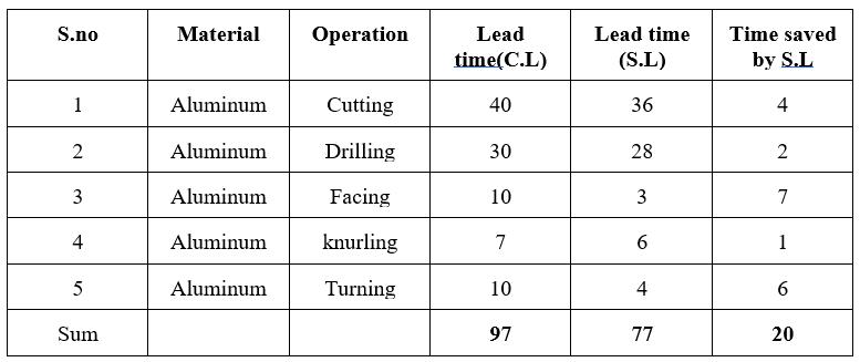
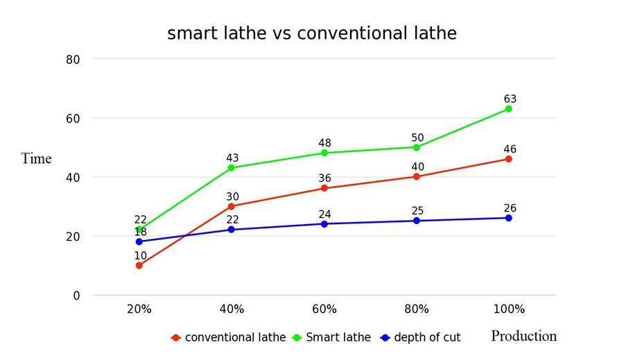
Thegreenlineinthefig12showshowmuchtimethesmart lathemachinesaveswhenperformingthesameoperations compared to the conventional lathe machine. The smart lathehassaved20minutesinthepreparationofaworkpiece basedonfiveoperations.
Specificationsoftheworkpiece
Specimen
: Aluminumrod
Totallength : 400mm
Initialdiameter : 200mm
International Research Journal of Engineering and Technology (IRJET) e ISSN: 2395 0056
Volume: 09 Issue: 07 | July 2022 www.irjet.net p ISSN: 2395 0072
Finaldiameter : 150mm
Removeddiameter : 50mm
Depthofcut : 25mm
Cuttingspeed : 251.2m/min
RPM : 500
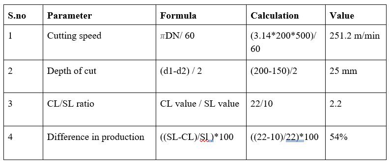
Theabovetable3showsthecalculationsoftheworkpiece beforeandafterthe machining.A25mmdepth ofcutwas given to the specimen, and there was a huge difference in productionquantityfromtwolathes.
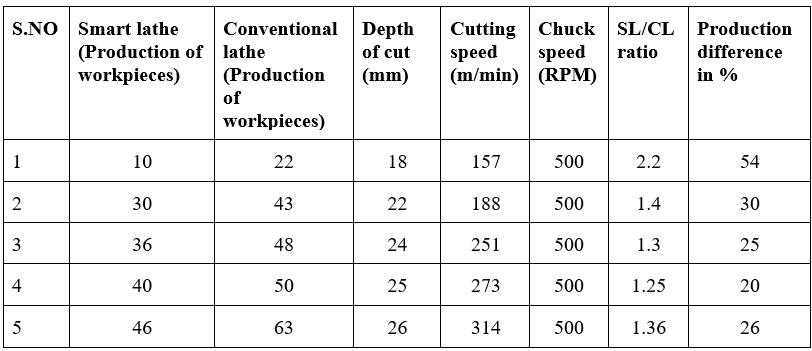
Thetable4illustratestheproductiondifferencesbetween conventional and smart lathe machines for machining aluminum workpieces (quantity). For a smart lathe and a traditional lathe, respectively, the maximum number of workpiecesthatcanbeproducedat100%is63and46.The time required by traditional machines to place the workpiece in the chuck, remove it again, and check the workpiece'sdimensionswillbesignificantlygreater.Thisis wherethetwomachinesareverydifferentfromoneanother. The workpiece is once more placed into the chuck for additional machining if the employee feels the desired dimensions are not being achieved. However, there is no needtotaketheworkpiece outofthechuckwhenusinga smartlathe. Savingtimeisachievedbythesensor'sabilityto display values without making contact. Workers will eventually have the opportunity to machine another workpieceastimepermits,whichwillincreaseproduction.
Lowlaborcostsandhigh qualityoutputarebenefitsofusing a smart lathe machine. The smart lathe machine allows a machinist to control the temperature of the machine and turnitoffwhileheisaway.Thecurrentworkisanticipated tobehelpfulforthemanufacturingindustryaswellasthe research community with regard to cost basis. Through a series of design changes and the use of a retrofitting technique,a conventional lathemachinecanbeconverted into a smart lathe machine. As a result, NodeMCU and Arduinoweresuccessfulincreatingthedesignforthesmart lathe. which, thanks to the collaboration of hardware (ArduinoUNO)andsoftware(ArduinoIDE),hasledtothe development of a semi automated approach to the traditionallathemachine.Byaddingafewnewfeaturesto theexistinglathe,thenewlycreatedArduinolathe'ssetup cost is increased; however, when compared to the fully automated/CNC machine, the setup cost is significantly lower. The repeatability and dimensional stability of the manufacturedpartareachievedduetotherelativelyhigh accuracyofthejobmanufacturedinasemi automatedlathe.
[1] Parmar, Prakash & Mehta, Nirajkumar. (2014). Investigation on Automation of Lathe Machine. International Journal of Emerging Technology and AdvancedEngineering.4.524.
[2] Abd Alrazzaq,Mohamed&Ahmed,Mahmoud&Younes, Mohammad. (2019). A computer numerical control (CNC) multi pass spinning solution to a center lathe retrofit.SNAppliedSciences.1.10.1007/s42452 018 0007 x.
[3] Sakthi,S&Niresh,J&Vignesh,K&Raj,Goutom.(2018). Development of Semi Automatic Lathe by using Intelligent SoftComputingTechnique.IOPConference Series:MaterialsScienceandEngineering.324.012053. 10.1088/1757 899X/324/1/012053.
[4] Ilari, Serena & Carlo, Fabio & Ciarapica, Filippo Emanuele&Bevilacqua,Maurizio.(2021).MachineTool Transition from Industry 3.0 to 4.0: A Comparison betweenOldMachineRetrofittingandthePurchaseof
International Research Journal of Engineering and Technology (IRJET) e ISSN: 2395 0056
NewMachinesfromaTripleBottomLinePerspective. Sustainability.13.10441.10.3390/su131810441. [5] ArduinoUNO JavaTpoint
[6] NodeMCU ESP8266 Pinout, Specifications, Features & Datasheet(components101.com)
Volume: 09 Issue: 07 | July 2022 www.irjet.net p ISSN: 2395 0072 © 2022, IRJET | Impact Factor value: 7.529 | ISO 9001:2008 Certified Journal |