International Research Journal of Engineering and Technology (IRJET) e ISSN: 2395 0056

Volume: 09 Issue: 07 | July 2022 www.irjet.net p ISSN: 2395 0072

International Research Journal of Engineering and Technology (IRJET) e ISSN: 2395 0056
Volume: 09 Issue: 07 | July 2022 www.irjet.net p ISSN: 2395 0072
Delhi Technological University, New Delhi, India ***
Abstract - An internal combustionenginehasaconnectingrod as a major component. It acts as a transmission mechanism to convert the reciprocating piston motion into rotary motion by transmitting the push and pull from the piston pin to the crank pin. A 4 stroke petrol engine of a specified model, with a market available connecting rod, is the object of the current study. This investigation uses solid modeling software called PRO/E(Creo Parametric). The modeled connecting rod is imported to an analysis program called ANSYS. Analysis software ANSYS is used to determine von mises stresses, equivalent and shear strains, shear stresses, and total deformation for given loading conditions. The analysis focuses on the analysis of three materials Aluminum Alloy(Al 6061), Structural Steel, and Gray Cast Iron. A 6061 aluminum alloy is part of the 6xxx aluminum alloy family, which consists primarily of magnesium and silicon alloys. Aluminum 6061 has a nominal composition of 97.9% Al, 0.6% Si, 1.0% Mg, 0.2% Cr, and 0.28% Cu. A connecting rod is designed based on the results of software that compares three materials.
Key Words: ConnectingRod,PRO/E(CreoParametric),ANSYS, FEA(FiniteElementAnalysis)
The connecting rod in a combustion engine is a major component. By connecting the piston to the crankshaft, it transfers power from the piston to the crankshaft and the transmission.Aconnectingrodcanbemadeofvarioustypesof materialsandproducedindifferentways.Steelandaluminum arethetwomostcommonmaterialsusedinconnectingrods. Amongthemostcommonmanufacturingprocessesarecasting, forging, and powdered metallurgy. In internal combustion engines, connecting rods constitute a large portion of the production volume. Besides connecting the piston with the crankshaft, this component is responsible for transmitting powerfromthepistontothecrankshaft.Connecting rodsare madefromvarioustypesofmaterialsandaremanufacturedin differentways.
Asaresultoftheoperation,theconnectingrodissubjectedto majoraxialandbendingstresses Asaresultofthecylindergas pressure(onlycompressive)andtheinertiaforcearisingfrom reciprocating action (both tensile and compressive), axial stressesareproduced,whilebendingstressesarecreateddue tocentrifugalforce.
Connecting rodhasalongshank,asmallend,andalargeend. Theshank'scross sectioncanberectangular,circular,tubular, I section, or H section. In general, circular sections are preferred for low speed engines, whereas I sections are preferred for high speed engines. Casting, forging, and powdered metallurgy are the most common types of manufacturingprocesses.Acomplexstateofloadingisapplied totheconnectingrod.Itissubjectedtohighcyclicloadsofthe orderof10^8to10^9cycles,rangingfromhighcompressive loads caused by combustion to high tensile loads caused by inertia.Asaresult,thedurabilityofthiscomponentiscritical. Because of these factors, the connecting rod has been the subject of research in a variety of areas, including manufacturingtechnology,materials,andperformance.
This work aims at analyzing and comparing connecting rods made of aluminum alloy(Al 6061), structural steel, and gray castiron.TheconnectingrodmodelwascreatedinPro E(Creo parametric 8.0) and imported into ANSYS 2022 R1 for static analysis.Basedontheanalysis,anassessmentismadebetween an aluminum alloy and a steel connecting rod regarding Equivalent(Von Mises) stress, maximum shear stress, equivalentelasticstrain,andmaximumshearelasticstrain,as wellastotaldeformation.
PropertiesofMaterialsUsed
International Research Journal of Engineering and Technology (IRJET) e ISSN: 2395 0056
Volume: 09 Issue: 07 | July 2022 www.irjet.net p ISSN: 2395 0072
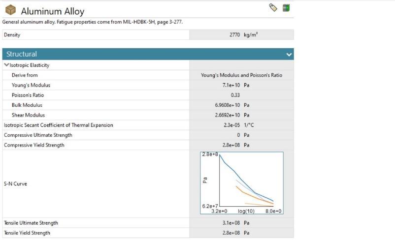
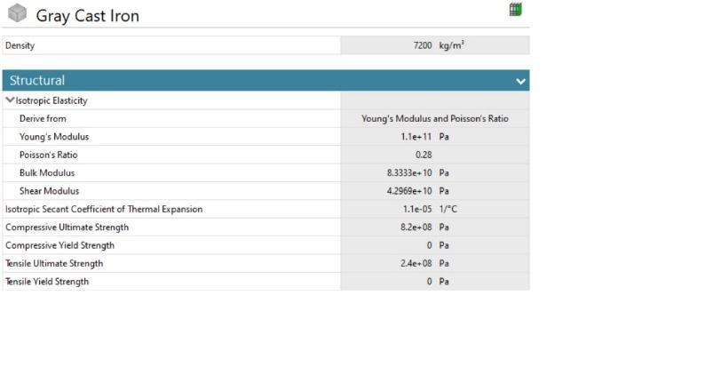
Table 1:PropertiesofAluminumAlloy(Al 6061)
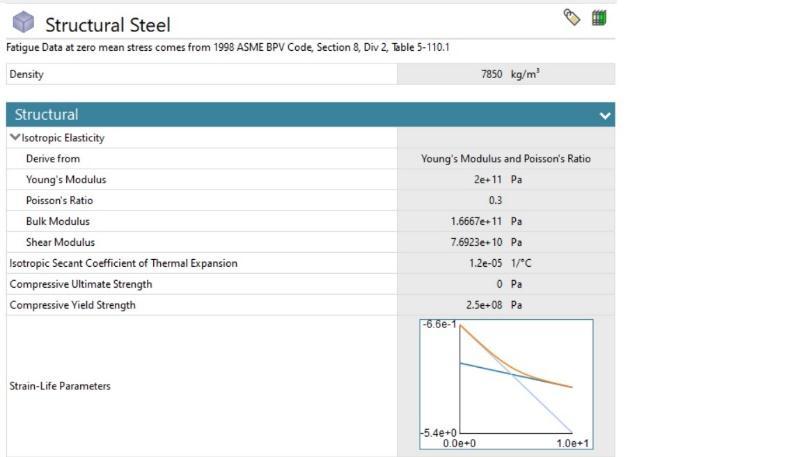
Table 3:PropertiesofStructuralSteel

Figure1illustratesasolidmodelofaconnectingrod.Modelling theconnectingrodfollowsthestepsoutlinedbelow.
a.Referenceplaneselection.
b. Setting of the dimensions in mm(dimensions have been takenfromreferencepapers).
c.Sketchingcircularentitiesatthesketcher.
d.Makingtheconnectingrodendsbyextrudingtheseentities.
e. Redefining the reference plane for the shank of the connectingrod.
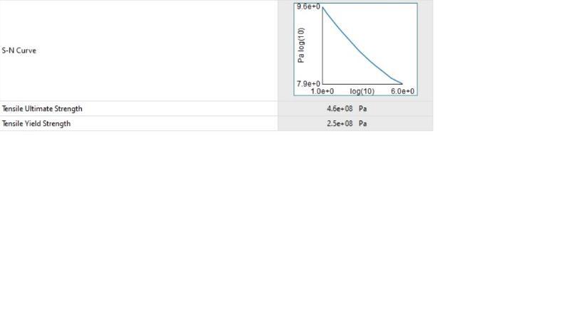
Table 2:PropertiesofGrayCastIron
f.Entitiesmadetobetangentialtobothends.
g.Symmetricalextrusionoftheentities.
h. Choosing the planes that will be used to make groove entities.
i.Theshankisgroovedandmirrored,resultingingrooveson bothsidesoftheshank.
Figure 1:ModelofConnectingRodinPTCCreoParametric
International Research Journal of Engineering and Technology (IRJET) e ISSN: 2395 0056
Volume: 09 Issue: 07 | July 2022 www.irjet.net p ISSN: 2395 0072

Theanalysisisperformedona3Dmodelofaconnectingrod usingANSYS2022R1workbench.Itisassumedthattheloading conditionsarestatic.Pressureloadsareappliedtobothendsof the piston and the fixed crank during the analysis. Finite elementanalysisiscarriedoutonstructuralsteelconnecting, castironaswellasonaluminumalloyconnectingrods.From theanalysistheequivalentstress(Von misesstress),equivalent strain, Max Shear stress, Max. Shear Strain and total deformationweredetermined.Aconnectingrodwitha fixed big end is shown in fig. 2 whereas the connecting rod with pressureatthesmallendisshowninfig.3.
Pressure applied:3.15 MPa
Figure 2:ConnectingRodwiththefixedbigend
Figure 5:EquivalentStressofCastIronConnectingrod

Figure 3:ConnectingRodwithpressureatthesmallend
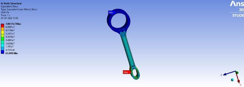
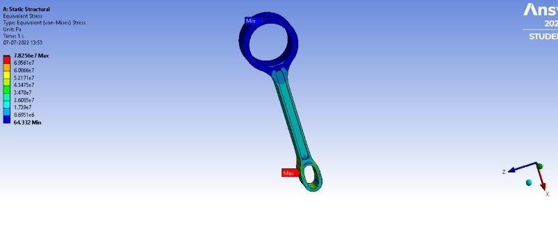
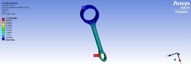
Fig.4,Fig.5,andFig.6showMinEquivalentstressas60.602Pa, 65.999Pa,and64.332andmaxequivalentstressas7.7714X 10^7 Pa, 7.18617 X 10^7 Pa, and 7.8256 X 10^7 Pa for a connecting rod made of Aluminum Alloy, Cast Iron and StructuralSteelrespectively.
Figure 6:EquivalentStressofStructuralSteelConnectingrod
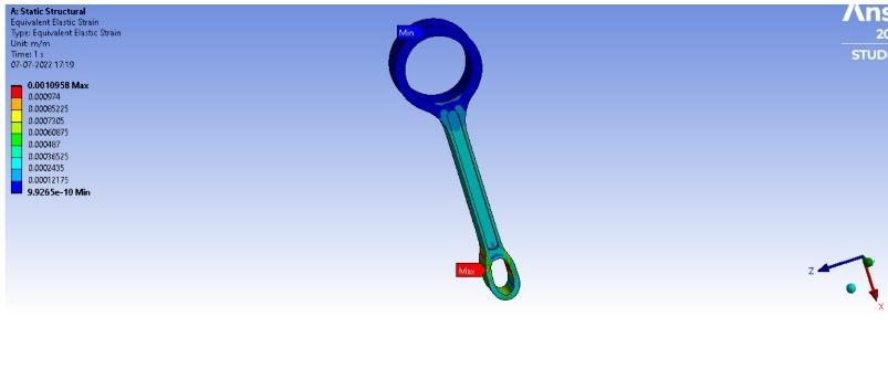
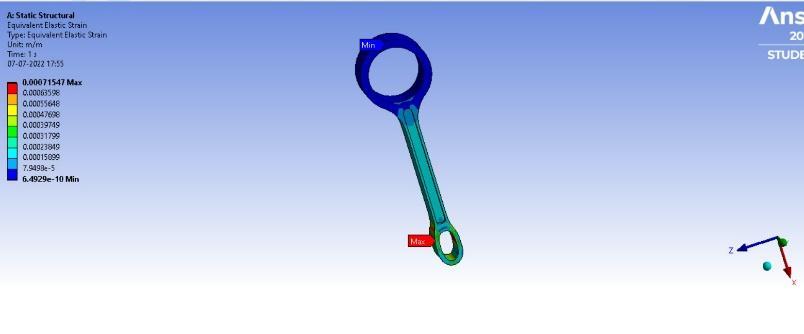
Fig.7,Fig.8,andFig.9showMax.Equivalentelasticstrainas 0.0010958,0.00071547,and0.00039171andMin.equivalent elasticstrainas9.9265X10^ 10,6.4929X10^ 10 and3.5605 X10^ 10foraconnectingrodmadeofAluminumAlloy,Cast IronandStructuralSteelrespectively.
Figure 4:EquivalentStressofAluminumalloyConnectingrod
Figure 7:EquivalentElasticStrainofAluminumalloy Connectingrod
Figure 8:EquivalentElasticStrainofCastIronConnecting rod
2022, IRJET | Impact Factor value: 7.529 | ISO 9001:2008 Certified Journal |
International Research Journal of Engineering and Technology (IRJET) e ISSN: 2395 0056
Volume: 09 Issue: 07 | July 2022 www.irjet.net p ISSN: 2395 0072
Fig. 7, Fig. 8, and Fig.9 show Max. Shear elastic strain as 0.0016099,0.00099443,and0.00055662andMin.Shearelastic strainas1.2281X10^ 9,8.2358X10^ 10,and4.5248X10^ 10 foraconnectingrodmadeofAluminumAlloy,CastIron,and StructuralSteelrespectively.
Figure 9:EquivalentElasticStrainofStructuralSteel Connectingrod
Fig.10,Fig.11,andFig.12showMin.Shearstressas32.781Pa, 35.388Pa,and34.806andMax.Shearstressas4.2971X10^7 Pa,4.2725X10^7Pa,and4.2817X10^7Paforaconnecting rod made of Aluminum Alloy, Cast Iron, and Structural Steel respectively.
Figure 10:MaximumShearStressofAluminumalloy Connectingrod
Figure 13:MaximumShearElasticStrainofAluminumAlloy Connectingrod
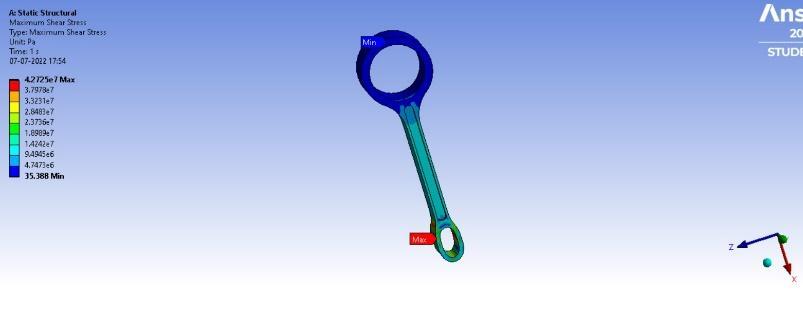
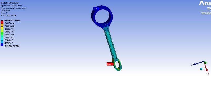
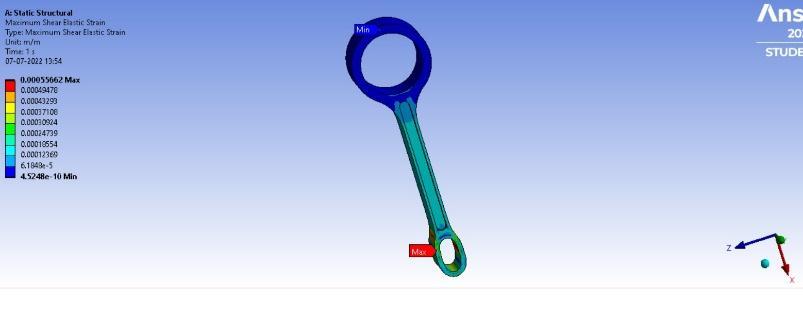
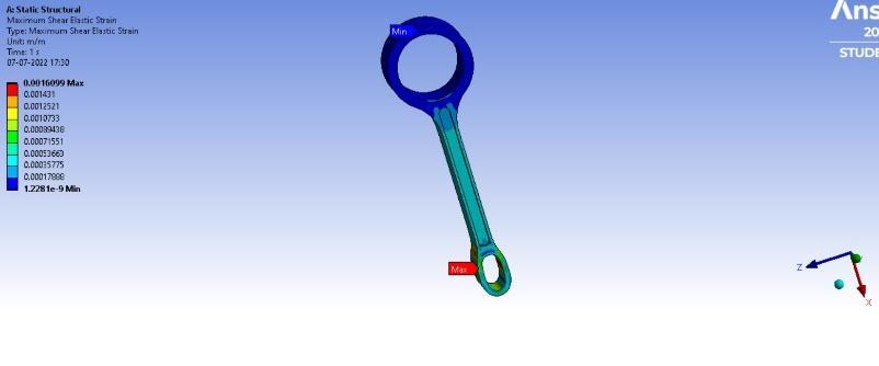
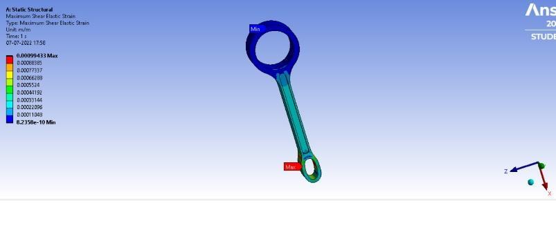
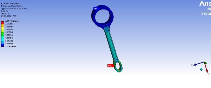
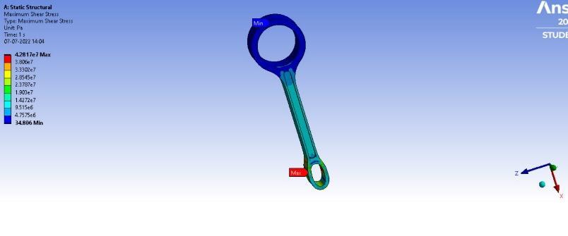
Figure 11:MaximumShearStressofCastIronConnecting rod
Figure 14:MaximumShearElasticStrainofCastIron Connectingrod
Figure 12:MaximumShearStressofStructuralSteel Connectingrod
Figure 15:MaximumShearElasticStrainofStructuralSteel Connectingrod
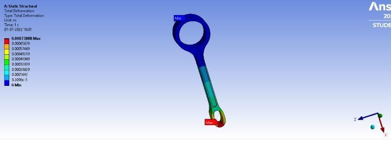
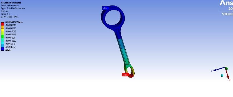
Fig. 16, Fig. 17, and Fig.18 show Max. Total Deformation as 0.00113159 m, 0.00073888 m, and 0.00040522 m and Min. TotalDeformationas0m,0m,and0mforaconnectingrod made of Aluminum Alloy, Cast Iron, and Structural Steel respectively.
International Research Journal of Engineering and Technology (IRJET) e ISSN: 2395 0056
Volume: 09 Issue: 07 | July 2022 www.irjet.net p ISSN: 2395 0072
Asaresultoftheultimatestrengthoftheconnecting rod,allofthematerialsaresafetouse.
The equivalent(Von Mises) stress, equivalent elastic strain, shear elastic strain, shear stress, and total deformation induced in structural steel for the currentinvestigationarelessthanthatincastiron, based on the comparisons obtained from the analysis.
Sincecastironisabrittlematerial,structuralsteelcan be used for manufacturing connecting rods with longdurability.
Compared to structural steel connecting rods, aluminumislighter.Consequently,whentherodis lighter, the piston pressure will be lower, and the fuelwillbeburnedless.
Byusinglightweightconnectingrods,wecanincrease fuel economy directly or indirectly. Weight is anotherfactorthataffectsthecostoftheconnecting rod. In comparison to heavy connecting rod materials, lighter connecting rods will be less expensive.
All connecting rods had the highest and lowest physical quantities at the piston and fixed ends, respectively.
Connecting rods made of Aluminum Alloy(Al 6061) exhibitedthehighestequivalentelasticstrain,shear elastic strain, shear stress, and total deformation followed by the ones made of Gray Cast Iron and StructuralSteelrespectively.
ConnectingRodmadeofGrayCastIronexhibitedthe highest Equivalent(Von Mises) Stress followed by the ones made of Structural steel and Aluminum Alloy(Al 6061)respectively.

Inthissector,muchhasbeendone,andmuchremainstobe done. Finite element analysis of static structural components is the only focus of this dissertation. It may therefore be necessary to conduct further research on dynamicloadingandoperatingconditionsoftheconnecting rod. Because of the oil holes provided on the connecting rods, CFD analysis can be used to improve the thermal behavioroftheconnectingrodsbyusingthermalanalysis. Inaddition,ExperimentalStressAnalysis(ESA)canbeused toevaluatetheperformanceofexistingmodelsbasedonthe behavior of connecting rods. Today, vibration analysis of mechanicalcomponentsiswidelydiscussedasitplaysan important role in the failure of these components. It is thereforepossibletoextendthestudytoincludeananalysis ofthevibrationoftheconnectingrods.
[1] Amir Hussain Idrisi, Sarbajit Roy, 2014, Modelling and Analysis of Aluminum Alloy Composite Connecting Rod, INTERNATIONALJOURNALOFENGINEERINGRESEARCH & TECHNOLOGY (IJERT) Volume 03, Issue 03 (March 2014),
[2] B. Anusha, Dr.C.Vijaya Bhaskar Reddy, “Comparison of materials for two wheeler connecting rod using Ansys”, International journal of engineering trend and technology(IJETT)Vol 4Issue 9Sep2013
[3] "ThermalandStructuralAnalysisofConnectingRodofan ICEngine",InternationalJournalofEmergingTechnologies and Innovative Research (www.jetir.org | UGC and ISSN Approved),ISSN:2349 5162,Vol.4,Issue6,pageno.pp209 215,June 2017
[4] Vivek C. Pathade, Bhumeshwar Patle, and Ajay N. Ingale, “Stress analysis of I.C. engine connecting rod by FEM,” International Journal of Engineering and Innovative Technology,Vol 1,Issue 3,pp.12 15,March2012.
[5] Mr. H. B. Ramani, Mr. Neeraj Kumar, Mr. P. M. Kasundra, 2012,AnalysisofConnectingRodunderDifferentLoading Condition Using Ansys Software, INTERNATIONAL JOURNALOFENGINEERINGRESEARCH&TECHNOLOGY (IJERT)Volume01,Issue09(November2012),
[6] GaneshaRam,Dr.P.K.S.Nain,Mr.PramodKumar,2014, Static Finite Element Analysis and Optimization of Two WheelerConnectingRod,INTERNATIONALJOURNALOF ENGINEERINGRESEARCH&TECHNOLOGY(IJERT)Volume 03,Issue06(June2014),
[7] Mr. Prnav G Chakra "Analysis and Optimization of Connecting Rod" in Second International Conference on EmergingTrendsinEngineeringandTechnology,ICETET 09.
[8] K.Sudershn Kumar1, Dr. K. Tirupati Reddy2, Syed Altaf Hussain3, "Modeling and Analysis of Two wheeler Connecting Rod", in International Journal of Modern Engineering Research (IJMER) www.ijmer.com, Vol.2, Issue.5,Sep Oct.2012,pp.3367 3371ISSN:2249 6645
[9] VivekC.Pathade,BhumeshwarPatle,AjayN.Ingale,"Stress Analysis of I.C. Engine Connecting Rod by FEM" in International Journal of Engineering and innovation Technology(IJEIT),Vol.1,Issue3,March2012,ISSSN:2277 2375
[10] OmParkash,VikasGupta,andVinodMittal,“Optimizingthe designofconnectingrodunderstaticandfatigueloading,” InternationalJournalofResearchinManagement,Science &Technology,Vol.1,No.1,June2013.
International Research Journal of Engineering and Technology (IRJET) e ISSN: 2395 0056 Volume: 09 Issue: 07 | July 2022 www.irjet.net p ISSN: 2395 0072 © 2022, IRJET | Impact Factor value: 7.529 | ISO 9001:2008 Certified Journal | Page1762