International Research Journal of Engineering and Technology (IRJET) e ISSN: 2395 0056
Volume: 09 Issue: 07 | July 2022 www.irjet.net p ISSN: 2395 0072
International Research Journal of Engineering and Technology (IRJET) e ISSN: 2395 0056
Volume: 09 Issue: 07 | July 2022 www.irjet.net p ISSN: 2395 0072
 Burak DEVECIOGLU1 , Erhan CELIK2, Merve ERTUGRUL3
1Master Student, Nigde Omer Halisdemir University, Department of Mechanical Engineering, 51245 Niğde, Turkey
2Graduate Student, Nigde Omer Halisdemir University, Department of Mechanical Engineering, 51245 Niğde, Turkey
2Student, Nigde Omer Halisdemir University, Department of Mechanical Engineering, 51245 Niğde, Turkey ***
Abstract Plasticity models were developed in this study to be used in simulations of the wire drawing process of the AA7075 T6 alloy, which has many applications. Furthermore, the obtained model’s coefficients were calibrated using the genetic algorithm optimization method. The hardening rule in the models combines Chaboche nonlinear kinematic and bilinear isotropic hardening rules. The associated flow rule, the Hill48 yield criterion, and the hardening rules were used to obtain plasticity models. As a result, the most suitable strain hardening model for monotonic loading deformation cases is presented and the effects of parameters on simulation results are shown.
Key Words: Wire Drawing, The Chaboche Kinematic HardeningModel,AA7075 T6,BilinearIsotropicHardening Model,FiniteElementAnalysis,ANSYS
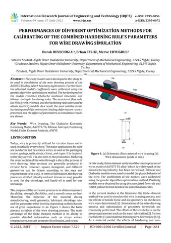
Today, wire is primarily utilized for circular items and is usedpracticallyeverywhere.Themajorapplicationsforwire areconductorandresistancewires,aswellasthepackaging sector,springs,nails,rivets,chains,andropes.Itisdepicted intheplayaswell.Itisalsoseenintheproduction.Reducing thecrosssectionofthewirethroughadieistheprocessof wire drawing. Wire sections are generally produced in circular form. However, square, hexagonal, and different geometries can be drawn according to the area and requirementstobeused.Intermsoflubrication,thedrawing processisdividedintodryandwet.Greaseorsoappowder is used for dry shrinkage, and liquid oil is used for wet shrinkage.
Thepurposeoftheextrusionprocessistoobtainimproved durability,strength,flexibility,andasmoothoutersurface. Therefore, the behavior of the material during manufacturing, mold geometry, lubricant, shrinkage rate, andtheparametersthatdevelopdependingonthesefactors are of great importance to us. Figure 1 shows the basic process variables of the wire drawing process. The main advantage of the finite element method is its ability to provide detailed information such as stress values, temperatures,contactpressuredistribution,andstrain.
Figure 1. (a)Schematic
Inthisstudy,finiteelementanalysisofthetensileprocessof wiresmadeofAA7075T6alloy,whichiswidelyusedinthe manufacturingindustry,hasbeencarriedout.Bilinearand Chabochemodelswereusedtomodeltheplasticbehaviorof the wire. The coefficients of the models were calibrated usingthegeneticalgorithmoptimizationmethod.Plasticity modelswereobtainedbyusingtheassociatedflowruleand Hill48yieldcriterionbesidestheconsolidationrules.
In the current studies in the literature, the finite element methodwasusedtosimulatethewiredrawingprocess,and theeffectsoftensileforceanddiegeometryonthedrawn wireweredetermined[1].Simulationsofthewiredrawing process and optimization of geometric formwork are commonlyperformed.Theeffectsofthetensileforceonthe processparameterssuchasdiewear,lubrication[2],friction coefficients[3]andmaterialthinningweredetermined[4 6]. As a material model, the effects of hardening and non
2022, IRJET | Impact Factor value: 7.529 | ISO 9001:2008 Certified Journal

International Research Journal of Engineering and Technology (IRJET) e ISSN: 2395 0056
Volume: 09 Issue: 07 | July 2022 www.irjet.net p ISSN: 2395 0072
hardeningmaterialmodelsonthewiredrawingprocessare examined and a comparison is made between analytical methodsandthefiniteelementmethod.[7].Therelationship betweenfrictioncoefficient,dieangle,androddiameterwas determinedbyexaminingtheradialstressesonthedrawn wiresurface.Byclassifyingindetailthetypesofinclusions thatcausedamageinwiredrawingoperations,ithasbeen demonstratedthatchemicalalopeciacontainingaluminaand silicate are the main causes of damage [8]. The ability to perform the simulations in a realistic way affects the usability of the found values in the first degree. Unfortunately, there is not yet a single model that can be usedforallplasticdeformationprocessesandissuitablefor all types of materials. In this case, it has been found that isotropicand/orkinematicmodels[9 11]areoftenusedin combinationforsimulationsoftensileprocessing.Itwillnot be sufficient alone for repeated load cases of the loading type.
Experimental stress values were compared with those obtained from the models. As a result, the most suitable hardening model for monotonic and cyclic loading deformation cases is presented, and the effects of model parametersondeformationestimationareshown.
T6
ThematerialofthewireisAA7075 T6.Itselemental compositionisgiveninTable1[12].
Alloy Zn Mg Cu Cr Fe Ti 7075 5.209 2.174 1.876 0.257 0.263 0.044 Mn Al 0.086 Bal.
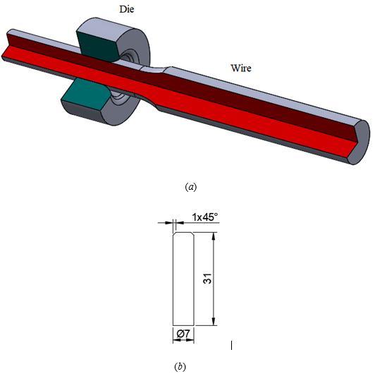
As shown in Figure 2a, monotonic stress and strain curve wereobtainedinthecoordinatesystemusingplatesamples preparedaccordingtotheASTME8standard.
ThetestswereperformedonaShimadzuAutograph100kN testmachinewithadataacquisitionsystemheldbyadigital interface card using a special computer program. Sample elongation was measured by a video type extensometer measuringsystem.Theresultofthemonotonictensiletestis showninFigure2.ThemechanicalpropertiesofAA7075 T6 areshowninTable2.
Table 2. MechanicalpropertiesofAA7075 T6
Density 2.81g/cm3 ElasticityModule 71.7GPa PoissonRatio 0.33 YieldStrength 372MPa MaximumStrength 572MPa r0 0.383 r45 0.692 r90 0.474
Parameters of bilinear isotropic hardening model; yield strength(YS)andtangentmodulusEt;onthedataobtained from the monotonic tensile test; elastic deformation is removed and determined using true stress true plastic deformation values [13]. Elastic deformation from these valuesisexplainedindetailbyKacarandKılıç(2018)[14]. In this study, the bilinear isotropic consolidation rule is combinedwithChaboche'snonlinearkinematichardening rule.
2022, IRJET | Impact Factor value: 7.529 | ISO 9001:2008 Certified Journal
International Research Journal of Engineering and Technology (IRJET) e ISSN: 2395 0056
Volume: 09 Issue: 07 | July 2022 www.irjet.net p ISSN: 2395 0072
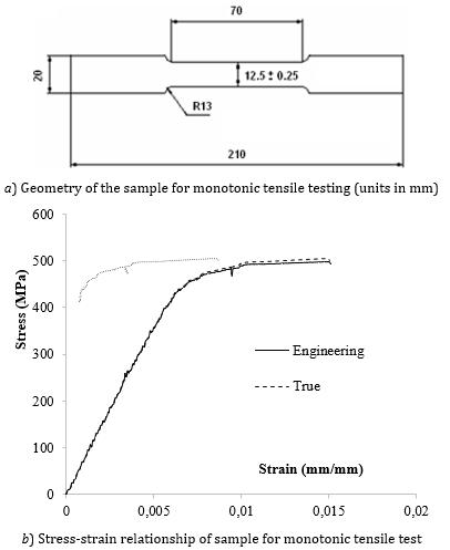
The parameters of the Chaboche hardening rule are yield strength (YS) and material constants , ;ondataobtainedfromonestablecyclicloadingcycle (straincontrolledandsymmetrical)intheformofloading unloading reverse loading;Elasticdeformationiseliminated and the actual stress true plastic deformation values are determined by applying curve fitting algorithms based on nonlinearregression.Sprainsshouldbedelayed[15].Kacar and Toros (2016) revised the retaining system of the test setupanddevelopedanewretainertomodifytheASTME8 typeofspecimenstofitthisnewsetupandthusensurethat the buckling modes are adequately delayed [16]. In this study, this mechanism and sample type were used. The dimensionsofthesamplesaregiveninFigure3
simulate the trans elastic behavior of the material. In this study,therelatedflowrule[17],Hill48yieldcriterion[18], and hardening models were used to form the constitutive equation. As reinforcement models; bilinear isotropic, Chabochekinematics,andcombinationmodelswereused.
The yield criterion specifies a boundary surface in the principal stress space. This limit defines whether the materialshowsflow.Ageneralformulafortheyieldcriterion isgiveninEquation(1).
istheyieldstrengthofthematerial.Itisthesimplestform anddoesnothavecuringeffects.TheHill48yieldcriterionis usedinthisstudy.Theequivalentstress expressionofthe Hill48 yield criterion for a general stress state is given in Equation(2).
inmm)
Here, , i , j=x, y, z representthegeneralizedstressstateat a point on the structure. is the coefficients related to anisotropyvaluesoftheyieldcriterion G, H, F, L, M, and N as intheequationofequivalentstressexpressionand 04590 ,, rrr isgiveninEquation(3).
Iftheequationisrewrittenusingthestressvalues , , , Equation(4)isobtained.
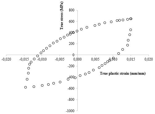
Figure 4. Truestresstrueplasticdeformationdiagram obtainedfromcyclicuniaxialtensiletestingforAA7075 T6atroomtemperature
Figure4showsastablecycleobtainedatroomtemperature usingasymmetricalstraincontrolledloadingmethod.The deformationrangeis±0.015andthedeformationratioisR =−1.
Thedeformationofthewiredrawingprocesswassimulated. Stress and deformation amounts were determined. In the finite elementmethod,structural equationsare needed to
If these coefficients are calculated, F = 0.584249369, G = 0.723065799, H =0.276934201, and N = 0.330105567. In ourstudy,weusedonlythe F, G, and H coefficientsbecause wearedealingwithprimestresses.Calculatedinlinewith r0=0.383, r45=0.692, r90=0.474.
When the flow begins during the plastic deformation process, hardening or softening occurs due to the
International Research Journal of Engineering and Technology (IRJET) e ISSN: 2395 0056
Volume: 09 Issue: 07 | July 2022 www.irjet.net p ISSN: 2395 0072
displacement, that is, the dislocation of the movements. Isotropic hardening rule in determining the expansion or contractionofyieldsurfaces,thekinematichardeningrule provides that the yield surface be postponed until the centerpoint.Ayieldsurfacegeneralformulacontainingthe termsofhardeningisgiveninEquation(5).
The term σ(h) isotropic hardening, and the term is called back stress. Prager, Ziegler, Armstrong Frederic, Chaboche,YoshidaUemorihaveseveral functions.Inthis study,Equation(6),giventhebilinearisotropichardening rule [19], and Equation (7), given Chaboche’s nonlinear kinematic hardening rule [20], were used separately and combined.
YS isyieldstrength,and TM isthetangentmodulus,and is theactualamountofplasticdeformation.
Where istheinversestressvalueatthebeginningofflow, is the initial plastic deformation value, and φ is a sign indicatingthedirectionofloading,calculatedby φ =sgn(σ α)=±1.Therewillbe φ =1foruniaxialdrawingand φ = 1 forpressing.Ifasampledoesnothaveanypre deformation atthebeginningofthetests,theinitialinversestresswillbe =0andtheinitialplasticdeformationvalue =0.Thus, inversestressequations,Eq(9).
WhenwereplacetheinversestressequationofChabochein the equivalent stress expression in the yield criterion, willgenerallybeincludedinthe yield criterion. In the case of a uniaxial tensile test, the equivalentstresswillonlybeequaltothenormalstressin thextensileaxis,ie Thus,theequivalentstress formula in the yield criterion will become Theyieldcriterioncanberewritten asinEquation(10)foruniaxialloadinginthexdirection.
Equations(9)and(10)flowbyusinguniaxialloadingstatus, whichwillhavecomprisedthecombinedhardeningrule
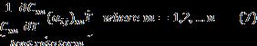
Where m =1,2, , n where n isthetotalnumberofterms, T is thetemperature,and Cm istheconsolidationmodulusforthe m ’thterm.Inaddition, γm isaunitlessvaluecalculatedbythe slopeofthecurve,whichindicatestherateofreachingthe thresholdvalueandmeansareductionrateofconsolidation. Theseparametersmaybedifferentforeachterm. isthe cumulativeplasticdeformationratioandwillbeobtainedby a flow rule. All of these parameters are determined by a nonlinearregressionprocessappliedtoaregularhysteresis cycle.Theregressionisappliedtothetruestress trueplastic deformation cycle obtained from the low cycle stress compressiontypefatiguetest.
Equation(7)isthefirst orderordinarydifferentialequation andmustbesolved.Thescopeofthisstudywillbeobtained as in Equation (8) when Chaboche's first order inverse stress equation is solved by integrating with the assumptionthatthereisnotemperaturechange( ).
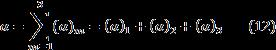
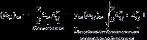
More than one term for more realistic simulations of the plasticdeformationprocesses,inparticularwhensubjected tomultiplerepetitions,and,ifpossible,themorecyclesthe draft object is actually exposed to. The increase in the number of terms in the Chaboche equation gives more accurate results in such successive loads. Therefore, if we writetheChabocheinversestressequationforthreeterms, thefollowingequationswillbeobtained.
for tension case (13a)
International Research Journal of Engineering and Technology (IRJET) e ISSN: 2395 0056
Volume: 09 Issue: 07 | July 2022 www.irjet.net p ISSN: 2395 0072
Table 3. Parametersofthemodelscalculatedby regression(frommonotonicvalues)
compression case (13b)
Asitcanbeinferredfromthesestatements,theterm γ3 does not exist in this equation and the term γ3 is used for rachetingestimatesthatareoutsidethescopeofthisstudy. γ3 termsalonearenotsufficienttodeterminethehysteresis loop.Anothertensile compressiontestconsistingofseveral cycleswithtensilecontrolisrequired,andasmallpositive valueof γ3 cangenerallybegiven[21].
If Equation (13) is substituted in Equation (10), the yield criterionwillnowcontaintheconsolidationrules,ascanbe seen in Equation (14). In this case, the subscripts t and c, respectively,showthetensileandcompressionstates.
The flow rule is required to calculate the direction of the plasticstrainincrease Theflowruleshowshowmuch equivalentplasticdeformation isseenduringmaterial flow.Italso showstherelationship between plasticstress and stress. The general equation of a flow rule is , where λ is the plastic multiplier. f is a scalarfunctionandisalsocalled“plasticpotential’’.Inthis study, the flow criteria function is taken as the plastic potentialfunction.Thisacceptanceiscalledtheassociated flowruleandisageneralcaseformetallicmaterials[22].
As a result of the nonlinear regression process, the yield strength of the bilinear isotropic hardening model was obtainedbyusing YS andtangentmodulus Et and YS, Cm, γm parameters found in the Chaboche equation. Yield values (YS)inbothmodelsarecommon.Inthisstudy,athree term Chabocheequationwasused.
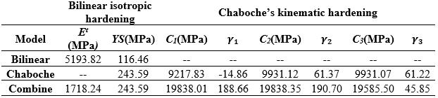
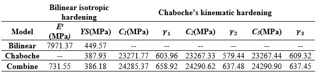
Table 4. Theparametersofthemodelscalculatedby regression(fromcyclicvalues)
Ascanbeseenfromthetables,whilea hardeningrulefor AA7075 T6materialstandsalone,thecalculatedparameters are different from each other. In addition, different coefficientsareobtainedinmonotonicorcyclicdatacases.
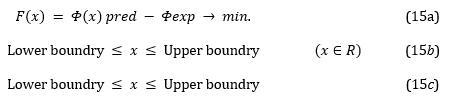
Thefactthatthemodelparametersarefoundbycurvefitting does not mean that the parameters obtained will comply withallkindsofplasticdeformationprocesses.Optimization processesare frequentlyusedforthispurpose.Theinitial materialconstants YS, Et, C1, γ1, C2, γ2, C3, γ3 aredefinedas theinputvaluesoftheoptimizationprocess.AsinEquation (15a), an objective function is determined. For the optimizationprocess,firstdesignpointsaredeterminedand a solution is obtained for the design points obtained in Equation(15b, c).Inordertoseetherelationshipbetween theobtainedresultsandvariables,theKriging[23]method canbeusedtographtheinputvaluesandoutputvaluesand followthechangesbeforeoptimization.
The mathematical meaning of the optimization process, numericalestimationanddeformation,deformation,stress, andsoon.istheminimumsearchforthedifferencebetween experimental measurements of variables. The best parametersthatcanbringthedifferencetozeroornearzero will be a point to the optimum value. At the end of a
2022, IRJET | Impact Factor value: 7.529 | ISO 9001:2008 Certified Journal
International Research Journal of Engineering and Technology (IRJET) e ISSN: 2395 0056
Volume: 09 Issue: 07 | July 2022 www.irjet.net p ISSN: 2395 0072
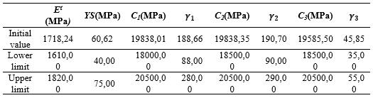
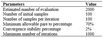
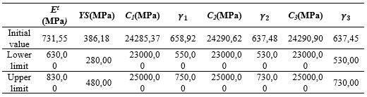
successfullycompletedoptimization,theestimationofthe model with optimized constants should best match the experimentalmeasurement.FEanalysissoftwarewasused for both simulation and optimization [20]. Tables 5 and 6 show the upper and lower limits of the parameters to be optimized.InTable7,theparametersoftheGAmethodused foroptimizationaregiven.
Table 5. Lowerandupperlimitsofdesignvariablesfor monotonicloading
Table 6. Lowerandupperlimitsofdesignvariablesfor cyclicloading
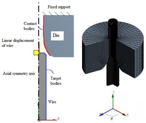
Table 7. GA’sparametersusedintheoptimization.
Themoldandwiremodelswereseparatedusingisquare shapedelements.Thefrictionbetweenthedieandthewire wastakenas0.125tosimulatemetallicmetalcontact.The moldisfixedtothesurfaceshowninthefigurewithabuilt inbracketandismodeledasrigid.Wirematerialismodeled asadeformableobjectusingAA7075 T6materialwiththe datainTables1and2.Adisplacementinthe y directionis defined by restricting the movement of the wire in the x direction. As shown in Figure 6b, this linear displacement wasappliedinatotalof181steps.Ouraimhereistopullthe 7mmdiameterwirefromthe5mmdiametermoldcavity. Toavoidconvergenceproblems,the wireis placeda little behindthecontactpointofthemold.Thisbehaviorprevents excessivedeteriorationordetachmentoftheelementsfrom thecontactsurfaces.Furthermore,whendeformation was appliedtotheendofthewire,abendingproblemoccurred duringthepassageofthediemist.Inordertoovercomethis, deformationstepswereappliedtothebevelledsurfaceby chamferingtheendportionofthewire,thuseliminatingthe convergenceproblem.
Infinite elementanalysis, anaxial symmetric 2D model is used instead of a 3D model to avoid time consuming calculations. The cylindrical coordinate system (x, �� , z) is locatedatthecenterofthewire.Theaxialsymmetryaxisof thefiniteelementmodelislocatedontheyaxis.Theradial directioncorrespondstothexdirection.AsshowninFigure 5,thesymmetricalmodelisplacedinthepositivexdirection consideringtheradialdimensions.
Thewiremovesintothemoldbymovinginthe+ y direction, asindicatedinFigure6b.Atotaldisplacementof90.5mm wasdefined.Itisimportanttonoteherethatthelengthof thewirewillbeshorterasthelengthwillbeshortened.The model is confirmed by comparing the experimentally measuredandestimatedvaluesofthediameterofthedrawn wire. It is then used as input data for the next step, the optimizationprocess,tocalibratethematerialparametersto givetheclosestresulttotheexperimentalvalue.
International Research Journal of Engineering and Technology (IRJET) e ISSN: 2395 0056
Volume: 09 Issue: 07 | July 2022 www.irjet.net p ISSN: 2395 0072
(a)
(b)
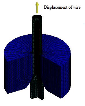
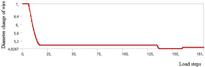

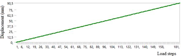
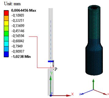
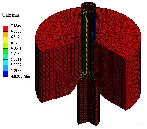
Figure 6. (a) Finite element model for simulation of monotonic plastic deformation, (b) displacement steps appliedtothewire
TheparametersinTables3and4areusedasinitialvalues for the constants of the material models of AA7075 T6. Althoughthediameterofthemoldis5mm,thereareminor deviationsinthediameterofthedrawnwireexitingthedie due to the spring back. The figures show the last step solutionsforallgeometry.
(b) (c)
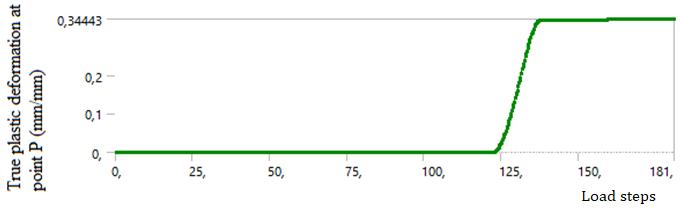
Figure 7. (a) The combination of bilinear isotropic and Chabochekinematicmodelresultsindeformationatthelast stageinthexdirection(b)displacementatpointP(c)actual plasticdeformationofpointP
(a) (b)
International Research Journal of Engineering and Technology (IRJET) e ISSN: 2395 0056
Volume: 09 Issue: 07 | July 2022 www.irjet.net p ISSN: 2395 0072
(c)
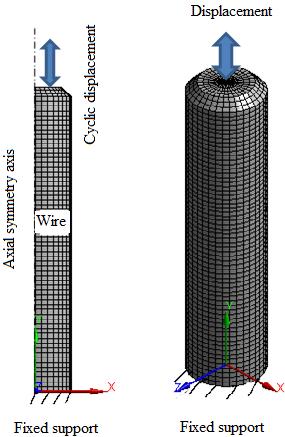
Figure 8. (a) Change in wire diameter during the process (mm) (b) Change in diameter according to load steps (c) Bearingreactions
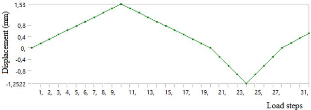
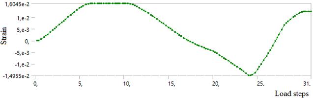
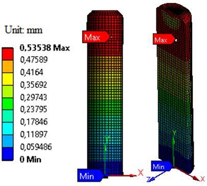
Model parameters to be calculated for cyclic operating conditionsmustbeobtainedusingacyclicprocess.Forthis reason,themodelshowninFigure10wasusedtoperforma separateanalysisforthecyclicstate.Thedifferencebetween themodelandthemodelinthewiredrawingprocessisthat thedisplacementisnotapplieddirectlytothesurface.The displacementswereappliedat31levelsintotal.Thesolution lasted3min52sec.Bothpositiveandnegativedisplacement wereappliedtothetopsurfaceofthewire.Inthisway,the displacementsareappliedwithoutleavingthesurfaceofthe wire.Theapplieddisplacementandtheobtainedpermanent deformationvaluesareshowninFigure9bandc.Ascanbe seenfromFigure11c,adisplacementbetween1.53mmand 1.25mmisrequiredasinFigure9’binordertoproduce± 0.015deformations.Thestressdistributionresultingfrom the displacements applied is shown in Figure 10. The combinedmodelinTable4wasusedfortheanalysis.
(b) (c)
(d)
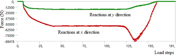
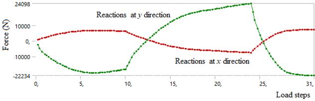
Figure 9. (a) FE model for cyclic plastic deformation simulation, (b) Wire displacement steps, (c) Permanent deformationofwireand(d)Bearingreactions
As can be seen from Figure 9b, a displacement between (1.53mm) ( 1.25mm)boundariesisrequiredasinFigure 9c toproduce2.1%deformation.
(a)
(a)
International Research Journal of Engineering and Technology (IRJET) e ISSN: 2395 0056
Volume: 09 Issue: 07 | July 2022 www.irjet.net p ISSN: 2395 0072
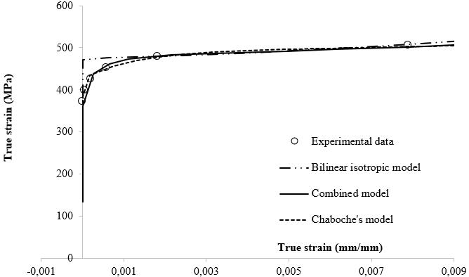
InFigure11,theexperimentaldataandpredictedcurvesare compared with each other using optimised material parameters. Neither the bilinear model nor the Chaboche modelsfittheexperimentaldatawell.Curvesshowthatthe combinedmodelhasthebestimprovedfitofthemodelsof experimentalpoints.
(b)
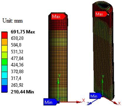
Figure 10. Deformationandstresssolutionresultsobtained usingcombined model,(a)Deformation resultsinthelast step,(b)Hill48stressdistributioninthelaststep
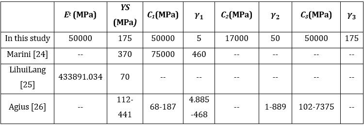
Table 8, 9 and 10 show the values obtained as a result of optimization.
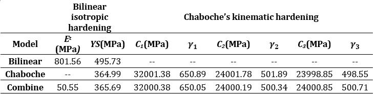
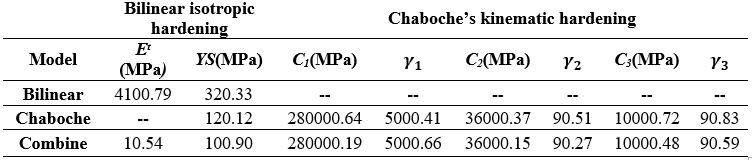
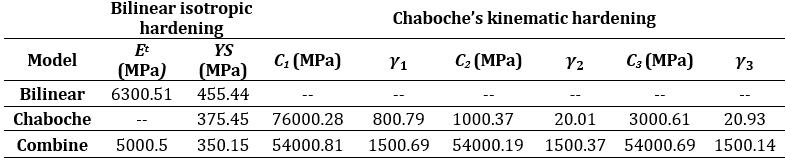
Table 8. Estimatedparametersobtainedfrommonotonic truestresstrueplasticstraindata.
Table 9. Estimatedparametersobtainedfromthe monotonictruestresstrueplasticstraindatawhennodie isused.
Table 10. Estimatedparametersobtainedfromcyclicactual stresstrueplasticstraindata.
(a)
(b)
Figure 11 Estimatedperformancesoftheoptimummodels obtainedformonotonic/cyclicloadingconditionscompared to experimental data (a) Monotonic model estimates (b) Cyclicmodelestimates
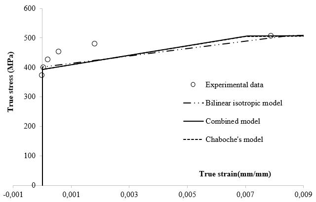
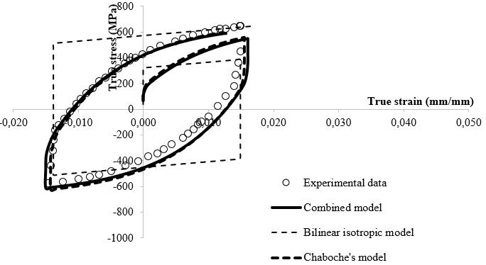
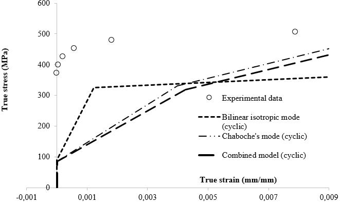
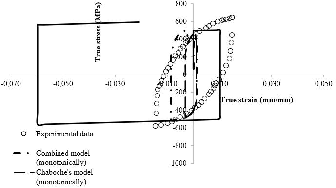
Figure12showsmodelpredictionswhenmonotonicmodels areusedincyclicdeformationprocessesandviceversa.Itis notseentobewell fittoexperimentaldata.
2022, IRJET | Impact Factor value: 7.529 | ISO 9001:2008 Certified
International Research Journal of Engineering and Technology (IRJET) e ISSN: 2395 0056
Volume: 09 Issue: 07 | July 2022 www.irjet.net p ISSN: 2395 0072
(a) (b)
Figure 12. (a) Use of cyclic models in a monotonic deformationprocess.(b)Useofmonotonicmodelsinacyclic deformationprocess
Figure13showsthecurvesinwhichthemonotonicdrawing processisnotusedusingthevaluesinTable9.
Some plasticity models are set using isotropic/kinematic hardening rules in the Hill48 yield criterion with an associated flow rule for FE simulation of a pipe drawing process.Inthisstudy,theoptimizationprocessisperformed todetermineandcalibratetheplasticitymodel’sparameters withmonotonicandcyclingstress strainhardeningcurves. The results revealed that the drawed diameter can be predicted more accurately when the combined model parameters are used. Although there is a small difference betweentheexperimentalandthemodels’hysteresisloops, the diameter predictions are closer to the experimental results.Themainfindingsobtainedfrominvestigationsare listedbelow:
TheHill48criterionhaspredictedthestressvalues moreaccuratelythanvonMises.Duetoanisotropy, thepredictionabilityoftheHill48modelisgreater thanvonMisses.
While a bilinear isotropic hardening rule by itself may be enough to predict the material behavior, whichjustincludesamonotonicloadingcase,onlya kinematicmodelora bilinearisotropic modelare not enough to simulate the cyclic plastic deformation process. Because it includes both isotropicandkinematichardeningtogether.Soitis seen that the combined models provide more accurate predictions for monotonic and/or cyclic loadings.
Figure 13. Estimatedperformanceoftheoptimummodels comparedtotheexperimentaldataobtainedwhenthedieis notusedforthemonotonicloadingcase
Inthecombinedmodel,theelevatedYSmakesthe loopexpanded.While Et isdecreasing,theslopeof the boundary curve also decreases. While C’s are gettingincreased,theroundnessoftheverticesof theloopincreases.While ’saregettingincreased, the slope of the boundary curve decreases. The initialyieldstressofthematerial YS hasnothadany effectontheerrorminimizationperformedbythe curve fittingtool.
International Research Journal of Engineering and Technology (IRJET) e ISSN: 2395 0056
The coefficients optimized for the monotonic hardeningcurvesarenotsuitableforpredictionof cyclicloops.
[1] Leonardo Kyo Kabayama, Simone Pereira Taguchi, GustavoAristidesSantanaMartinez,TheInfluenceofDie Geometry on Stress Distribution by Experimental and FEM Simulation of Electrolytic Copper Wiredrawing, Materials Research, Vol.12, No.3, 281 285, (2009).M. Young, The Technical Writer’s Handbook. Mill Valley, CA:UniversityScience,1989.
[2] Onur Duman, Mustafa Kemal Külekçi, Ultrasonik Titreşimin Tel Çekme İşlemine Etkisi, Pamukkale ÜniversitesiMühendislikBilimleriDergisi,25(4),440 443,(2019).
[3] Andrea Panteghini, Francesco Genna, An engineering analyticalapproachtothedesignofcoldwiredrawing processes for strain hardening materials, 3:279 289, (2010).
[4] IoanaMonicaSas Boca,MariusTintelecan,MarianaPop, Dana AdrianaIluţiu Varvara,AdrianaMariaMihu,The WireDrawingProcessSimulationandtheOptimization of Geometry Dies, 10th International Conference InterdisciplinarityinEngineering,181,187 192,(2017).
[5] Adriana Maria Mihu, Ioana Monica Sas Boca, Ionut Marian,IulianSebastianMihu,DorinaSimonaIanc,Liviu Nistor, Dana Adriana Ilutiu Varvara, Finite Element Analysis of Drawing Wire in Cassette Roller Die, 9th International Conference Inderdisciplinarity in Engineering,22,34 39,(2016).
[6] L. Filice, G. Ambrogio, F. Guerriero, A multi objective approachforwire drawingprocess,8thCIRPConference on Intelligent Computation in Manufacturing Engineering,12,294 299,(2010).
[7] C. J. Luis, J. León, R. Luri, Comparison between finite element method and analytical methods for studying wiredrawingprocesses,JournalofMaterialsProcessing Technology,164 165,1218 1225,(2005).
[8] ÜmitŞenyürek,HüseyinCömert,TelÇekmeProsesive İnklüzyonHasarları,SAUFenBilimleriEnstitüsüDergisi, 6.Cilt,3.Sayı,178 182,(2002).
[9] KazunariYoshidaveHiroakiFuruyaMandreldrawing and plug drawing of shape memory alloy fine tubes used in catheters and stents, Journal of Materials ProcessingTechnology,153 154(2004)145 150
[10] H.Pelletierveark.Limitsofusingbilinearstress]strain curve for finite element modeling of nanoindentation
responseonbulkmaterials,ThinSolidFilms379,2000, 147 155
[11] Feng Lua ve Jinquan Xu Evaluation of cyclic inelastic responseinfrettingbasedonunifiedChabochemodel, InternationalJournalofFatigue27(2005)1062 1075
[12] S.Sreenivasan,SerimantKumarMishra,KrishnaDutta, Ratceting strain and its effect on low cycle fatigue behaviorofAl7075 T6alloy
[13] K. Saanouni, J.L. Chaboche, 3.06 “Computational Damage Mechanics: Application to Metal Forming Simulation” Comprehensive Structural Integrity, Pergamon,2003,Pages321 376,
[14] Kacar,İ.andS.Kılıç,PekleşmeKuralları,inMühendislik Alanında Yenilikçi Yaklaşımlar, P.D.T. Güngör, et al., Editors. 2018, Gece Kitaplığı: ANKARA / TURKEY. p. 175 194.
[15] V.M.J. Sharma, G.S. Rao, S.C. Sharma, K.M. George, LowCycleFatigueBehaviour of AA2219 T87 at RoomTemperature, Materials Performance and Characterization3(1)(2014)103 126.
[16] İ. Kacar, S. Toros, Buckling Prevention Conditions on Cyclic Test Samples, in: M. Özcanlı, H. Serin, A. Çalık (Eds.) BucklingPrevention Conditions on Cyclic Test Samples,ÇukurovaÜniversitesi,Adana,2016,pp.4791 4798.
[17] D.R.Bland,Theassociatedflowruleofplasticity,Journal oftheMechanicsandPhysicsofSolids,Volume6,Issue 1,1957,Pages71 78
[18] R. Hill, A theory of the yielding and plastic flow of anisotropicmetals,ProceedingsoftheRoyalSocietyof London. Series A. Mathematical and Physical Sciences 193(1033)(1948)281 297.
[19] R. Hill, A theory of the yielding and plastic flow of anisotropicmetals,ProceedingsoftheRoyalSocietyof London. Series A. Mathematical and Physical Sciences 193(1033)(1948)281 297.
[20] Support_Ansys, Video Demo: Material Curve Fitting, 2016.
https://support.ansys.com/staticassets/ANSYS/staticas sets/techmedia/material_curve_fitting.html.
[21] Sharcnet(c). 32.2. Modeling. 2018; Available from: https://www.sharcnet.ca/Software/Ansys/16.2.3/enus /help/ans_tec/teccurvefitchabmodel.html.
[22] Mohsen Safaeii Wim De Waele, Shun lai Zang, EvoluationofAssociatedandNon AssociatedFlowMetal Plasticity;ApplicationforDC06DeepDrawingSteel,Key EngineeringMaterialsVols.504 506(2012)pp661 666.
Volume: 09 Issue: 07 | July 2022 www.irjet.net p ISSN: 2395 0072 © 2022, IRJET | Impact Factor value: 7.529 | ISO 9001:2008 Certified Journal | Page1674
International Research Journal of Engineering and Technology (IRJET) e ISSN: 2395 0056
Volume: 09 Issue: 07 | July 2022 www.irjet.net p ISSN: 2395 0072
[23] Irfan Kaymaz, Application of kriging method to structural reliability problems, Structural Safety 27 (2005)133 151
[24] M.Marini,V.Fontanari,M.Bandini,M.BenedettiSurface layermodificationsofmicro shot peenedAl 7075 T651, Experiments and stochastic numerical simulations, Surface&CoatingsTechnology321(2017)265 278
[25] Lihui Lang ve ark. Pressure rate controlled unified constitutive equations based on microstructure evolutionforwarmhydroforming,JournalofAlloysand Compounds574(2013)41 48
Name Surname: Burak DEVECIOGLU


Address: Hayriye District, Tuzcular StreetNo:22/6Eskişehir/TURKEY
Name Surname: ErhanCELIK Address: AsagiHisarStreet4599.Sk. No:15/3Antalya/Manavgat/TURKEY
Name Surname: Merve ERTUGRUL
Address: Mimar Sinan District, Yunus Emre Street No: 26/1 Istanbul/TURKEY
2022, IRJET | Impact Factor value: 7.529 | ISO 9001:2008 Certified Journal