International Research Journal of Engineering and Technology (IRJET) e ISSN: 2395 0056

Volume: 09 Issue: 07 | July 2022 www.irjet.net p ISSN: 2395 0072
International Research Journal of Engineering and Technology (IRJET) e ISSN: 2395 0056
Volume: 09 Issue: 07 | July 2022 www.irjet.net p ISSN: 2395 0072
2
1M.Tech student, Dept. of Civil Engineering, St. Joseph’s College of Engineering & Technology, Kerala, India 2Assistant professor, Dept. of Civil Engineering, St. Joseph’s College of Engineering & Technology, Kerala, India ***
Abstract In structural engineering, the main purpose is to maintain structural stability against the effect of various forces acting on the structure. Also, when comparing steel and RC structures, the design of the steel structure focuses primarily on the joints. Proper and effective connections play an inevitable role in maintaining the structural stability of the steel structure. Currently, bolts are widely used fastener to connect steel connections. This project is an attempt to determine the influence of shear capacity by gauge distance on bolted connection. In order to achieve this objective, Finite Element Analysis were carried out in Ansys workbench 2021 r2. The analysis consists of 24 parametric studies that are carried out on 24 models. Each models are differ by the types of bolt hole clearance, bolt diameter, gauge distance and cleat angle used. The entire parametric study is mainly followed by using 10.9 High Yield Friction Grip (HYFG) bolt of diameter 16 mm and 20 mm.
Key Words: Bolted connection, Finite Element Analysis
Anysteelstructureismadeupofvariousmembers,suchas beam,columns,andtensionmembers,whicharefastenedor connectedtooneanother,usuallyatthememberends.Many members in a steel structure may themselves be made of different components such as plates, angles, I beams, or channels.Thesedifferentcomponentshavetobeconnected properlybymeansoffasteners,sothattheywillacttogether asasinglecompositeunit.Theadvantagesofprefabricated steel structures include rapid construction, less environmentalpollutionandbetter qualitycontrolthanthe conventional on site built structures. The use of prefabricated steel structures helps to achieve the industrializationofconstruction.
Anystructure'sconnectionsareacrucialcomponentandare constructedmoreconservativelythanitsmembers.Thisis duetothefactthatconnectionsaremoredifficulttoanalyse than members, and there is a significant gap between analysisandrealbehaviour.Designanddetailsarecrucial for the economy of the structure because it makes up majorityofthecostforstructuralwork.Priortodesigning the structural system and its members, the type of connection to be used must be chosen because it affects memberdesign.Forinstance,thenetareaisestimatedwhen
designing fastened tension members by assuming an appropriate no. of bolts and bolt diameter, based on experience.
Steel constructions' connections go into one of three categories:1)riveted,2)bolted,or3)weldedconnections. Boltedconnectionswillprogressivelytaketheroleofriveted connections,whicharestillutilisedinsomesituations.This isbroughtonbytheconnection'sintrinsicinefficiency,the expensivecostofinstallation,andtheweakrivetstrength. Becausenoholesneedtobeboredinthemember,welded connectionshavetheadvantageofbeingmoreefficient.But field welding having their own challenges and time consuming.Weldedconnectionsarealsopronetofailureby cracking when subjected to repeated cyclic loads from fatigue, which may be brought on by working loads like trainscrossingabridge(high cyclefatigue)orearthquakes (low cycleFatigue).Ithasbeendiscoveredthataparticular kind of fastened connection using High Strength Friction Grip(HSFG)boltsperformsbetterundersuchcircumstances than the traditional black bolts meant to resist primarily static pressure. The alloy steel used to create HSFG bolts ranges in grade from 8.8, 10.9, and 12.9. The most typical contain a medium carbon concentration and a so called generalgradeof8.8,whichmakesthemlessductile.Bolted connectionsarealsoeasytoinspectandreplace.Thechoice ofusingaparticulartypeofconnectionisentirelythatofthe designer and he should take his decision based on a good understanding of the connection behaviour, economy and speedofconstruction.
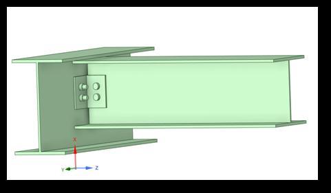
Bolted joints are one of the most common elements in constructionandmachinedesign.Theyconsistoffasteners suchas,bolt.Boltisametalpinwithaheadatoneendanda shankthreadedatanotherendtoreceivea nut.toprevent thetreadedareaoftheboltfrombearingontheconnecting piecesand to evenlydistributethe clampingstrain on the fastenedmember,steelwashersareoftenplacedunderthe bolt head and nuts. End connections in tension and compressionmemberscanbemadeusingaboltconnection. By creating an appropriate balance between the joint and bolt stiffness, the bolt and clamped components of the tension joint are designed to pass an applied tension load throughthejointviatheclampedcomponents.
International Research Journal of Engineering and Technology (IRJET) e ISSN: 2395 0056
Volume: 09 Issue: 07 | July 2022 www.irjet.net p ISSN: 2395 0072
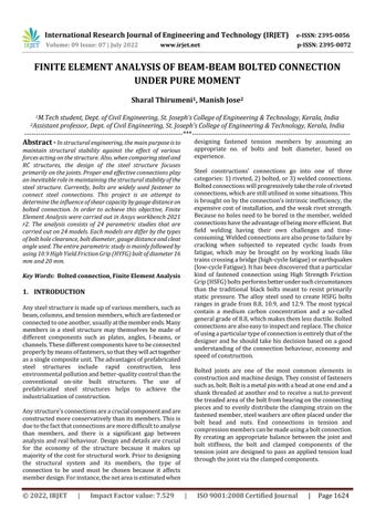
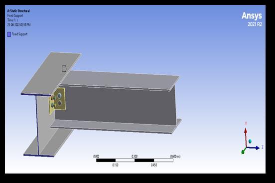
Primarybeamsection:ISHB350
Primarybeamlength:1500mm
Secondarybeamsection:ISHB250
Secondarybeamlength:750mm
Boltdiameter:16mmand20mm
Cleatanglesection:150x150x8mm,forM16bolts
170x170x10mm,forM20bolts
Yieldtensilestrengthofbeam:250MPa
Ultimatetensilestrengthofbeam:460MPa
Boltgrade:10.9grade
Yieldtensilestrengthbolt:900MPa
Whenbeamconnectionsaremadewithbolts/rivets,holes willbepunchedordrilledintheweborflangesofthebeam. Thetestsonsteelbeamsrevealthattheirfailureisbasedon strength of compression flange even though there may be boltholesinthetensionflange.Theeffectsofboltholesin the tension flange of beams, particularly for flexure, are negligible and are not serious for two reasons. Bolt holes reduce the section modulus and thus affect the bending stresses.Asregardstheboltholes,thenormalpracticeisto deductalltheholesevenonthecompressionflange.Thisis becausethestrengthofasteelbeamdependsonthestrength of its compression flange and thus any open hole in the compressionflangeaffectsthebeamstrengthmorethatbya holeintensionflange.
Incaseifholesaremadeforpipesandconduits,extraplates areprovidedallaroundtheholestostiffenthecutportion. Whenholesare made in the web,thesedo not reduce the sectionmodulus;theshearisminimumandmayhavelittle effectonthestrengthofthegirder.Iftheholeislocatednear the support in the region of high shear, the additional bendingstressesproducedbythisshearmustbeaddedto the conventional bending stresses from the applied beam load.
Todeterminetheshearcapacityofbeam beambolted connection.
Ultimatetensilestrengthbolt:1000MPa
Todeterminearelationbetweencenter centerbolt holedistanceandshearcapacityofboltedconnection.
Todeterminetheinfluenceofdirectionofslottedbolt holes.
The ultimate purpose of this project is to determine the influenceofgauge/pitchdistanceonshearcapacityofbolted connection.Theanalysisistakeoverbycoveringaround24 models and each model is differ by the type of bolt hole clearance,gaugedistance,boltdiameterandcleatangle.The boltof16mmand20mmdiameterwithHighYieldFriction Grip (HYFG) bolt of grade 10.9 are used to perform the analysis. The 10.9 grade bolt implies, they can bear an ultimate tensile strength of 1000 MPa and yield tensile strength of 900 MPa. Since it’s a HYFG bolted connection, eachboltrecommendsapretensionforce,whichisfollowed as per IS 4000:1992. According to IS 4000:1992, this pretension force will vary according to the diameter and grade of bolt. The load transferring in a HYFG bolted connectionismainlydependsupon thefrictional support, thatofferingbythecontactsurfaces.So,tighteningofbolts playsacrucialroletoachievingsufficientfrictionalsupport. As already said, the parametric study for the analysis are follows;
International Research Journal of Engineering and Technology (IRJET) e ISSN: 2395 0056
Volume: 09 Issue: 07 | July 2022 www.irjet.net p ISSN: 2395 0072
Table 1:Parametricstudy
Model No. Bolt Diameter (mm)
Gauge Distance (mm)
Type Of Bolt Hole Clearance 1 16 40 Normalclearance 2 16 48 Normalclearance 3 16 56 Normalclearance 4 16 64 Normalclearance 5 16 40 Verticalslotted 6 16 48 Verticalslotted 7 16 56 Verticalslotted 8 16 64 Verticalslotted 9 16 40 Horizontalslotted 10 16 48 Horizontalslotted 11 16 56 Horizontalslotted 12 16 64 Horizontalslotted 13 20 50 Normalclearance 14 20 60 Normalclearance 15 20 70 Normalclearance 16 20 80 Normalclearance 17 20 50 Verticalslotted 18 20 60 Verticalslotted 19 20 70 Verticalslotted 20 20 80 Verticalslotted 21 20 50 Horizontalslotted 22 20 60 Horizontalslotted 23 20 70 Horizontalslotted 24 20 80 Horizontalslotted
Thevariationofgaugedistanceweretakenonthebasisof minimum gauge distance as per IS 800:2007. The code recommendeda minimumgaugedistanceof2.5timesthe nominalboltdiameter(D).ForfirstmodelIpreferagauge distanceof2.5D.Thenitgraduallyincreasesas3D,3.5D,4D respectively for normal, vertical slotted and horizontal slottedboltholeclearance.Forallmodels,supportcondition andloadingmechanismaresame.
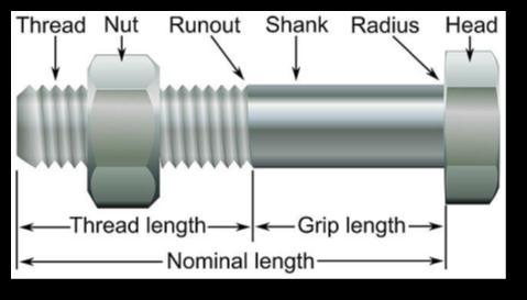
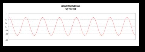
Insteadofnormalloading,cyclicloadingwereappliedonthe beamsectionasshowninfig3.Fig4&5showsthesupport condition and application of moment in primary beam sectionrespectively.
Fig 3: Graphofloadingtype
Fig 4: Supportcondition
Fig 5:Momentapplication
International Research Journal of Engineering and Technology (IRJET) e ISSN: 2395 0056
Volume: 09 Issue: 07 | July 2022 www.irjet.net p ISSN: 2395 0072
Chart 1: Shearcapacityof16mmboltwithhorizontal slottedbolthole
The above graph shows that, while increasing the gauge distance from 2.5 times the bolt diameter (D), the shear capacityoftheboltedconnectionincreasesfrom54.64KNto 131.68 KN. For further increment of gauge distance the shearcapacityslightlyfallsdown.Whenthegaugedistance cross3.5Dto4Dtheshearcapacityvalueslightlyfallsdown, becauseofthereductionincompressiveforcebetweenthe contactsurfaceswhichformedduetothepretensionforce onbolt.
Chart 3: Shearcapacityof16mmboltwithhorizontal slottedbolthole
Chart3showsthat,whileincreasingthegaugedistancefrom 2.5 times the bolt diameter (D), the shear capacity of the bolted connection increases from 58.72 KN to 129.54 KN. Forfurtherincrementofgaugedistancetheshearcapacity slightlyfallsdownto116.582KN.Whilecomparedwiththe normalboltholeclearancethemaximumvalueobtainedat 3.5D.
Chart 2:Shearcapacityof16mmboltwithverticalslotted bolthole
The above graph shows that, while increasing the gauge distance from 2.5 times the bolt diameter (D), the shear capacityoftheboltedconnectionincreasesfrom79.675KN to113.54 KN.Forfurtherincrementofgaugedistancethe shear capacity slightly falls down to 88.24 KN. While comparedwiththenormalboltholeclearancethemaximum valueobtainedat3D.
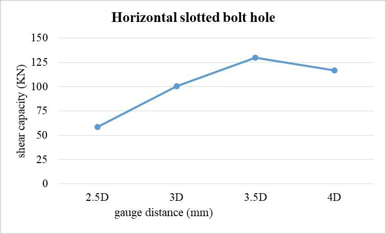
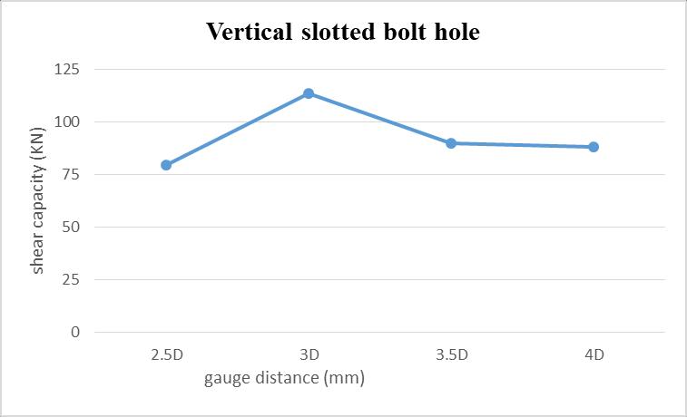
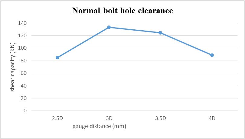
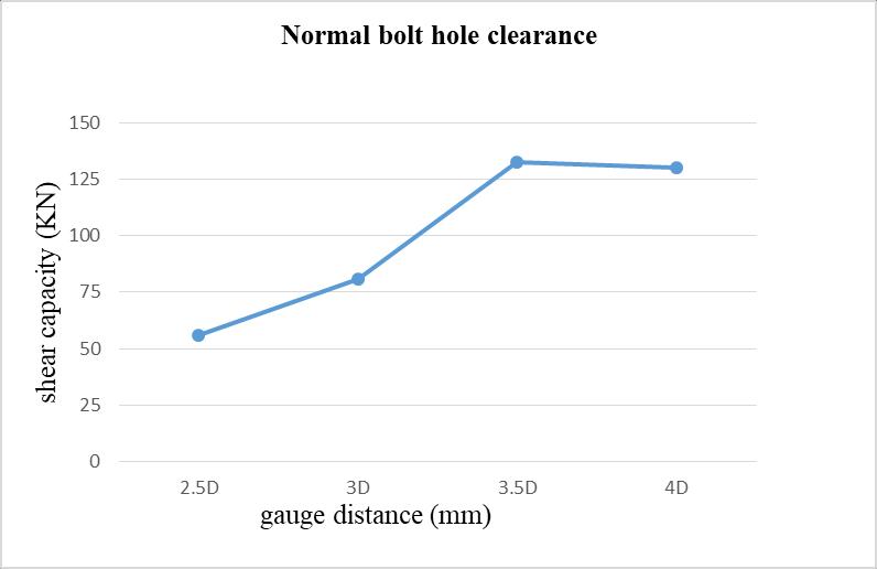
Chart 4: Shearcapacityof20mmboltwithnormalbolt holeclearance
The above graph shows that, while increasing the gauge distance from 2.5 times the bolt diameter (D), the shear capacityoftheboltedconnectionincreasesfrom85.12KNto 133.48 KN. For further increment of gauge distance the shearcapacityslightlyfallsdown.Whenthegaugedistance cross3Dto4Dtheshearcapacityvalueslightlyfallsdown.
International Research Journal of Engineering and Technology (IRJET) e ISSN: 2395 0056
Volume: 09 Issue: 07 | July 2022 www.irjet.net p ISSN: 2395 0072
shearcapacityoftheconnectionwereincreaseswhen gauge distance changes from 2.5 times the bolt diameter,D(40mm)to3.5D.Forfurtherincrementof gaugedistancethevalueslightlydropsdown.
From the analysis of 16mm bolt with vertical slotted bolt hole (model 5 to model 9), we could understood thattheshearcapacityontheboltedconnectionwere increaseswhengaugedistance changesfrom2.5times the bolt diameter, D to 3 D. For further increment of gaugedistancethevaluegraduallyfallsdown.
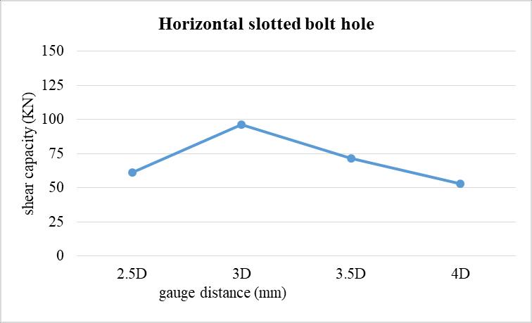
Chart5showsthat,whileincreasingthegaugedistancefrom 2.5 times the bolt diameter (D), the shear capacity of the bolted connection increases from 93.36 KN to 116.28 KN. Forfurtherincrementofgaugedistancetheshearcapacity slightly falls down to 88.80KN. When the gauge distance cross3Dto4Dtheshearcapacityvalueslightlyfallsdown.
Bycomparingthefirst12models,itisunderstoodthat there will limitationstoincreasingthegaugedistance forverticalslottedboltholes.Notonlythat,theboltsina row(aspermodel)canarrangeintwoways.Bothbolts at upward portion of slotted hole and both are in downward portion of the slotted hole. Similarly for horizontalslottedboltholetoo.Sincewedoesn’tapply any lateral force, it doesn’t show any considerable changesinvalues,thatasperappliedloadingcondition.
Byanalysingthemodelsfrom13to24,themaximum shearcapacitywereoccurredat3Dgaugedistance.For furtherincrementofcentretocentreboltholedistance, shear capacity decreases. M20 bolts are used for performingtheanalysisonthesemodels.
1. Zhao, J., et.al, “Finite element analysis of the shear capacity of stainless steel blind rivet connections”, JournalofConstructionalSteelResearch,2021,pp12.
Abovegraphshowsthat,whileincreasingthegaugedistance from2.5timestheboltdiameter(D),theshearcapacityof theboltedconnectionincreasesfrom61.68KNto96.32KN. Forfurtherincrementofgaugedistancetheshearcapacity slightly falls down to 52.97 KN. When the gauge distance cross3Dto4Dtheshearcapacityvalueslightlyfallsdown
The study follows the Finite Element Analysis (FEA) on beam beamboltedconnectionundervariousparametric study. Conclusion of this analysis were performed by comparing the results obtained from 24 models. Here showsthedetailedconclusion,whichare
WhileanalysingtheresultsofM16boltwithnormalbolt holeclearance,andhorizontalslottedbolthole,(model 1 4andmodel9 12),wecanabletoconcludethat,the
2. Sun, L, et.al, “Studies on T shaped one side bolted connection to hollow section column under bending”, JournalofConstructionalSteelResearch,2020,pp21
3. Cai,Y.,et.al,“Effectsofenddistanceonthinsheetsteel boltedconnections”, EngineeringStructures, 2019, pp 13.
4. Elliott, M. D., et.al, “Behaviour and strength of bolted connectionsfailinginshear”,JournalofConstructional SteelResearch,2019,pp10.
5. Liu, X. C., et.al, “Seismic performance of bolted connection of H beam to HSS column with web end plate”,JournalofConstructionalSteelResearch, 2019, pp15.
6. Movaghatia, S, et.aL, “Experimental study on the nonlinear behavior of bearing type semi rigid”, EngineeringStructures,2019,pp10.
International Research Journal of Engineering and Technology (IRJET) e ISSN: 2395 0056
Volume: 09 Issue: 07 | July 2022 www.irjet.net p ISSN: 2395 0072
7. Wang, Y. B., et.al, “Shear behavior of lap connection usingone sidebolts”,EngineeringStructures,2019,pp 64 85.
8. Wang, D. B., et.al, “Progressive collapse behaviour of endplate connections to cold formed tubular column with novel slip critical blind bolts”, Thin Walled Structures,2018,pp404 416.
9. Liu, P. M., et.al, “ Behavior of one side bolted T stub throughthreadholesundertensionstrengthenedwith backingplate”,JournalofConstructionSteelResearch, 2017,pp53 65.
10. Wulan,T.Y.,et.al,“Numericalinvestigationonstrength and failure modes of thread fixed one side bolted T stubsundertension”,EngineeringStructures,2017,pp 15 36.
11. Zhu,M,et.al,“Tensionstrengthanddesignmethodfor thread fixed one side bolted T stub”, Engineering Structures,2017pp918 933.
12. Grimsmo, E. L., et al, “Failure modes of bolt and nut assemblies under tensile loading”, Journal of ConstructionalSteelResearch,2016,pp15 25.
13. Wang, W.A., et.al, “Yield and ultimate strengths determinationofablindboltedendplateconnectionto squarehollowsectioncolumn”,EngineeringStructures, 2016,pp345 369.
14. Thai, H. T., et.al, “Finite element modelling of blind boltedcompositejoints”,JournalofConstructionSteel Research,2015,pp339 353.
15. Wang, X. T, et.al, “Numerical analysis of the seismic behaviourof a squareconcrete filledsteel tube frame with through bolt end plate joints”, Engineering Structures,2015,pp154 162.
16. Wang, J. F, et.al, “Structural performance of one side bolted end plate joints to concrete filled thin walled steeltubularcolumns”,Thin WalledStructure,2012,pp 54 68.
17. Lee, J. et.al, “One side bolted T stub connections to unfilledhollowsectioncolumnsinlowrisestructures”, JournalofConstructionSteelResearch, 2010,pp981 992.
2022, IRJET | Impact Factor value: 7.529 | ISO 9001:2008 Certified Journal