International Research Journal of Engineering and Technology (IRJET) e ISSN: 2395 0056

Volume: 09 Issue: 07 | July 2022 www.irjet.net p ISSN: 2395 0072
International Research Journal of Engineering and Technology (IRJET) e ISSN: 2395 0056
Volume: 09 Issue: 07 | July 2022 www.irjet.net p ISSN: 2395 0072
1 Assistant Professor, Department of Aeronautical Engineering 2, 3, 4 UG Student, Department of Aeronautical Engineering Hindusthan Institute of Technology, Coimbatore, India ***
Abstract A Radio controlled (model) aircraft(oftencalled RC aircraft or RC plane) is controlled remotely by a hand held transmitter and a receiver within the craft. Flying RC aircraft as a hobby has been growing worldwide with more efficient motors (both electric and miniature internal combustion and jet engines) lighter and more powerful batteries and less expensive radio systems. After designing the aircraft wing, fabrication is one of the important factors to be considered. Fabrication mainly depends on the type of material employed in manufacturing the aircraft by considering the availability, cost, durability, strength and how easily it can be made into required shape. This paper is based on designing a light weight, electronically controlled glider with operating frequency of 2.4 GHz. This paper did not concentrated on electronic components as the components used are readily available in markets and need not be programmed by the users. The aircraft wing considered in this paperwasdesigned to have optimum lift and drag characteristics. The aerodynamic characteristics over thewinghadbeenvalidated with the experimental data using low subsonic wind tunnel.
realaircraftwhichfliesandoperatesbythesameprinciples asitsfullscalecounterpart [3].The onlydifferenceissize and weight. Models fly at anywhere between 20 and 150 MPH with the average trainer being between 40 and 60 MPH.Thesearenotslowvehicles,norcantheybeflownina normal backyard. And just like their bigger brothers, they requiredalearnedskilltobecontrolledproperly.Itisnot simplyamatterofpushingabuttontotakeoff,anotherto land,etc.
There were 3 choices for the types of wing we could use, Rectangular,EllipticalandTapered.Themostcommonlyused wingforRCplanesareRectangular[3]
KeyWords: RC Aircraft, Wingspan, Lift, Angle of attack, Drag,Batteries
RCplanerepresentsRadioControlAircraftorAirplaneisa small flying machine that is controlled remotely by an operatoronthegroundusingahand heldtransmitter.The transmittercommunicateswithareceiverwithinthecrafts thatsendssignalstoServomechanisms(servos)whichmove thecontrolsurfacesbasedonthepositionofjoysticksonthe transmitter. The control surfaces, in turn, affect the orientation of the plane [1]. Flying RC aircraft as a hobby grewsubstantiallywithimprovementsinthecost,weight, performance and capabilities of motors, batteries and electronics.Awidevarietyofmodelsandstylesisavailable [2]. The earliest examples of electronically guided model aircraftwerehydrogen filledmodelairshipsofthelate19th century.Theywereflownasamusichallactaroundtheatre auditoriumsusingabasicformofsparkemittedradiosignal. During World war II, the U.S Army and Navy used radio controlled planes called Radio planes as artillery target drones [4]. The first thing one must realize about a radio controlledmodelaircraftisthatitisnotatoy.Themodelisa
The rectangular wing is the best wing for usage from a manufacturabilitypointofview.Therectangularwinghasa tendencytostallrestatthewingrootandprovidesadequate stallwarning,adequateaileroneffectiveness,andisusually quitestable.Itisalsooftenfavoredforthedesignoflowcost, lowspeedR/Cplanes.

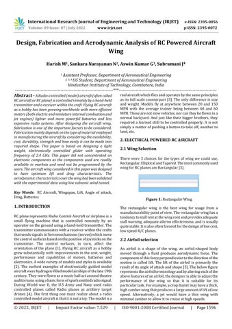
An airfoil is a shape of the wing, an airfoil shaped body moved through a fluid produces aerodynamic force. The componentofthisforceperpendiculartothedirectionofthe motion is called lift. The lift of the airfoil is primarily the resultofitsangleofattackandshape[5].Thebelowfigure representstheairfoilterminologyandbyalteringeachofthe abovefeaturesofanairfoil,thedesignerisabletoadjustthe performance of the wing so that it is suitable for its particulartask.Forexample,acropdustermayhaveathick, highcamberwingthatproducesalargeamountofliftatlow speed. Alternatively, a jet would have a thin wing with minimalcambertoallowittocruiseathighspeeds.
International Research Journal of Engineering and Technology (IRJET) e ISSN: 2395 0056
Volume: 09 Issue: 07 | July 2022 www.irjet.net p ISSN: 2395 0072
Ailerons:
These are the control surfaces situated at the trailing edgeofthewingtogiveittherollmotion.Aileronsmovein oppositedirectiontoeachotherthatistheyhavedifferential action.
Rudder:
Fuselagedesignfocusedonthreedifferentmodels,namely ConventionalMonoplane,Bi PlaneandN Plane Whilelifting the fuselage, one could potentially reduce wing loading, whichwasthepotentialproblemofexecutingalow weight construction along with the excessive airfoil thickness to accommodate a variety of potential loads. Thus a conventionaldesignwasfoundtobeoftenfavoredwithinthe model building community due to ease of construction. ThereforeinthispapertheConventionaltypefuselagewas used
The empennage also knownas the tail or tail assembly,of mostaircraftgivesstabilitytotheaircraft,inasimilarwayto thefeathersonanarrow.Mostaircraftfeatureempennage incorporating vertical and horizontal stabilizing surfaces whichstabilizetheflightdynamicsofpitchandyaw,aswell as housing control surfaces. In spite of effective control surfaces, many early aircraft that lacked stabilizing empennage were virtually not flyable. Today, only a few (oftenrelativelyunstable)heavierthanairaircraftareableto flywithoutempennage.
Thereare 3different tail designsnamely Conventional,V TailandH Tail WhiletheH Tailincreaseseffectivenessof thehorizontalcontrolsurfacesthroughthewinglets,italso adds increased weight to the design since we require a numberofverticalsurfaceswiththeircontrolservos,which may not be considerable. While the V Tail provided a numberofbenefits,theteamfeltthatwecouldgetthesame performancecharacteristicsfromasimplerdesigngiventhe speed we were traveling at. Additionally, no weight was expected to be saved by using a more complicated tail design.
TheConventionaldesigniswellknownforitslowriskand easeofcontrolandmanufacturability.Aconventionaldesign isalsowidelyusedbecauseitisthemostefficienttaildesign forthespeedR/Cplanesareexpectedtoflyit.Andsothe ConventionaldesignisgoodforlowspeedRCplanes.
It is a control surface unites with vertical stabilizer to controltheyawmotionoftheaircraft.
Elevator:
It is a control surface unites with horizontal stabilizertocontrolthepitchingmotionoftheaircraft.
Thebasicparameterstobeconsideredarewingspan,chord length,Planformarea,Tipchord,rootchord,aerodynamic centreetc.
1.
Chord refers to the imaginary straight line joining the leadingandthetrailingedgesofanairfoil.Thechordlength isthedistancebetweenthetrailingedgeandthepointonthe leading edge where the chord intersects the leading edge. ThedesignedChordlength(c)forthewingis11cm.
Itisthemaximumextentacrossthewingofanaircraftorof abirdorotherflyinganimalmeasuringfromtiptotip.The designedWingspan(b)ofthewingis55cm.
The aspect ratio of the wing is the ratio of its span to its mean chord. It is equal to the square of the wing span dividedbythewingarea.Thus,alargenarrowwinghasa high aspect ratio, where as a short, wide wing has a low aspectratio.
AspectRatio(AR)=b/c
Where, b Wingspan c Chordlength
AR=55/11
International Research Journal of Engineering and Technology (IRJET) e ISSN: 2395 0056
The designed aspect ratio of the wing is 5 because our aircraft is homebuilt so according to the given we have chosenittobeinthecorrectrange.
4.
It is the area of the wing as viewed from above the wing, lookingalongtheliftdirection Swing=b^2/ARcm^2=3025/5
Anaircraftwithalowwingloadinghasalargerwingarea relativetoitsmass,ascomparedtoanaircraftwithahigh wingloading.Thefasteranaircraftflies,themoreliftcanbe producedbyeachunitofwingarea,soasmallerwingcan carrythesamemassinlevelflight.
Wingloading=bodymass/Swinggm/cm^2 =191/605gm/cm^2 =0.3157gm/cm^2
Wingloadingmustnotexceed0.6 1.3gm/cm^2,soitisin thecorrectrange.
Taper ratio is defined as the wing span divided by the averagechord.Ratioofthechordatthetiptothechordat therootanglebetweenthelineof25%chordpointsandthe longitudinalaxis.
Wecallthechordlengthnearthefuselageisrootchord.
CROOT=2*Swing/b*(1+TR) =2*605/55*(1+1) =1210/110 =11cm ItisaRectangularStraightwingsoCTIPisalsosame.
8.AerodynamicCentre(x):
Theaerodynamiccentreisthepointatwhichthepitching moment coefficient for the aerofoil does not vary with lift coefficient (angle of attack), so this choice makes analysis simpler.
X=(CROOT C)+C/4
=(11 11)+11/4=2.75cm
Wingisthemostimportantpartoftheplanewhichprovides lift,whichcausestheplanetofly.Thetypeofwingwehave selectedismonoplane, whichismostpopularlyused over multi plane configuration because the adjacently placed wingsgeneratemoredragandreduceefficiency.
ThepositionofthewingonthefuselageisHighwingwhich is attached to the higher position of the fuselage, it gives stableflight,anditisnotaerobatic.
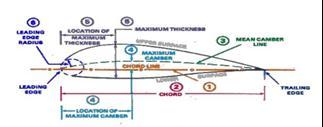
We have chosen Asymmetrical airfoil, because the asymmetricalairfoilhasahighercoefficientofliftthanthe symmetricalairfoil.Onasymmetricalairfoils,thetopedgeis shapeddifferentlythanthebottomedge,whichchangesthe way air flows over it. This causes the air to move faster, whichcreatesmorelift.Theasymmetricalaerofoilwehave usedisGOTTINGEN526.
Figure 3: Gottingen 526 Airfoil
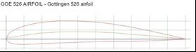
The lift coefficient (CL) is a dimensionless coefficient that relatestheliftgeneratedbyaliftingbodytothefluiddensity aroundthebody,thefluidvelocityanassociatedreference area.Aliftingbodyisafoiloracompletefoil bearingbody such as a fixed wing aircraft. The plot of lift coefficient versusAngleofattackoverGottingen526Airfoilisshownin figurebelow.
Figure 4: CL vs AOA
Volume: 09 Issue: 07 | July 2022 www.irjet.net p ISSN: 2395 0072 © 2022, IRJET | Impact Factor value: 7.529 | ISO 9001:2008 Certified Journal |
International Research Journal of Engineering and Technology (IRJET) e ISSN: 2395 0056
Volume: 09 Issue: 07 | July 2022 www.irjet.net p ISSN: 2395 0072
From above figure, the maximum value of lift coefficient equalto1.94isobservedatanangleofattackof24degree.
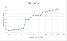
In fluid dynamics, the drag coefficient (CD) is a dimensionlessquantitythatisusedtoquantifythedragor resistanceofanobjectinafluidenvironment,suchasairor water. The plot of drag coefficient versus Angle of attack overGottingen526Airfoilisshowninfigurebelow.
from bubble columns to oil platforms, from blood flow to semiconductormanufacturing.Inthispaper,Ansys Fluent hasbeenusedtoanalyzetheliftanddragcoefficientsforthe aircraftwing.TheInputconditionsusedfortheCFDanalysis aregivenbelow.
Model :Viscous Spalart Allmaras(1eqn) Material :Fluid Density :IdealGas
Viscosity :Sutherland Operatingcondition : 0pa(Operatingpressure)
Boundaryconditions :WallsandPressurefarfield
Machnumber :0.05
U velocity :0.912545
V Velocity :0.406736 Temperature :300K
ContourPlots:
Generating mesh is neither easy nor fun. But mesh generationiswhereyouhavethemostdirectinfluenceon how fast, how converged and how accurate your CFD solutions is. Because of that you need a mesher that is flexible and reliable and so the Gridgen tool is used. The details of the mesh generated over the wing are given in figurebelow.
TypeofGrid :Multiblockstructuredgrid
TotalNumberofgrid :14340
Celltype :Quadrilateralelement
NumberofElement :13924
Numberofblocks :3blocks

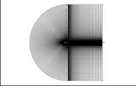
Boundaryconditions :WallandPressurefarfield
Pressurecanbeusedtocalculateforcessuchaslift,dragor torqueonobjectsintegratingthepressureoverthesurface oftheobject.
ANSYS FLUENT contains the broad physical modeling capabilitiesneededtomodelflow,heattransfer,turbulence and reactions for industrial applications ranging from airflow over an aircraft wing to combustion in a furnace,
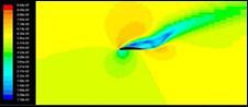
Theabovefigureshowsthepressuredistributionoverthe wingat24˚Angleofattack.Thepressureatthebottomofthe airfoilishigherthantheupperairfoil
A method of measuring stream discharge in which point velocity measurements are translated into average cross sectionalflowvelocitiesbycontouringthepointvelocities.
International Research Journal of Engineering and Technology (IRJET) e ISSN: 2395 0056
TheabovefigureshowsthecontoursofMachnumberover thewing.TheMachcontourplotrevealshighvelocityatthe uppersurfaceandlowvelocityatthebottomsurfaceofthe wing.
Thetypeoftailsectionusedinthispaperisconventionaltail. Thisconfigurationincludesonehorizontaltail(twoleftand right section); located on the tail of the fuselage and one vertical tail (one section) located on top of the tail of fuselage.Bothverticalandhorizontaltailsarelocatedand mountedtothetailoffuselage.
The design of horizontal stabilizer had been made by calculatingthefollowingparameters.
5.1.1
Stabilizerareashouldbearound14to15percentageof thewingarea.
WingArea=605cm^2 15%ofwingarea=0.15*605TailArea(St)=90.75cm^2
5.1.2 Tail span (bt)
Tailspan(bt)=(ARt*St)^1/2Where, ARt=AspectRatioofTailshouldbelessthanWing=4. TailSpan(bt)=19.05cm
5.1.3 Tapper ratio (TRt)
Tapperratioofthetail=0.66(assumed)
5.1.4
Tail root chord (Croo t)
Tailrootchord=2*St/(bt(1+TRt))=2*90.75/ (19.05(1+0.66)
=181.5/31.54
TailRootChord(Croott)=5.75cm
5.1.5
Tail tip chord
TipChord(Ctip)=(TRt*Croot) =(0.66*5.75) =3.75cm
Tailangleshouldbe1to1.5degreeslessthanα.
α=3degree(wing) αt=2degree(Tail)
Thedesignofverticalstabilizerhadbeenmadeby calculatingthefollowingparameters
5.1.1 Chord tip
ChordTip(Ctip)=1*D Where, D=FuselageHeight(6.2cm)
Ctip=6.2cm
5.1.2 Root chord
RootChord(Croot)=2*DCroot=12.4cm Span=2*DSpan=12.4cm
The electrical components used for fabricating the RC poweredaircraftarelistedbelow,
BrushlessMotor :1600kv Servo(4Nos) :180degree
ESC :ElectronicSpeedControl
LIPOBattery :11.1V
FlySkyTransmitter :2.4GHZ
FlySkyReceiver :2.4GHZ
Volume: 09 Issue: 07 | July 2022 www.irjet.net p ISSN: 2395 0072 © 2022, IRJET | Impact Factor value: 7.529 | ISO 9001:2008 Certified Journal
International Research Journal of Engineering and Technology (IRJET) e ISSN: 2395 0056
Volume: 09 Issue: 07 | July 2022 www.irjet.net p ISSN: 2395 0072
Thesecomponentsarereadilyavailableinmarketsandneed nottobeprogrammedbytheuser.
The fuselage construction consists of Front section, Mid sectionandAftsection.
FrontSection:
FromthebasicconfigurationofRCPlane,thefrontsection shouldbe1.3ofchordlengthandsothefrontsectionlength willbe14.3cm.
Mid Section: Thissectionisforplacingthewingthatis11cmchord length.
AftSection: Thissectionshouldbe2.4ofchordlength,i.e.is26.4cm.
Landinggearisthe undercarriage of an aircraft, maybe used for either landing or take off. It absorbs the landing shocks,dampenthevibrationetc.ThetypeofLandinggear usedinthispaperisTailDraggerwhichisfabricatedusing aluminumsheet.
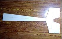
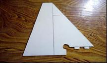
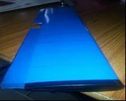
Based upon the above calculations, wing section, fuselage section, tail section was fabricated using foam material as sowninfigurebelow.
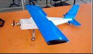
Figure 12: RC Aircraft model
FromtheabovemethodologyandconceptstheRCpowered Aircraft wing had been designed and tested both experimentally and computationally. The results of both tests were compared. And also the wing is placed in the workingmodelandwassuccessfullyflown.Theapplications ofRCPlanewerestudied.
[1] KrishnanR,NarayananChavan,SandeepNayak,Shryas S Hedge, “A Systematic Approach for Designing, Analysing and Building a Model RC Plane,” December 2014
[2] Mahesh Pula, Omkar Bhosle, Rohit Varpe, “Radio ControlledAirplane,”Febraury2015
[3] Nguyen Minh Triet, Nguyen Ngoc Vipt, Pham Manh Thang,“AerodynamicAnalysisofAircraftWing,”January 2015
[4] 4. Pradyumna SV, Prateek R, Raju BS, “Design and FabricationandAnalysisofaHighwingerConventional TailRadioControlledAirplane,”July2015
[5] 5. Rochen Krishna TS, Shankar goud Nyamannavar, SharathRao,ShreyKrishnamoorthy,SurajJeyashankar, “CFDAnalysisofanAircraftWing,”September2014
Figure 11: Wing construction