International Research Journal of Engineering and Technology (IRJET) e ISSN: 2395 0056

Volume: 09 Issue: 07 | July 2022 www.irjet.net p ISSN: 2395 0072
International Research Journal of Engineering and Technology (IRJET) e ISSN: 2395 0056
Volume: 09 Issue: 07 | July 2022 www.irjet.net p ISSN: 2395 0072
1 M.Tech scholar, Electrical Department, RSR Bhilai, Chhattisgarh, India 2Assistant Professor, Electrical Department, RSR, Bhilai, Chhattisgarh, India 3 Assistant Professor, Electrical department, RSR Bhilai, Chhattisgarh, India ***
Abstract The isolated DC microgrid is independent from the power grid. It consists of distributed energy sources (DER) in the form of solar photovoltaic (PV) panels, as well as batteries and connected loads. The goal of this concept is to meet the growing demand for energy. Until now, countries like India have used conventional energy sources, which are in limited supply. To balance the growing demand for energy, the best way is to switch to renewable sources for energy production. Also in dark areas where it is almost impossible to transport electricity, this concept of an isolated DC microgrid can be implemented to electrify remote areas. Another advantage is that; earn carbon credits. The whole system includes a photovoltaic generator, an MPPT (Maximum Power Point Tracking) algorithm and a battery to maintain the voltage level because the nature of solar energy is intermittent as the glare from the sun fluctuates each time. This is achieved using the MPPT charge controller. The electronically operated DC DC converter is MPPT, which stands for Maximum Power Point Tracking. MPPT controller improves solar and battery power. It also protects the battery from overcharging, thus protecting the battery. The voltage obtained from MPPT is DC voltage and is used for the operation of the AC charging inverter circuit. This article presents an MPPT design using the observation and disturbance method.
Key Words: PV solar array, Battery, Load, MPPT charge controller, Arduino.
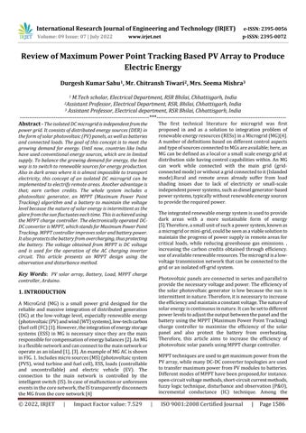
A MicroGrid (MG) is a small power grid designed for the reliable and massive integration of distributed generation (DG)atthelow voltagelevel,especiallyrenewableenergy (photovoltaic(PV)andwind(WT)systems),low techcarbon (fuelcell(FC)[1].However,theintegrationofenergystorage systems (ESS) in MG is necessary since they are the main responsibleforcompensationofenergybalances[2].AnMG isaflexiblenetworkandcanconnecttothemainnetworkor operateasanisland[1],[3].AnexampleofMGACisshown inFIG.1.Includesmicrosources(MS)(photovoltaicsystem (PVS),windturbineandfuelcell),ESS,loads(controllable and uncontrollable) and electric vehicle (EV). The connection to the main network is controlled by the intelligentswitch(IS).Incaseofmalfunctionorunforeseen eventsinthecorenetwork,theIStransparentlydisconnects theMGfromthecorenetwork[4]
The first technical literature for microgrid was first proposed in and as a solution to integration problem of renewableenergyresources(RESs)inaMicrogrid(MG)[4]. Anumberofdefinitionsbasedondifferentcontrolaspects andtypeofsourcesconnectedtoMGsareavailable;here,an MGcanbedefinedasalocalorasmallscaleenergygridat distributionsidehavingcontrolcapabilitieswithin.AnMG can work while connected with the main grid (grid connectedmode)orwithoutagridconnectedtoit(Islanded mode).Rural and remote areas already suffer from load shading issues due to lack of electricity or small scale independentpowersystems,suchasdieselgenerator based powersystems,typicallywithoutrenewableenergysources toprovidetherequiredpower.
Theintegratedrenewableenergysystemisusedtoprovide dark areas with a more sustainable form of energy [5].Therefore,asmallunitofsuchapowersystem,knownas amicrogridormini grid,couldbeseenasaviablesolutionto maintaintheprogressofpowersupplyinremoteareasfor critical loads, while reducing greenhouse gas emissions. , increasing the carbon credits obtained through efficiency. useofavailablerenewableresources.Themicrogridisalow voltagetransmissionnetworkthatcanbeconnectedtothe gridoranisolatedoff gridsystem.
Photovoltaicpanelsareconnectedinseriesandparallelto providethenecessaryvoltageandpower.Theefficiencyof the solar photovoltaic generator is low because the sun is intermittentinnature.Therefore,itisnecessarytoincrease theefficiencyandmaintainaconstantvoltage.Thenatureof solarenergyiscontinuousinnature.Itcanbesettodifferent powerlevelstoadjusttheoutputbetweenthepanelandthe batteryusingtheMPPT(MaximumPowerPointTracking) charge controller to maximize the efficiency of the solar panel and also protect the battery from overheating. Therefore, this article aims to increase the efficiency of photovoltaicsolarpanelsusingMPPTchargecontroller.
MPPTtechniquesareusedtogetmaximumpowerfromthe PVarray,whilemanyDC DCconvertertopologiesareused totransfermaximumpowerfromPVmodulestobatteries. DifferentmodesofMPPThavebeenproposed,forinstance. open circuitvoltagemethods,short circuitcurrentmethods, fuzzylogictechnique,disturbanceandobservation(P&O), incremental conductance (IC) technique. Among the
International Research Journal of Engineering and Technology (IRJET) e ISSN: 2395 0056
Volume: 09 Issue: 07 | July 2022 www.irjet.net p ISSN: 2395 0072
different MPPT modes, the Perturbation and Observation (P&O)techniqueproducesexcellentresultsandisrelatively easy to implement and use [6]. This work consists of the design of the MPPT charge controller using a DC DC step downconverter.Theconverteriscontrolledbyarduino.
Figure1:ExampleofanACmicrogrid
All tropical countries are endowed with good natural resources. Solar power, wind power, tidal power, hydropoweraresomeexamples.
AsforIndia,ithas34solarparksin24stateswhoseenergy canbeusedinmanyfields,suchasagriculture,forindustrial purposes, or for some household appliances separately in ruralorurbanareas.Italsoholdstherecordfortheworld's largestrooftopsolarinstallationof12.5MWinPunjab[7]. The other sources such as wind power, tidal power and hydroelectric power are widely used in some parts of the country.
Considering India, it has 34 solar parks in 24 states, the energyofwhichcanbeusedeverywhereinmanyfieldslike inagriculture,forindustrialuseorforsomehomeappliances separatelyinruralorurbanareas[8].Italsoheldrecordof world’s largest solar roof top installation of 12.5MW in Punjab [9]. The other resources like wind energy, tidal energy,hydropowerenergyarewidelyusedinsomeofthe country.
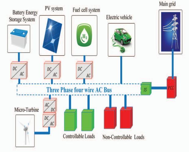
The solar model consists of many photovoltaic cells in parallelandseriesconnectionandthisentirerepresentation constitutesthePVarray[10].ThePNjunctionisformedby thesecellsmadeupofsiliconcrystals,therebyformingthe semiconductor wherein the electrons move freely to combine with the holes to form electron hole pairs. This process of electron hole pair generation leads to the formationofdepletionregion(alsoknownasspacecharge region)whichisdeprivedofanychargecarriers.
Photovoltaiccellsandpanelsconvertthesolarenergyinto direct current(DC)electricity.Theconnectionofthesolar panelsinasinglephotovoltaicarrayissameasthatofthePV cellsinasinglepanel.
Thepanelsinanarraycanbeelectricallyconnectedtogether in either a series, a parallel, or a mixture of the two, but generallyaseriesconnectionischosentogiveanincreased outputvoltage[11].Forexample,whentwosolarpanelsare wiredtogetherinseries,theirvoltageisdoubledwhilethe currentremainsthesame.
The size of a photovoltaic array can consist of a few individual PVmodulesorpanelsconnectedtogetherinan urban environment and mounted on a rooftop, or may consist of many hundreds of PV panels interconnected together in a field to supply power for a whole town or neighborhood [12]. The flexibility of the modular photovoltaicarray(PV system)allowsdesigners tocreate solar power systems that can meet a wide variety of electricalneeds,nomatterhowlargeorsmall.
Itisimportanttonotethatphotovoltaicpanelsormodules fromdifferentmanufacturersshouldnotbemixedtogether in a single array, even if their power, voltage or current outputs are nominally similar [13]. This is because differencesinthesolarcellI Vcharacteristiccurvesaswell as their spectral response are likely to cause additional mismatch losses within the array, thereby reducing its overallefficiency.
AnMPPT,ormaximumpowerpointtrackerisanelectronic DCtoDCconverterthatoptimizesthematch betweenthe solararray(PVpanels),andthebatterybankorutilitygrid. To put it simply, they convert a higher voltage DC output fromsolarpanels(andafewwindgenerators)downtothe lowervoltageneededtochargebatteries
Maximum Power Point Tracking is electronic tracking usuallydigital.Thechargecontrollerlooksattheoutputof the panels and compares it to the battery voltage. It then figuresoutwhatisthebestpowerthatthepanelcanputout
2022, IRJET | Impact Factor value: 7.529 | ISO 9001:2008 Certified Journal |
International Research Journal of Engineering and Technology (IRJET) e ISSN: 2395 0056
Volume: 09 Issue: 07 | July 2022 www.irjet.net p ISSN: 2395 0072
to charge the battery. It takes this and converts it to best voltagetogetmaximumAMPSintothebattery.(Remember, itisAmpsintothebatterythatcounts).MostmodernMPPT's arearound93 97%efficientintheconversion.Youtypically get a 20 to 45% power gain in winter and 10 15% in summer. Actual gain can vary widely depending weather, temperature,batterystateofcharge,andotherfactors.
MPPT serves the purpose of tracking the solar energy to achievemaximumpowerfromthePVsystem.Thevarious typesofMPPTarelistedbelow[5]: 1) PerturbandObserve 2) Incrementalconductance 3) Fractionalshortcircuitcurrent 4) Fractionalopencircuitvoltage 5) FuzzyLogic 6)
NeutralNetwork
Aspecificalgorithmtobeuseddependsuponthenatureof complexityandtimetakentotrackthemaximumpower.In this representation, perturb and observe method is used usingMATLAB/Simulink[14].
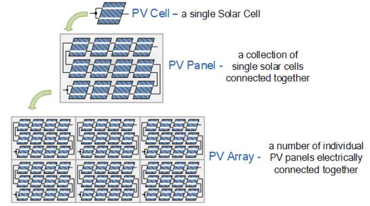
In this technique, as the name suggests, perturbation and observationisdonetogettheMPP.Aperturbationisdoneto vary the output power of the PV module by periodically measuringitandcomparingwiththepreviouspower.Ifthe outputdecreases,thentheperturbationisreversedorelse thesameprocessisrepeated.Ifthepowerisincreaseddue to increase in voltage, the operating point is on the left of MaximumPowerPointandthus,thePVmodulewillperform further perturbations on the right to reach the MPP. Contrarily, if the power is decreased due to increase in voltage,theoperatingpointisontherightoftheMaximum PowerPointandthus,perturbationswillbeperformedon the left to reach the MPP [15, 16]. The process flow chart adopted is shown in the figure below. The MPPT charge controller linked between the PV module and the battery playsanimportantroleofmeasuringthearrayandbattery voltages. It also detects when the battery is completely chargedandprotectsitfromovercharging[17,18].
Similarly, when the battery is not charged completely, it activatestheconvertercircuittochargethebattery.Thenew power, P(new) is measured by the microcontroller and compares it with the previous power P(old). If P(new) is greaterthanP(old),thenthemaximumpowerisextracted from the PV panel by increasing the PWM duty cycle. Conversely, when the P(new) is less than P(old), then the system is moved back to the previous maximum limit by decreasingthedutycycle.Hence,thismethodissimple to effectuatewithverylittlecomplexitiesandwithlowcost[19, 20].
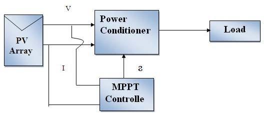
TheloadandPVarraywillinterfacewitheachotherifthere istunablematchingnetworkpresentbeetweenthemthen mpptoperateaccurately.Aswecanseeinfig.3beloware themainportionsofPVcellarepowerstageandcontroller. ForswitchingonpowerstageDCtoDCconverterareused. InthiscaseweareusingBuckconverterwhichisconnected toPVarrayforemployingPWMcontrol.
For maximum exactraction of power from PV array the control parameter is duty ratio which is δ, utilized for tunningofthenetwork.
Fig.3.MPPTwithPVsystem.
The characteristic graphs of MPPT and PV array are shown in below fig.4. Which give us the maximum operatingpointinboththecases,likeinP VcurveandI V curve.
There are varies method of MPPT techniques listed below. The necessity of MPPT used here is dealing with volatge parameter, absence of periodic tunning, easy in implementation and should have instant changing convergence speed . These all conditions are fulfiiled by PerturbandObservemethodfromallMPPTtechniques.
2022, IRJET | Impact Factor value: 7.529 | ISO 9001:2008 Certified
International Research Journal of Engineering and Technology (IRJET) e ISSN: 2395 0056
Volume: 09 Issue: 07 | July 2022 www.irjet.net p ISSN: 2395 0072
MPPT Techniques Convergen cespeed Implementa tion complexity
Perturb
Periodic tunning Sensed Para meters
merchandise of the change duty cycle and therefore the provide voltage [22]. The dc to dc device is employed to stepdownthe18voltsobtainedfromthePVarrayto12 voltswhichfitstotheresistancescircuit[24,25].
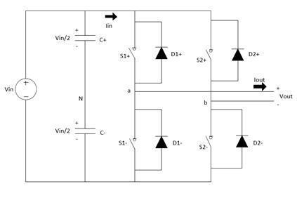
Inverter is a basically a device that converter the electricityderivedfromaDCsourcetoACsource[28].The converter is totally based on the application. In a solar energy system, as an example, the ability hold on by batteries charged by star panels is born again to straightforwardACpowerbytheelectricalconverter,that providestheabilitytoplug inshopsandalternativenormal 120volts[24].
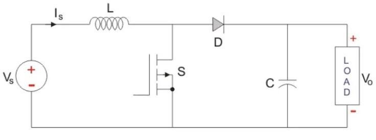
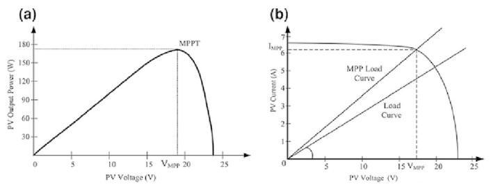
Figure4:InterfacinggraphofPVandMPPT.
DC DCconvertersarealsoknownasChoppers.Here we will have a look at the Step Up Chopper or Boost converter which increases the input DC voltage to a specified DC output voltage. A typical Boost converter is shownbelow.
Thebuckdevicecouldbeaterriblystraightforward styleofDCtoDCconverterthatproducesanoutputvoltage that’s but its input . The buck device, because the name suggests “bucks” or acts against the input voltage. The outputvoltageofaperfectbuckdeviceisadequatetothe
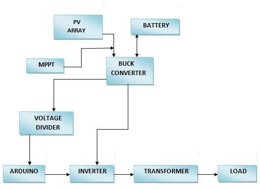
Intheisolateddcmicrogridtheworkingistotallybasedon theblockwhichwehavestudiedabove.Whensunrays of thesunhitsonthesolarpanelthentheMPPTgetsactivated andcollectthegoodamountofenergycomingfromsun.The MPPT will send this charge to the voltage divider for steppingdownthevoltage,asarduinorequirevoltageonly upto5Vandtheoutputvoltagegettingfromthesolaris18V. TheseallratingaredisplayedontheLDCdisplay.Theoutput from the arduino is given to the inverter and then to the transformerandfinallytoload.Thisprocesstakesplaceat thedaytime.Atnight,thevoltageremainsafterdividingthe voltage is get stored in the battery which is connected to MMPTdevice.Soatthedaytimebatterygetchargedform the sun and stored energy, and the night when no sun availablethechargedbatterycanbeusedfromtheconsumer [3].Thisismethodtogenerateaseparateandindependent sourceofelectricitytotheremoteparts.
International Research Journal of Engineering and Technology (IRJET) e ISSN: 2395 0056
Volume: 09 Issue: 07 | July 2022 www.irjet.net p ISSN: 2395 0072
[1] S. Dhar, R Sridhar and V. Ava, “Modeling and SimulationofPhotovoltaicArrays,”unpublished.
[2] Z.FushengandR.Naayagi,“Powerconvertersfordc microgrid modelling and simulation,” IEEE 2018 (ISGTAsia).
[3] C.Phurailatpam,R.Sangral,B.Rajpurohit,F.longatt and S. singh, “Design and analysis of a dc microgrid withcentralixedbatteryenergystoragesystem,”IEEE Conference(INDICON2015),2015.
As the concept is completely based on renewable sourceofenergyi.e.solarenergy,thisideacanbeextended at a great level in future. Taking as an example, India receivesallover5000trillionkWhofpuresolarenergyeach year which is excessively more than the electricity consumption of the country. The geographical location of Indiawillhelptoimplementmoresuchprojectsbasedonthe renewable source of energy. It will help diminish the problems of frequent power outages and discontinuity of supply.Itisalsoreliableandhascostbenefits.Thecostwill mainlybedependentonthedevelopmentandinstallation, storageofenergyaswellasontheautomationofgrid.The barriers to overcome are monitoring and control, storage and alternative generation source, cost collection, site identification,changingweather,etc.
In rainy season the irradiation of solar would fluctuated, which may affect the efficiency of MPPToutput.
[4] U. patel, Ms. D. sahu, and D.Tirke, “Maximum power point tracking using perturb and observe algorithm and compare with another algorithm,” International Journal of digital application & contemporary, September2013.
[5] R.kumar,A.Choudhary,G.Koundal,A.yadav,andA. singh,“Modellingorsimulationofmppttechniquesfor photovolataic system using matlab,” International journalofadvancedresearchincomputerscienceand softwareengg,april2017.
[6] S.jainandV.Agarwal,“Comparisonoftheperformance ofmaximumpowerpointtrackingschemesappliedto single stage grid connected photovolataic sysytem,” IETelectr.Powerappl.,2007.
[7] Prof.RajeevValunjkar,VimithShetty,MihirPathare, AniketSawantandDiptarkaDatta,“DesigningofMPPT SolarChargeControllerusingProteus,”unpublished.
[8] ForumofRegulators,“Reportonmeteringregulation andaccountingframeworkforgridconnectedrooftop solarPVinindia”AReport.
[9] Articaleofsolarenergycooperationindialimited.
EvenafterachievingtheMPP,thesystemwill stillperformperturbationstoachieveanother maximumpoint.
[10] Yejee Choi, Monineath Khun and Giselle Verbera, “MaximumPowerPointTrackingproject,”Areport.
Inacircumstancewheretheirradiancechanges rapidly,theMPPlikewiseproceedonwardthe correcthandsideofthebend[4].
Since,majorpartsofIndiahavenotbeenelectrifiedyet,this project will provide with an alternate solution to use electricitywithoutanyinterruptions.Theimplementationis simpleandhence,easeofuseiscollateral.
Thecoordinationofvariouscomponentsusedenableshigh efficiency and a sense of getting electricity independently andusingitjudiciously.
[11] F.Z. Aziz and N. Mohd Yunus, “Photovoltaic array modellingwithP&Omethodinmatlab,”unpublished.
[12] J.GowandC.Manning,“Developmentofphotovoltaic arraymodel forused inpowerelectronic simulation studies,”IEEproceedingelectricapplication,1999.
[13] HyeonahParkandHyosungKim,“PVcellmodelingon single diodeequivalentcircuit,” IEEE2013
[14] A. Bilsalam, V. Chunkag, I. Boonyaroonate, and J. Sharma, “Simulation and study of photovolataic cell power output characteristics with buck converter load,”conferencerecordonICPE.
International Research Journal of Engineering and Technology (IRJET) e ISSN: 2395 0056
Volume: 09 Issue: 07 | July 2022 www.irjet.net p ISSN: 2395 0072
[15] Varshney,M.DaveandD.chauhan,“Simpscapebased modelling & simulation of mppt controller for PV system,”(IOSR JEEE),nov dec2014
[16] A. Mohapatra, Byamakesh Nayak and K. Mohanty, “CurrentbasednoveladaptiveP&Ompptalgorithmfor photovolataic system considering sudden change in theirradiance,”IEEE(PEDES)2014.
[17] T. Estamos and P. Chapman, “ Comparison of photovolataic array maximum power point tracking techniques,” IEEE transaction on energy conversion, june2007.
[18] N. Femina, G. Petrine, Giovanni Spagnuolo and M. Vitelli, “ Optimization of perturb and observe maximumpowerpointtrackingmethod,”International conference on recent trend in applied science with engg.Application4,July2005.
[19] D. Sharma, G. Purohit, “ Advanced perturbation and observationbasedmaximumpowerpointtrackingof solarphotovolataicsystem,”IEEE2012.
[20] G.Petrone,N.Femina,G.Spagnuolo,“optimozationof perturbandobservemaximumpowerpointtracking method,”IEEE2005.
[21] M.G.Villalva,J.Gazoli,ErnestoR.Filho,“Analysisand simulationofthep&ompptalgorithmusingalinearized PV array model,” IECON2009 conference of IEEE , 2009.
[22] K.Yao,“Anovel windingcoupledbuck converterfor highfrequency,highstepdowndctodcconversion,” IEEEtransactiononpowerelectronic,2005.
[23] S.Soheli,DrG.sarowar,andprof.Md.ashrafulHowie, “Designandanalysisofdctodcbuckboostconverterto achievehighefficiencyandlowvoltagegainbyusing buck boost topology,” International conference on advancement in electrical and electronic engg. Nov 2018.
[24] P.SBhimbra,KhannaPublishers,“PowerElectronics,” ABook.
[25] D.chaudharyandA.Saxena,“dctodcbuckconverter formpptofPVsystem,”InternationalJournalofengg. Technologyandadvancementengg.,July2014.
2022, IRJET | Impact Factor value: 7.529 | ISO 9001:2008 Certified Journal