International Research Journal of Engineering and Technology (IRJET) e-ISSN: 2395-0056

Volume: 09 Issue: 07 | July 2022 www.irjet.net p ISSN: 2395 0072
International Research Journal of Engineering and Technology (IRJET) e-ISSN: 2395-0056
Volume: 09 Issue: 07 | July 2022 www.irjet.net p ISSN: 2395 0072
123U.G Students, Dept. of Mechanical Engineering, RGUKT, Srikakulam, Andhra Pradesh, India. Asst. Professor, Dept. of Mechanical Engineering, RGUKT, Srikakulam, Andhra Pradesh, India. ***
ABSTRACT: This is an idea of integrating both the units, water chiller and air cooler by considering the power consumption and their individual cost. Water Chillers and Air Coolers has become a need for every individual. By recognising the demand, a new unit in their combination is designed. Both the units work on single compressors. A T Joint is attached containing a split valve to divide the refrigerant to both the units. An Arduino code driven servo motor is used to control the flow of the refrigerant through the valve. Computational Fluid Dynamics were carried to check the pressure drop in T Joint. Design and modelling of the geometry was prepared in SOLIDWORKS and the analysis of the T Joint in ANSYS 2021R2.
Key words: WaterChiller,AirCooler,SplitValve,Refrigerant,Arduino.
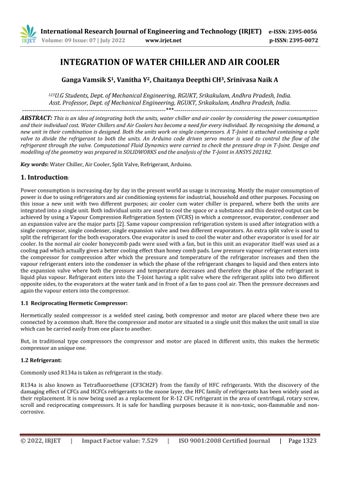
Powerconsumptionisincreasingdaybydayinthepresentworldasusageisincreasing.Mostlythemajorconsumptionof powerisduetousingrefrigeratorsandairconditioningsystemsforindustrial,householdandotherpurposes.Focusingon this issue a new unit with two different purposes; air cooler cum water chiller is prepared, where both the units are integratedintoasingleunit.Bothindividualunitsareusedtocoolthespaceorasubstanceandthisdesiredoutputcanbe achievedbyusingaVapourCompressionRefrigerationSystem(VCRS)inwhichacompressor,evaporator,condenserand anexpansionvalvearethemajorparts[2].Samevapourcompressionrefrigerationsystemisusedafterintegrationwitha singlecompressor,singlecondenser,singleexpansionvalveandtwodifferentevaporators.Anextrasplitvalveisusedto splittherefrigerantforthebothevaporators.Oneevaporatorisusedtocoolthewaterandotherevaporatorisusedforair cooler.Inthenormalaircoolerhoneycombpads wereusedwithafan,butinthis unitanevaporatoritselfwasusedasa coolingpadwhichactuallygivesabettercoolingeffectthanhoneycombpads.Lowpressurevapourrefrigerantentersinto the compressor for compression after which the pressure and temperature of the refrigerator increases and then the vapourrefrigerantentersintothecondenserinwhichthephaseoftherefrigerant changestoliquidandthenentersinto the expansion valve where both the pressure and temperature decreases and therefore the phase of the refrigerant is liquid plus vapour. Refrigerant enters into the T Joint having a split valve where the refrigerant splits into two different oppositesides,totheevaporatorsatthewatertankandinfrontofafantopasscoolair.Thenthepressuredecreasesand againthevapourentersintothecompressor.
Hermetically sealed compressor is a welded steel casing, both compressor and motor are placed where these two are connectedbyacommonshaft.Herethecompressorandmotoraresituatedinasingleunitthismakestheunitsmallinsize whichcanbecarriedeasilyfromoneplacetoanother.
But, in traditional type compressors the compressor and motor are placed in different units, this makes the hermetic compressoranuniqueone.
CommonlyusedR134aistakenasrefrigerantinthestudy.
R134a is also known as Tetrafluoroethene (CF3CH2F) from the family of HFC refrigerants. With the discovery of the damagingeffectofCFCsandHCFCsrefrigerantstotheozonelayer,theHFCfamilyofrefrigerantshasbeenwidelyusedas theirreplacement.ItisnowbeingusedasareplacementforR 12CFCrefrigerantintheareaofcentrifugal,rotaryscrew, scroll and reciprocating compressors. It is safe for handling purposes because it is non toxic, non flammable and non corrosive.
International Research Journal of Engineering and Technology (IRJET) e-ISSN: 2395-0056
Volume: 09 Issue: 07 | July 2022 www.irjet.net p ISSN: 2395 0072
ThesplitvalvefitsinanewlydesignedT Jointwhichisusedtobisecttherefrigeranttotwodistinctunits.Thevalveinside is water tight and connected to the servo motor from outside. The servo gets inputs from Arduino uno and rotates accordingly.Throughthis,asignificantflowisachievedasperrequirement.
Assembly for unification of both units was inspired from a refrigerator tank at our university. The complete design was made into two parts; outdoor unit and indoor unit. Indoor unit consists of an air cooler and water chiller with an expansion valve whereas the outdoor unit consists of a compressor, condenser and a fan, to pass out the heat from the condenser.Theoutdoorunitisattachedtothelowersideofthemainunit.AnewlydesignedT Jointisusedtouniteboth theevaporatorsasshown inschematic diagramoffig 1.AT Jointisaddedbetweenexpansionvalveand evaporators,so thatrefrigerantcanbemanagedtoflowintotwoseparateevaporators atatime.Therefrigerantgetssplitintotwopaths and enters into the evaporators of both the water chiller and the air cooler. The temperature limits are monitored and maintainedbyatemperaturesensor.
Fig 1: SolidmodellingofIndoorunitandOutdoorunit;Theschematicdiagramoftheentireunitafterintegration.
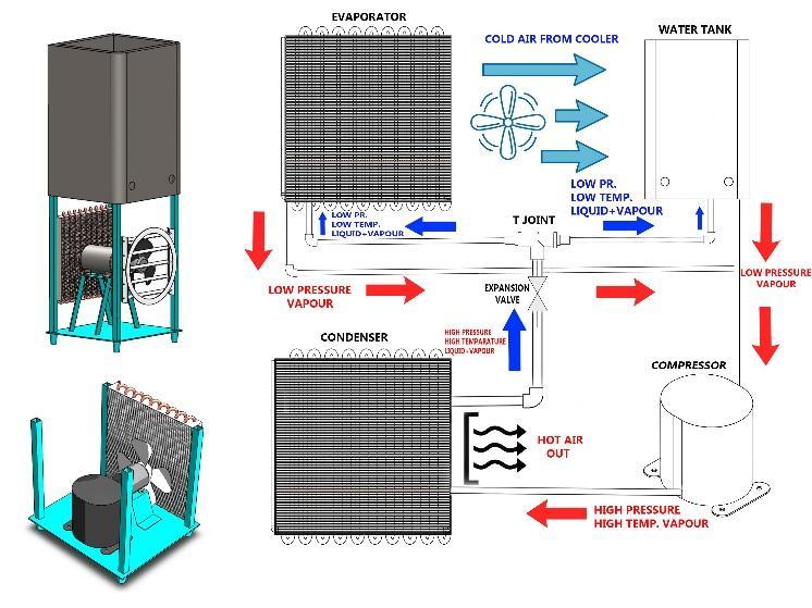
The T Joint with three openings, which is used to integrate two units is designed in Solidworks and imported to Ansys Workbenchin‘.STEP’or‘.IGS’formatforfluidanalysis.
Fig 2: CrosssectionviewofT Jointwithsplitvalveatcentreposition.
International Research Journal of Engineering and Technology (IRJET) e-ISSN: 2395-0056
Volume: 09 Issue: 07 | July 2022 www.irjet.net p ISSN: 2395 0072
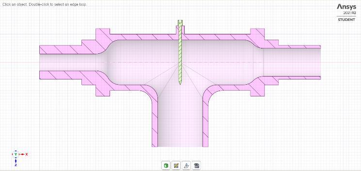
3.2 3D Meshing: Meshforthegeometryasinfig 2wasgeneratedinAnsysFluent.Inflationwasaddedonthewallsidetocontroltheshear force.NamedSelectionswereaddedtotheT Jointas‘inlet’and‘outlet’atrespectiveinletandoutlets Fig 3: 3DunstructuredtetrahedralmeshofT Joint 3.3
International Research Journal of Engineering and Technology (IRJET) e-ISSN: 2395-0056 Volume: 09 Issue: 07 | July 2022 www.irjet.net p ISSN: 2395 0072
Area=1m2
Density=1305.8kg/m3 Enthalpy=0J/kg Length=1m Pressure=0Pascal Temperature=288.16K Velocity=19.22517m/s Viscosity=0.000254kg/m s RatioofSpecificHeats=1.4
International Research Journal of Engineering and Technology (IRJET) e-ISSN: 2395-0056
Volume: 09 Issue: 07 | July 2022 www.irjet.net p ISSN: 2395 0072
Computefrom Inlet ReferenceFrame
InitialValues
INITIALIZE
Run Calculation
RelativetoCellZone
ZVelocity= 19.22517m/s
GaugePressure=0Pascal
Numberofiteration 100
ReportingInterval 1
ProfileupdateInterval 1
Valve moment inside T Joint:
Thethreeoperatingconditionsare:
1. Refrigerantflowtobothunits
2. RefrigerantflowonlytoAirCooler
3. RefrigerantflowonlytoWaterChiller
SplitValveiscontrolledusinganArduinomodulethatoperatesoninputsreceivedthroughtemperaturesensors.Aservo motorisconnectedtothevalveandthemomentisgovernedbyArduinocodesatrequiredthreeconditions.Initiallywhen bothunitsareinswitchonmode,thevalvewillbeinzerodegrees,whichmeansthesameamountofflowtoboththeunits. Afteracertaintime,whenthewatertankattainsacertaintemperaturei.e10degreecelsius,thenthroughsensors,inputs aresenttotheArduinoandthevalvestartsfunctioning.Bythe arduinocode,thesplitvalvemoves45degreesclockwise, sothatthemaximumamountofrefrigerantwillflowtotheaircooler.Andwhenthetemperaturein thewatertankdrops belowthesetuplevel,thevalvecomesbacktoitsinitialpositionaszerodegrees.Attimes,wedonotrequireanaircooler, then an arduino connected controlled switch rotates the split valve by 45 degrees anti clockwise and allows maximum flowtothewaterchilleronly.Withthethreedifferentdirectionsofsplitvalve,AirCoolerandWaterChillerareintegrated
Afterthesetupandprocessingthesolution,resultsareanalysed.Inthethreedifferent operatingconditions,thepressure andvelocityofrefrigerantaredifferent,whicharecrucialtomonitortoavoidvalvedamage.Thesimulationsetupissame ateveryconditionanditonlydiffersintheamountofrefrigerantflow.
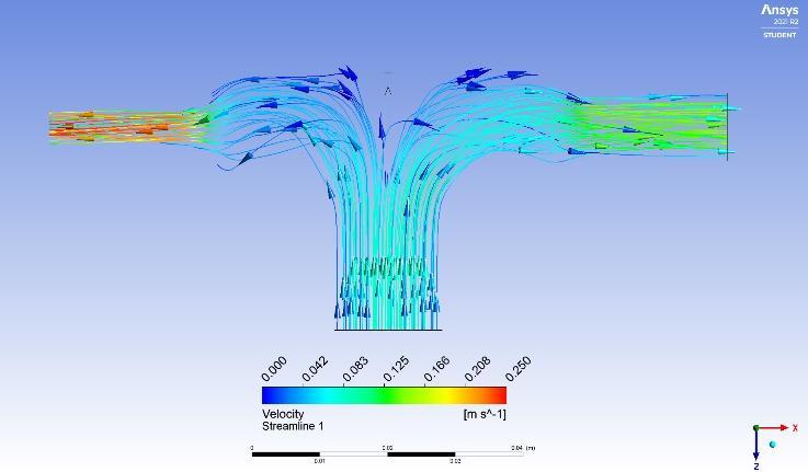
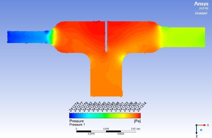
However,thefluidbehaviourinsideT Jointisstudiedandtheanalysiswerecarriedoutatagiveninputpressureandmass flowoutlet.Thepressurecontourandvelocityflowweredisplayedasinfig 4andfig 5respectively.
The refrigerant must flow to both the units through the valve. At this condition the valve must be in centre to allow the flowtoboththeunits.Generallythisconditionoccursattheinitialstartofthewholeunit.
International Research Journal of Engineering and Technology (IRJET) e-ISSN: 2395-0056
Volume: 09 Issue: 07 | July 2022 www.irjet.net p ISSN: 2395 0072
Fig-4: PressurecontourofrefrigerantinsideT Joint.
Fig 5: VelocitystreamlineoffluidinsideT Joint. Sample arduino code for valve movement: #include<Servo.h> Servomyservo; //createservoobjecttocontrolaservo intpos=0; //variabletostoretheservoposition voidsetup(){ myservo.attach(9); //attachestheservoonpin9totheservoobject pinMode(5,INPUT);//forgettingtemperatureasinput pinMode(6,INPUT);//forgettinginputfromswitch pinMode(7,INPUT);//forgettinginputfromswitch } voidloop(){ for(pos=0;pos<=45;pos+=1){//goesfrom0degreesto45degrees //instepsof1degree myservo.write(pos); //tellservotogotopositioninvariable'pos'
International Research Journal of Engineering and Technology (IRJET) e-ISSN: 2395-0056
Volume: 09 Issue: 07 | July 2022 www.irjet.net p ISSN: 2395 0072
if(digitalRead(5)==12)//ifthetemperatureis12degrees { delay(15); //waits15msfortheservotoreachtheposition } } if(digitalRead(6)==HIGH)//ifswitchison { for(pos=0;pos<=45;pos =1){//goesfrom180degreesto0degrees myservo.write(pos); //tellservotogotopositioninvariable'pos' delay(15); //waits15msfortheservotoreachtheposition } } if(digitalRead(7)==HIGH)//ifanotherswitchison { for(pos=0;pos<=45;pos+=1){//goesfrom0degreesto180degrees myservo.write(pos); //tellservotogotopositioninvariable'pos' delay(15); } } } RESULT:
At Inlet:
MassFlowrate:0.0218kg/s
MassFlowAverageofPressure:241312Pa
MassFlowAverageofVelocity:0.084299m/s
At Outlet:
MassFlowrate:0.02176kg/s
MassFlowAverageofPressure:241292Pa
MassFlowAverageofVelocity:0.172263m/s
2022, IRJET | Impact Factor value: 7.529 | ISO 9001:2008 Certified Journal | Page1329
International Research Journal of Engineering and Technology (IRJET) e-ISSN: 2395-0056
Volume: 09 Issue: 07 | July 2022 www.irjet.net p ISSN: 2395 0072


PressuredropisnegligiblebetweentheinletandoutletofT joint;Hencenolossofpressurebyadditionofjoint.Moreover, theunitcomprisesthebenefitsofAircoolerandWaterChillerwhichwouldbecosteffectivetopeoplewhocannotafford theunitsindividually Installingitincrowdedplaceslikebusstations,auditoriumscanmakethempopular.
[1]Akintunde,M.A.2004aTheoreticaldesignmodelforVapourCompressionRefrigerationSystems.ASMEJ.73(5):1 14.
[2]BasicRefrigerationandAirConditioningbyP.N.ANANTHANARAYANA,TataMcGrewHillPublishingCompanyLtd.
[3]Inaninternationaljournalofairconditioning(ISSN2010 1325)
[4] Pate, M.B. “Design considerations for air conditioning evaporator and condenser coils.” Two Phase Flow Heat Exchangers:Thermal HydraulicFundamentals.

GangaVamsikSanipinidi, completed his Bachelor’s in Mechanical Engineering from Rajiv Gandhi University of Knowledge and Technologies,Srikakulam,A.P,Indiaintheyear2022. Hehaskeeninterestincomputerprogramming,3D designs&CFD.


VanithaYeduruwada, completed her Bachelor’s in Mechanical Engineering from Rajiv Gandhi University of Knowledge and Technologies, Srikakulam,A.P,India intheyear2022.Sheholdsinterest incomputational,renewableand automobileengineering.

ChaitanyaDeepthiChilakapula, completed her Bachelor’s in Mechanical Engineering from Rajiv Gandhi University of Knowledge and Technologies, Srikakulam, A.P, India in the year 2022. She is interested in thermodynamics, renewable energyandproductionengineering.
AzmeeraSrinivasaNaik, WorkingasHeadoftheMechanicalDepartmentatRajivGandhiUniversityofKnowledgeandTechnologies, Srikakulam,A.P,India.HestudiedMetallurgical&MaterialsEngineeringatNITRourkela.