“SIMULATION ON OPTIMISATION OF POWER QUALITY USING HYBRID POWER SYSTEM”
1Sahana A M, Student, Dept. of EEE, RIT, Karnataka, India
2Anusha M K, Student, Dept. of EEE, RIT, Karnataka, India
3Dileep kumar N V, Student, Dept. of EEE, RIT, Karnataka, India
4Abhishek U M, Student, Dept. of EEE, RIT, Karnataka, India
5Arjun joshi, Assistant Professor, Dept. of EEE, RIT, Karnataka, India ***

Abstract The trend of generating electrical power through renewable energy sources is increasing day by day toreduce the burden on fossilfuels. Solar photovoltaic is one of the fastest growing renewable energy sources because of its merits such as abundancy in nature, ease of installation, and its flexible and modular nature. The energy output of the power systems can be made more reliable when such renewable energy resources are combined with conventional energy generating systems. In this project a hybrid system comprising a hydro system is used in combination with a solar photovoltaic system to ensure the continuity in power supply. A power quality compensation scheme is used to overcome the power quality issues due voltage sags caused by three phase faults. Thus power generation is made more reliable and power systems are mademoreefficient.
1. INTRODUCTION
Intoday‟sclimateofgrowingenergyneedsandincreasing environmental concern, alternatives to the use of non renewable and polluting fossil fuels have to be investigated. One such alternative is solar energy. Other reasons include advantages like abundant availability in nature, eco friendly and recyclable. With solar power, we can save electricity and decrease carbon footprint. The system is also easy to maintain as there are no moving parts.Itisatleast20 30%cheaperthantheprevailinggrid tariffs for most commercial and industrial consumers in India. Solar power is certainly much more beneficial than othersourcesofrenewableenergy.
Typical photovoltaic cell efficiency is about 15%, which means it can convert 1/6 of solar energy into electricity. Photovoltaic systems produce no noise, there are no moving parts and they do not emit pollutants into the environment. Taking into account the energy consumed in the production of photovoltaic cells, they produce several tens of times lesscarbon dioxide perunit in relation to the energy produced from fossil fuel technologies.
Thecontributionofsolarenergytothegridduring periods of peak demand is significant since, reducing demand on the grid through the addition of clean solar energy can help reduce the likelihood of brownouts and rolling blackouts when temperature rise. An increase in solar energy produced during peak periods equals decreased demand on the grid, and decreased demand on thegridmeanslowercosts ofenergyduringpeakperiods. Therealityisthatsolarhasthepotentialtobringtheprice ofpeakenergydownforratepayersacrosstheboard.
1.1 LITERATURE REVIEW
1.Young Kwanchoi(2013),FloatingPVcells
This author presents the floating photovoltaic systemisanewconceptenergytechnologytomeetneeds of our time. The system integrates existing land based photovoltaic technology with a newly developed floating photovoltaic technology. By this way the uninterrupted powercanbefeedtothegrid/load.
2.
Prof. Rakshith P (2019), Voltage balancing technique
This author presents the voltage balancing techniquewhen the voltage imbalanceoccurs in the grid along with the renewable energy sources. Because the supplying the constant/ balanced voltage to the load is alsooneofthemajorobjectivesofthepowergrid.
3. Onur KIRCIOQLU, Murat UNLU, Sabri CAMUR(2014), SEPIC Converter
These authors presents conversion of DC DC voltage is also the important when the DC voltage is frequentlychanging in magnitude,so theyhaveused the SEPIC converters to boost the voltage to the magnitude werequired.
Volume: 09 Issue: 07 | July 2022 www.irjet.net p ISSN: 2395 0072
1.2 ORGANIZATION OF THE REPORT
Thisreportcontains4chapters
Chapter1containsintroduction,literaturereview &organizationofthereport
Chapter2containsmethodology
Chapter 3 contains hardware components & softwarecomponents
Chapter 4 contains applications ,advantages and disadvantages
2. METHODOLOGY
Hybrid power is combinations between different technologies to produce power. Power Crisis is one of the top most problems in recent years. Power is usually generated using non renewable energy sources such as steam, oil, petroleum gases, nuclear, etc., for producing of such power the available raw material are not more than enough and investment cost become great issues. To run over the above issues, accumulating green energy will provide a better result. Since each green energy system is eco friendly it also has its certain demerits in power generation and hence connecting more than one unique system together will facilities continuous power generationanditwillnotspoiltheatmosphere.
Specifically in our project, two major energy resources like solar, wind and hydro areused for generating uninterrupted power. Each system is designed with precise criteria and connects to form a consistent energy resource. Solar and hydro energy systems are selectedfortheimplementation.Using MATLAB/SIMULINKsimulationhasbeendone.
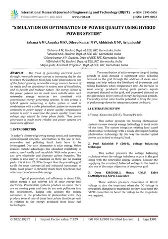
2.1 BLOCK DIAGRAM
Fig 1: BlockdiagramofPowerqualityretentionand outputpoweroptimizationinhybridhydro/PV system.
3. HYBRID ENERGY SYSTEM
Hybrid power is combinations between different technologies to produce power. Power Crisis is one ofthe top most problems in recent years. Power is usually generated using non renewable energy sources such as steam, oil, petroleum gases, nuclear, etc., for producing of such power the available raw material are not more than enough and investment cost become great issues. To run over the above issues, accumulating green energy will provide a better result. Since each green energy system is eco friendly it also has its certain demerits in power generation and hence connecting more than one unique system together will facilities continuous power generation and it will not spoil the atmosphere. Specificallyinourproject,twomajorenergyresourceslike solar, wind and hydro are used for generating uninterrupted power. Each system is designed with precise criteria and connects to form a consistent energy resource. Solarandhydro energysystemsareselectedfor theimplementation.UsingMATLAB/SIMULINKsimulation hasbeendone.
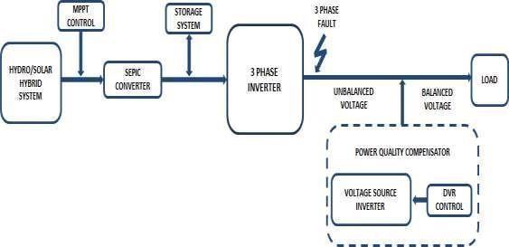
3.1 PHOTOVOLTAIC ENERGY SYSTEM
ThephotoelectricconversioninthePVjunction.PV junction (diode) is a boundary between two differently doped semiconductor layers; one is a Ptype layer (excess holes),andthesecondoneisanN type(excesselectrons). At the boundary between the P and the N area, there is a spontaneous electric field, which affects the generated electrons and holes and determines the direction of the current.
To obtain the energy by the photoelectric effect, there shall be a directed motion of photoelectrons, i.e. electricity.Allchargedparticles,photoelectronsalso,move in a directed motion under the influence of electric field. The electric field in the material itself is located in semiconductors, precisely in the impoverished area of PV junction (diode). It was pointed out for the semiconductorsthat,alongwiththefreeelectronsinthem, therearecavitiesascharge
Fig 2: FunctionofPVCell
International Research Journal of Engineering and Technology (IRJET) e ISSN: 2395 0056
Volume: 09 Issue: 07 | July 2022 www.irjet.net p ISSN: 2395 0072
Carriers, which are a sort of by product in the emergence of free electrons. Cavities occurs whenever the valence electron turns into a free electron, and this process is calledthegeneration,whilethereverseprocess,whenthe free electron fills the empty spaces a cavity, is called recombination.Iftheelectroncavitypairsoccurawayfrom the impoverished areas it is possible to recombine before theyareseparatedbytheelectric field.
Photoelectrons and cavities in semiconductors are accumulatedatoppositeends,thereby creating an electromotiveforce.Ifaconsumingdeviceisconnectedto such a system, the current will flow and we will get electricity.
Inthisway,solarcellsproduceavoltagearound0.5 0.7 V, with a current density of about several tens of mA/cm2 dependingonthesolarradiationpoweraswellas ontheradiationspectrum.
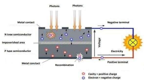
3.2 HYDROELECTRIC ENERGY SYSTEM
Inhydropowerplant potentialandkineticenergyof thewaterisusedtorotatetheturbineandhencegenerator togenerateelectricity.
4. Forebay: when there is sudden change in the turbine load, in such cases there is need of temporary storage of water. This temporary storage of water near turbineiscalledasforebay.
5. Surgetank:surgetankisbuiltinbetweendamand the valve house. It is used to take care of the system load fluctuations.
6. Penstock:itiswaterpipelinecarryingwaterfrom damtoturbine.
7. Prime mover or turbine: it is the main part of the powerstation.Itiscoupled withthegenerator. Turbineis rotated by the flow of water. As it is coupled with the generator, generator also rotates which produces electricity.
8. Powerhouse: it consists of turbine, alternator and electricalequipment.
9. Tail races: outlet water of the turbine is dischargedtotherivertroughtailraces.
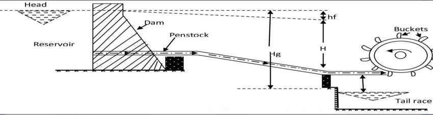
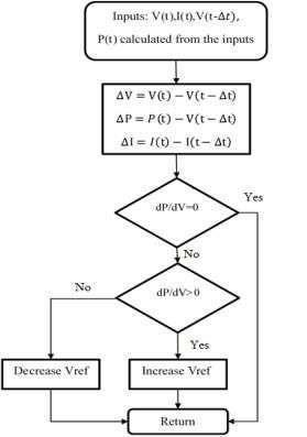
3.3 IC ALGORITHM
Algorithmsteps
Step1:Itwillcheckfortheinputs.
Step2:It will check the differencebetweeninstantaneous valueandnextintervalvalue.
Step3:Itwillverifythe/=0,ifitisyesalgorithmwillstop thisindicatessystemsioperatingatmaximumpointhence maximumpowerwillobtained.
Step4:Ifitfailsitwill checksfor/>0 thenitwill increase theVrefvalue,ifnotitwildecreasetheVrefvalue.
Fig 3: BasicLayoutDiagramoftheHydroelectricPower Plant.
CONSTRUCTION & WORKING OF HYDROELECTRIC
POWER PLANT
Following are some of the main components of the hydroelectricpowerplant.
1. Reservoir: water harvested from the catchment area is stored in the reservoir which is then used to generatetheelectricity.
2. Dam: it is made in the path of the river to make thereservoirtoholdtherainwater.
3. Pillways: Spillways are made to make the dam safe.Whenlevelofwaterisexceedssomedefinedpoint,it willdischargethroughthesespillways.
Step5:Algorithmwillstopanderrorwillberectified.
Fig 4 : FlowchartofIncrementalConductanceAlgorithm
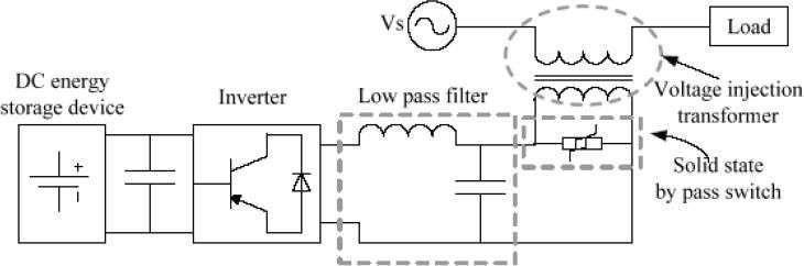
3.4 CONSTRUCTION OF DVR
Power circuitandthecontrol circuitarethe 2main parts of the DVR. There are various critical parameters of control signals such as magnitude, phase shift, frequency etc. which are injected by DVR. These parameters are derived by the control circuit. This injected voltage is generated by the switches in the power circuit based on the control signals. Furthermore the basic structure of DVR is described by the power circuit and is discussed in this section. The 5 main important parts of power circuit, theirfunctionandrequirementsarediscussedahead.
compensation ability of DVR. Among all others, lead batteries are popular because of their high response during charging and discharging But the discharge rate is dependent on the chemical reaction rate of the battery so that the available energy inside the battery is determined byitsdischargerate.
3.6 DVR OPERATING MODES
During a voltage sag/swell on the line
The difference between the pre sag voltage and thesagvoltageisinjectedbytheDVRbysupplyingthereal power from the energy storage element and the reactive power.TheDVRinjectsthedifferencebetweenthepre sag and the sag voltage, by supplying the real power requirementfromtheenergystoragedevicetogetherwith thereactivepower.DuetotheratingsofDCenergystorage and the voltage injection transformer ratio the maximum capabilityofDVRislimited.Themagnitudeoftheinjected voltage can be controlled individually in the case of three single phaseDVRs.Withthenetworkvoltagestheinjected voltages are made synchronized (i.e. same frequency and thephaseangle)
During the normal operation
During the normal operation as there is no sag, DVR will not supplyanyvoltageto the load.It will be in a standby mode or it operates in the self charging mode if the energy storage device is fully charged. The energy storage device can be charged either from the power supplyitselforfromadifferentsource.
During a short circuit or fault in the downstream of the distribution line
In this case we have seen before that a bypass switch (crossbar switch) will be activated and it will bypass the inverter circuit in order to protect the electroniccomponentsoftheinverter.
Fig 5: DVRPowerCircuit
3.5 ENERGY STORAGE UNIT
Various devices such as Flywheels, Lead acid batteries, Superconducting Magnetic energy storage (SMES) and Super Capacitors can be used as energy storagedevices.Themainfunctionoftheseenergystorage units is to provide the desired real power during voltage sag. The amount of active power generated by the energy storage device is a key factor, as it decides the
International Research Journal of Engineering and Technology (IRJET) e ISSN: 2395 0056
Volume: 09 Issue: 07 | July 2022 www.irjet.net p ISSN: 2395 0072
SIMULATION MODEL
Fig 5: SimulinkModelofHybridHydro/PVSystem
Connectedtoa3 phaseload.


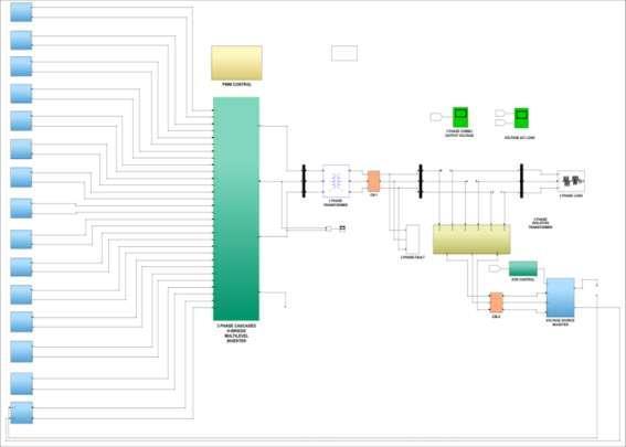
1. Run this simulation model for 1 second and observethefollowingsequenceofeventsonscope.
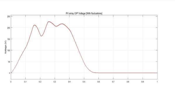
2. At t=0 sec MPPT is enabled. The MPPT regulator startsregulatingPVvoltagebyvaryingdutycycleinorder toextractmaximumpoweruptot=0.5sec.
3. From t=0 sec to t=0.5 sec, PV array starts generating voltage and this voltage will supplied to load through a SEPIC converter and Cascaded H bridge inverter.
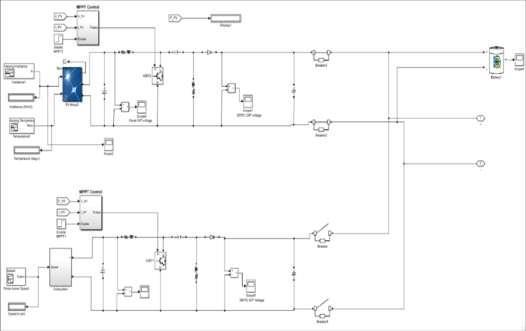
4. Fromt=0.5sechydrosystemMPPTisenabledand itsstartsregulatingahydroturbinespeedbyvaryingduty cycleusingIncrementalconductancealgorithminorderto extractmaximumpoweruptot=1sec.
5. From t=0.5 sec to t=1 sec, hydro system starts generating voltage same will be given to SEPIC converter thensuppliedtoloadthroughainverter.
Fig 6: InterconnectionofHydro/PVHybridsystem Demonstration
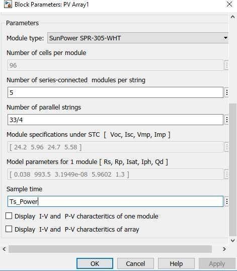
Fig 7: FunctionalBlockofPVArray
International Research Journal of Engineering and Technology (IRJET) e ISSN: 2395 0056
Volume: 09 Issue: 07 | July 2022 www.irjet.net p ISSN: 2395 0072
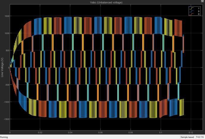
THREE PHASE, 11 LEVEL, CASCADED H BRIDG MULTI LEVELINVERTER
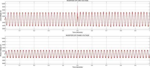
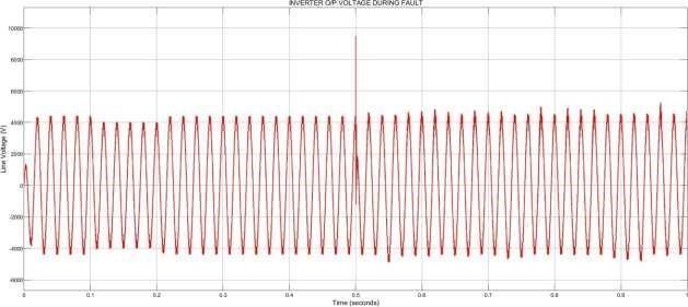
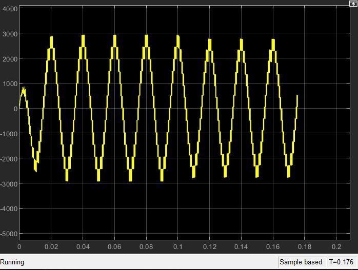
Fig 9: InverterOutputVoltageduringFault
Fig 8: InverterOutputVoltagebothLineandPhase
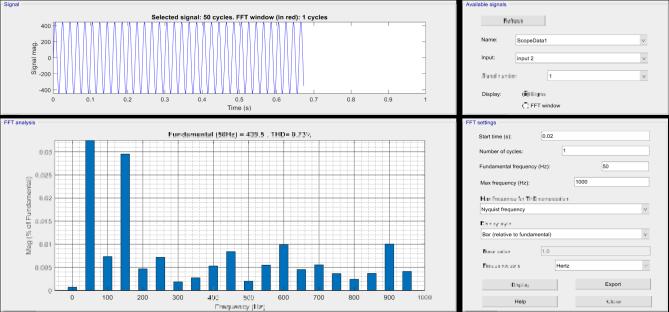
Fig-10: FFTAnalysisofOutputVoltagewithoutDVR
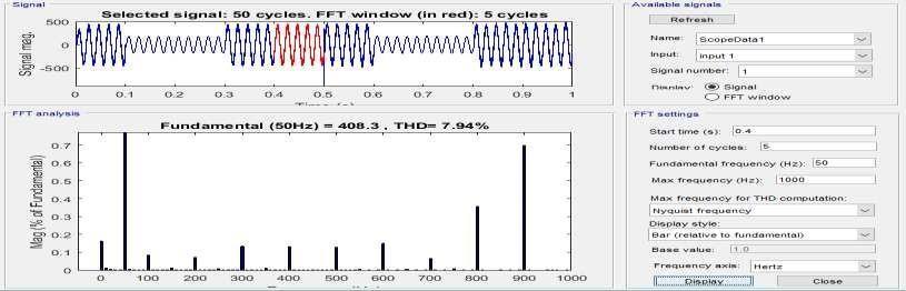
The FFT analysis carried on the output voltage showsthe THD is7.94%. Theharmonicsdistortion has to bereducedbelow5%aspertheIEEEstandards.
3.8 DYNAMIC VOLTAGE RESTORER
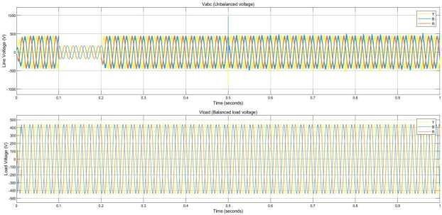
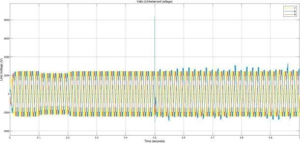
Fig 11: Unbalanced(Fault)LineVoltagewithoutDVR
Fig-12: BalancedLoadVoltagewithDVR
The Figure 8.6.2 shows the voltages during fault and the
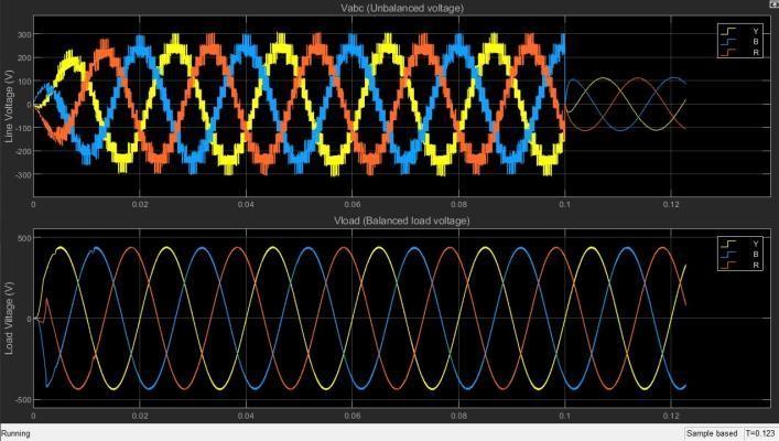
balance in voltage obtained with the employment of DVR in the system. An artificial three phase fault is created in thesystemfrom0.1 0.2seconds.Thesagintheintheload voltagethatleadstopowerqualityissuescanbeseen.The balance obtained in the load voltage is also shown the aboveFigure7.6.2.TheDVR improves boththewaveform and magnitude of the unbalanced voltage waveform, thereby improving the power quality. Also, we can see in theFigure8.6.3theincorporationofDVRhasreducedthe THDto1.06%whichisbelow5%.
4. OUTPUT
5. CONCLUSIONS
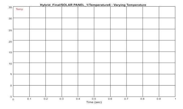
The hybrid model designed mainly focuses on the output optimization and power quality retention. The system designed is capable of maintaining its power at maximumlevelirrespectiveoftheenvironmentalchanges. The PV system operates at maximum power point even though there are fluctuations in temperature and irradiation levels also; the hydro system produces
maximum power despite the varying prime speed. Incorporationoftheincrementalconductancealgorithmof maximum power point tracking is used. The output characteristics of the Hybrid hydro/PV system are simulated considering the shading effect, varying temperature and speed. SEPIC converter is used to boost the tracked voltage and thus along with MPPT control its helps in maintaining a constant voltage. The output of CHB inverter is stepped down to 440V AC. The disturbances to the power quality caused by the faults leading to voltage sags are addressed by a power quality compensationscheme.TheDVRcontrolusedinthemodel iscapableofmaintainingthedesiredvoltageprofileofthe system thus helps in controlling the power quality of the system. The harmonics distortions present in the load voltage waveforms were observed using FFT analysis tool in MATLAB/Simulink. The total harmonic distortion is reduced to 1.06% from 7.94% with the incorporation of DVR. The functionality of the entire proposed model has been demonstrated by simulation, and the results obt IRJET sample template format ,Conclusion content comes here. Conclusion content comes here Conclusion content comes here Conclusion content comes here Conclusion content comes here Conclusion content comes here Conclusioncontentcomes hereConclusioncontentcomes here Conclusion content comes here Conclusion content comes here Conclusion content comes here Conclusion contentcomes hereConclusioncontentcomes here.
International Research Journal of Engineering and Technology (IRJET) e ISSN: 2395 0056
Volume: 09 Issue: 07 | July 2022 www.irjet.net p ISSN: 2395 0072
REFERENCES
1. Sweeka Meshram, Ganga Agnihotri and Sushma Gupta, “Modelling Of Grid Connected DC Linked PV/Hydro Hybrid System”, Electrical and Electronics Engineering: An International Journal (ELELIJ)Vol2,No3,August2013
2. M.G. Villalva, J.R.Gazoli, and E.R.Filho, “Comprehensive Approach To Modeling And SimulationOfPhotovoltaicArrays”, IEEE Trans. On powerElectron.Vol.24,no.5,May2009.
3. Approach To Modeling And Simulation Of Photovoltaic Arrays”, IEEE Trans. On power Electron.Vol.24,no.5,May2009.
4. Auwal Abubakar Usman, Rabiu Aliyu Abdulkadir, “Modelling And Simulation Of Micro Hybrid Plant Using MATLAB Simulink”, 2ND international conference on science, technology andmanagement27September2015.
5. Nicola Femia, Giovanni Petrone, Giovanni Spagnuolo and Massimo Vitelli(2005) “Optimization Of Perturb And Observe Maximum Power Point Tracking Method,” IEEE transaction onpowerelectronics,vol.20,no.4.
6. Rakshith P, Jahnavi R Bhat, Ashwini M, Rakshitha C R, Vinay kumar Sharma, “Photovoltaic Power Control Using MPPT And SEPIC Converter”, PionEEEr 2017.
7. Faete Filho, Yue cao, Leon M. Tolbert. “11 Level Cascaded H Bridge Grid Tied Inverter Interface WithSolarPanels”, 201025th IEEEAPEC.

8. Sanjay A Deokar, Laxman M Waghmare, “DVR Control Strategy For Dynamic Power Quality Disturbance Mitigation”, international journal of science and research publications, vol 2, issue 11, November2012.
BIOGRAPHIES
Author 1:
Sahana A M, Iamcurrentlypursuing B.E Degree in Electrical and Electronics Engineering in the year 2022 from Rajeev Institute of Technology, Hassan 573201,Karnataka

Email: sahanagowdaam@gmail.com
Author 2:

Anusha M K, Iamcurrentlypursuing B.EDegreein Electrical and Electronics Engineering in the year 2022 from Rajeev Institute of Technology, Hassan 573201,Karnataka
Email: mkanusha103@gmail.com
Author 3:
Dileep Kumar N V, I am currently pursuingB.EDegreein Electrical and Electronics Engineering in the year 2022 from Rajeev Institute of Technology, Hassan 573201,Karnataka
Email: dileepnayak23@gmail.com
Author 4:
Abhishek U M, Iamcurrentlypursuing B.EDegreein ElectricalandElectronics Engineeringintheyear2022from RajeevInstituteofTechnology,Hassan 573201,Karnataka
Email: aabhi8933@gmail.com

Author 5:
Mr.Arjun joshi received the B.E. degree in Electrical and Electronics Engineeringintheyear2019fromSDM institute of technology ujire and Postgraduation degree in Power System EngineeringfromTheNationalInstitute of Engineering (NIE), Mysore in the year 2021.he is working as Assistant professor in department of Electrical and Electronics Engineering at Rajeev institute of technology Hassan Karnataka. He has 01 years of teaching experience. He published one InternationalJournals. His research interest includes Power System Operational Planning and Control, Distribution System Network Reconfiguration, Service Restoration, Distribution System Automation and Distribution Generation, electric vehicle technologies,powerquality.