International Research Journal of Engineering and Technology (IRJET) e ISSN: 2395 0056
Volume: 09 Issue: 07 | July 2022 www.irjet.net p ISSN: 2395 0072
International Research Journal of Engineering and Technology (IRJET) e ISSN: 2395 0056
Volume: 09 Issue: 07 | July 2022 www.irjet.net p ISSN: 2395 0072
B.E. Student1,2,3,4, Assistant Professor5 Department of Mechanical Engineering Nutan Maharashtra Institute of Engineering and Technology, Talegaon Dabhade, Maharashtra, India ***
Abstract: This paper is an over view of the commonly used welding joint’s while welding any workpiece. Also, the fixture used, to position the workpiece while welding is discussed While welding while welding many irregularities, poor weld, imperfections are formedand are classifiedinmanytypes.The types of welding defects are also part of this paper along with their detection process. And one of the important welding processes i.e. CO2 arc welding process, the welding in which a consumable filler material used and is used to get deep penetrations while welding, is discussed. Now, different welding conditions have different effects on the weld, this welding conditions can be the metal being welded, forehand/backhand welding, welding velocity, etc.
Keywords: arc welding, defects, fixtures, joints, welding, CO2 arc Welding, conditions
Weldingisa fabricationprocesswheretwoormoreparts arefusedtogetherbyapplyingveryhighheatandsometimes pressure.
Weldingismostimportantandessentialprocessin industrial world. CO2 Welding is commonly used in automobile industry, construction industry, fabrication industry,aviationindustry,etc.
In Gas Welding process is done by using the heat flame caused by a reaction of oxygen and fuel gas, metals are melted and joined together. For gas welding if the loss of heat is too rapid the weld will develop many cracks. To provide enough support to weldment, large masses of the fixturearekeptawayfromtheweldingpoint.
Inarc weldinginwhichelectricityisusedtocreatea high temperatureforwelding,Temperatureishigherthanthegas welding. The fixture used in arc welding should apply enough force to firmly hold the workpiece, also it should
easily dissipate heat. And this fixture should also provide properalignmentaswellassupporttotheworkpiece.
ForResistanceweldingmainlytwotypesoffixtureareused firstisthecombinedunitofbothmachineand thefixture. Andsecondisthefixturetospecificweldingmachineswitha single electrode. Insulation plays an important role for fixtureshere,allthemagnetics,especiallyferrousmaterials should be kept away from the welding machine, and the fixtureshouldbemadeofnon magneticmaterials.
In laser welding a high intensity laser beam is incident, where the welding is needed, this melts the material and thusjoinstheelements.Itismostpopularlyusedwherehigh precisionisneeded.Thefixtureshouldbemadesuchthatit prevents the vibration, also height should be maintained properly.Andalso,thereshouldbesufficientspacebetween theworkpieceandotherpartstobewelded.
AirFiltersusedinautomobileshavetwofanswhichneedto beweldedontotheshellofthefilter.Thefixtureusedhelpsto maintain the eccentricity, height and angle. It has a lower base,supportedwithfourrodthistablehasacentralrodto hold the fan in proper position and also an arrangement made to hold the shell in proper position to maintain the eccentricity.ModelingoffixturesisdoneusingCreosoftware. Thisfixtureiseconomical,easytouse,work,hashighdegree ofaccuracy,timeofoperationisreduced.
Intoday’sfast movingworldroboticweldingiscommonly used. The fixture used for robotic welding needs to be accurate, this will increase the efficiency and quality. This
2022, IRJET | Impact Factor value: 7.529 | ISO 9001:2008 Certified Journal

International Research Journal of Engineering and Technology (IRJET) e ISSN: 2395 0056
Volume: 09 Issue: 07 | July 2022 www.irjet.net p ISSN: 2395 0072
fixture base can tilt rotate along x axis, can do translation movement and allow rotate along z axis in relation with slider. The worktableisofhexagonal shape.Alsohasrack andpinionarrangementalongwithadjustableclampingto hold the work piece. This fixture helps in clamping workpiecesofvarioussizesandgeometries.
The fixture is used for the footrest stand, where the componentistobelocatedwithhighaccuracy.Thisfixture has a rest plate, which has three pins to restrict the movement of the workpiece. There are few locating pads whichareusedtoalignandlocatethecomponentandfixthe bushes accurately. First the bushes are placed accurately using clamps and then are welded round and welded accordingly.Oncetheweldingoperationisdone,theclamps of the fixture will get detached. Solid works modeling softwareisusedformodeling.
The motor case is approximately 4m long, it comprises 4 mainpartsi.e.2tubes,rearendandhead.Also,someother partslikebrackets,clampsneedtobemounted.So,fixture design has high accuracy satisfying the above needs. The fixture has a collapsible assembly and roller support assemblytoavoidthedeflectionofthetubes.Thefixturehas asequentialsetuptoimprovethequality.Also,clampsare provided to achieve appropriate tolerance. The modeling softwareusedfordesigningelementsisUNIGRAPHICSNX 8.0.
The fixture used for the door frame should possess more clinching power, and should hold the door frame rigidly. Also, the clamping used for properpositioningshould not restrict the welding and should be easily removable once weldingis done. The fixture ismade ofa base plateand 2 rectangular blocks are mounted to hold each strip of the door frame in rectangular positions. The strips are held together(tightened)usingcotters.Thefixtureisinaslanting positionwithrespecttothesurfacetogetproperwelding done. The fixture is portable and has many industrial applications.
Themountingofthefueltankconsistsof6partswhichare neededtoweld.Thefixtureusedforthefueltankmounting brackethasarotatingplatemountedonaplumbingblock whichhelpstotiltthefixtureby45o,whichismountedona bearinghousingwhichcanrotateupto180o inhorizontal direction.Inthismountingthedistanceplaysanimportant role,sothefixturehaslocatorpinstolocatethedistance,if duetosometechnicalissuethedistanceisnotmaintainedan alarmgivesthesignalforthemisalignment.Also,ifthereis
anymisalignmentinthebrackettheweldingtorchdoesnot work. Thus, this fixture helps to maintain the quality and accuracyofthemountingbracket.
Welding Joint is referred to as joining or fitting of metal surfacesinpriorarrangementorconfigurationaccordingto requirement. Application of welding joints can be endless becauseofitsmonopolyofuseintheindustryintoday’sera.
According to AWS (American Welding Society) types of weldsareclassifiedinto5types:
1.Buttjointwelding 2.Lapjointwelding 3.Edgejointwelding 4.Teejointwelding 5.Cornerjointwelding
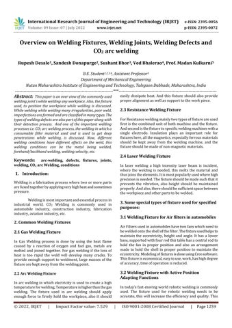
ButtJointWeldingisatypeofweldingwheretwoadjacent surfacesarejoinedtogether.ApplicationofButtweldingisit is used in pipes, fabrication of structures, valve fittings, automotivepartsetc.
TypesofButtWelding: 1.Squarewelding
Singlebevelwelding
Doublebevelwelding
V groovewelding
DoubleV groovewelding
U groovewelding
DoubleU groovewelding
J weldingwelding
DoubleJ groovewelding
Fig. 1: ButtJointWelding
International Research Journal of Engineering and Technology (IRJET) e ISSN: 2395 0056
Volume: 09 Issue: 07 | July 2022 www.irjet.net p ISSN: 2395 0072
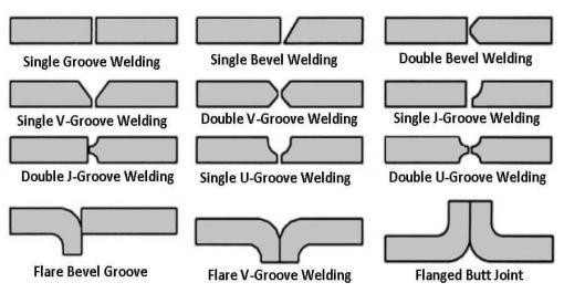
Lap Joint Welding is a type of welding where the overlappedmetalsurfacesarejoinedorfittedtogether.It iswidelyusedincombinedelectronbeam,laserbeam,and resistancespotwelding.Lapjointsareoftenusedonthick materials,andareusedforsheetmetal.
Somedrawbacksoflapjointweldingarelamellartearing and corrosion due to the overlapping of fall metals. But you can easily handle them by applying the correct techniqueofmodifyingthevariables
Followingarethetypicalexamplesoflapjoints.
1.Filetwelding 2.Spotwelding 3.Plugwelding 4.Slotwelding 5.Bevelgroovewelding 6.Flarebevelgroovewelding 7.J groovewelding
Fig. 2: LapJointWeldingTypes
defectsinedgetypeweldingareporosity,lackoffusion,lava inclusion,etc.
TypesofEdgeJointWelding:
1.V groovewelding 2.U groovewelding 3.J groovewelding 4.Bevelgroovewelding 5.Squaregroovewelding 6.Cornerflangewelding 7.Edgeflangewelding
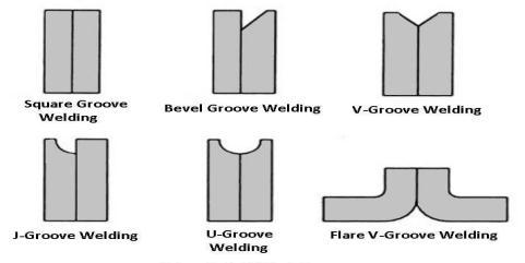
Fig. 4: EdgeJointWelding
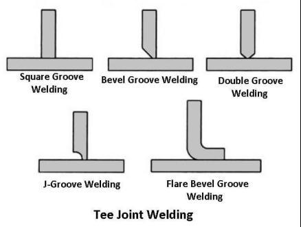
In Tee Joint Welding, when the two metal plates are at angleof90°withoneplateislieonthecenteroftheother platelikea"T"shape.Itisknownasteejointwelding.But, again wewill have a drawback in the tee joint, which is lamellartearing..
Followingareexamplesofteejointwelding.
1.Plugwelding
2.Slotwelding 3.Bevelgroovewelding 4.Flarebevelgroovewelding 5.Filletwelding 6.J groovewelding 7.Meltthroughwelding
Similartolapjointwheretheparallelsurfacesarejoinedor fixed together at the point of welding. It is often used for joiningtheedgesofsheetmetalormufflers.Usedinareas likelowpressureandstress.Itisnotaverystrongjoint.The
2022, IRJET | Impact Factor value: 7.529 | ISO 9001:2008 Certified
International Research Journal of Engineering and Technology (IRJET) e ISSN: 2395 0056
Volume: 09 Issue: 07 | July 2022 www.irjet.net p ISSN: 2395 0072
Weldingdefects(flaw)aretheunwantedirregularities or discontinuities that are present in the welding product,whichisnotacceptableunderthestandardized rules and regulations. Which later lead to wear and failure of the weld and cause damage and loss to the entireproductorenvironmentinwhichit’sbeenused.
AccordingtoAmericanSocietyofMechanical Engineers(ASME)welddefectorflawarecauseddue tofactors
1. 45%poorprocessconditions.
2. 23%operatorerror. 3. 12%wrongtechnique.
Similar to tee type welding joint, the difference is the positing of the metal surfaces in tee type the metals are placedinthemiddlewhileincornerjointweldingthemetal surfaceisplacedatthecornerend.Applications,ofcorner joint welding are there are used in joining sheet metal surfacesalsousedinmanufacturingofboxes,frames,bars etc.
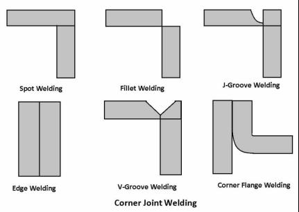
TypesofCornerJointWelding: 1.Filletwelding 2.Spotwelding
Edgewelding 4.J groovewelding
U groovewelding
V groovewelding
FlareV groovewelding
Squareorbuttgroovewelding
Cornerflangewelding 10.Bevelgroovewelding
Fig. 6: CornerJointWelding
4. 10%incorrectconsumable(fillermaterial/rod). 5. 5%Badweldchannel.
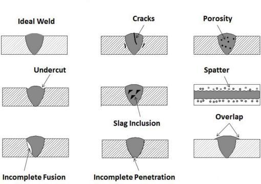
A.ExternalWeldingDefects. a.Cracking b.Porosity c.Undercut d.Overlap e.Spatter B.InternalWeldingDefects. a.Slaginclusion b.Lackoffusion c.Incompletepenetration d.Shrinkagecavities
as
Shieldinggasalsoaffectsthequalityandstrength oftheweld,wemostlyuseCarbondioxide.
As it is 1.5 times heavier than air and has a high oxidizingpotential.Anditgivesfewdefects.
International Research Journal of Engineering and Technology (IRJET) e ISSN: 2395 0056
Volume: 09 Issue: 07 | July 2022 www.irjet.net p ISSN: 2395 0072
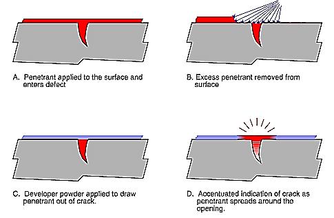
Dyepenetrationtestisusedtoidentifyandlocatethesurface inallnon porousandnon magneticmaterials.
Inthismethodfirstweneedmakethesurfacecleanandthen applycolordyeontheweldsurfacewiththehelpofspraying or brushing, then the extra dye is removed and then we apply the developer which helps us to clearly notice the defectsthatarepresentontheweld.
RadiographictestingmethodisNon destructivetestingused for the identification of internal defects or internal discontinuitiesintheweld.
This method is based on short wavelength electromagneticradiation.Whichispassedthroughmaterial andwegetaradiographicfilmonthescreen.
Fig. 8: Dyepenetrationtest
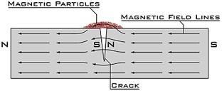
Magnetic particle inspection is a simple Non destructive testing to find irregularities and weld flaws in magnetic materials.
Inthismethodfirst,thespecimenispassedthrough anelectriccurrenttogetamagneticfieldorwecreateitwith thehelpofanexternalmagneticfield.Andtheedgeofthe crackwillbenorthandsouthpolesnowifpresentandwe sprinkleironparticlesthatareattractedtothecrackedges andwegettoknowthedefects/flaws.
Fig. 10: Dyepenetrationtest
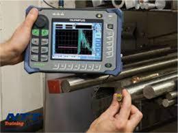
UltrasonicTestingmethodisNon destructivetestingused forthethicknessofthematerialandflawdetection.
In this method first we pass the high frequency (0.5MHz to 20MHz) sound waves which travel through in different speeds in different materials. The sound wave signalsarereflectedbackandthenwegettheresultsonthe screenandcanknowabouttheflaws.
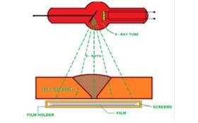
Fig. 9: Magneticparticleinspection
Fig. 11: UltrasonicTesting
International Research Journal of Engineering and Technology (IRJET) e ISSN: 2395 0056
Volume: 09 Issue: 07 | July 2022 www.irjet.net p ISSN: 2395 0072
VisualInspectionisaNon destructiveexaminationmethod mostlyusedforqualitycontrol,dataanalysisandchecking thecorrectnessvisually.InthismethodtheInspectorwhois anexperiencedpersonofthefieldistheretotakeacloser lookandfindouttheflawsanddefectsoftheweld.
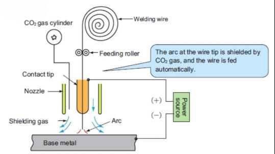
In CO2 arc welding, the filler welding wire is fed into the welding torch with the help of a motor. To protect the welding material from reacting with atmospheric oxygen andnitrogen,CO2gasissuppliedfromthenozzletoshield theweldingpoolarea.
short circuiting with it. It is suited for welding thin plates and in all position welding such as vertical or overhead welding.
In high current CO2 arc welding, the mode of droplet transfer becomes globule transfer mode. In this, a slightly higheramountofspatterisemittedthaninothermodes.But itisusedasitishighlyefficient.
MIGweldingusesDCelectrodewithinertgasshieldingand positivepolarity,whichleadstoformationofsmalldroplets thanthewirediameterduetotheeffectofplasmaflow.This means the emission of spatter is little and the weld bead withagoodappearancecanbeobtained.
8.1
Fig. 12: CO2ArcWelding
Theweldedmaterialhavingblowholesisnotagoodthingor considered good. CO2 gas is decomposed by the high temperaturearcheatintoCOandOnearthearc.NowOin FeOcombineswithSiandMnandfloatsuponthesurfaceof theweldpool. CO2 ⇆CO+O FeO+O⇆FeO FeO+C⇆Fe+CO FeO+Mn⇄Fe+MnO 2FeO+Si⇆2Fe+SiO2
Theprocessofmeltingafeedingwireandpassingittothe base metal can be done in three different ways i.e. short circuitingtransfer,globuletransferandspraytransfer.
IfalowweldingcurrentisusedinCO2arcweldingorMIG welding,thedropletsaretransferredtothebasemetalafter
8.2
welding speed is increased 1. Penetrationbecomeslessdip 2. Spatterincreases 3. Undercuthappensifspeedisexcessive 4. Highweldingreinforcementisrequired 5. Beadbecomeslesswideandnarrower
Base Contact
1. Staggeredbeadappearance 2. When feed rate is constant welding current decreasesandthepenetrationdecreases
1. As the gas shielding effect reduces the porosity increases
8.4
2. Thesplattertendstoblockthenozzleandwelding qualitydecreases 3. Wecan’tseethelineofweldingasthenozzleistoo closetotheline
1. Moredeeppenetrationthannormal 2. Higherweldreinforcement 3. Widerbeadwidth
8.6 Welding torch
for forward welding 1. Beadwidthincreases 2. Lesspenetration
International Research Journal of Engineering and Technology (IRJET) e ISSN: 2395 0056
Volume: 09 Issue: 07 | July 2022 www.irjet.net p ISSN: 2395 0072
3. Higherreinforcementisrequired
1. Whentheflowrateisloworhighwindsareflowing porosityoccurs
2. Itscompositionaffectsthepropertiesoftheweld
1. Contaminantswilldamagethequalityoftheweld andcauseporosity
1. Wecaneasilytargetthefeedingwireonthewelding line
2. Lessreinforcementandflatbeadshapeisachieved 3. Consistent melting is achieved through the root passbead
4. Asmoltenmetalflowsaheadshallowpenetrationis achieved
1. As welding nozzle hides the line to be welded, weldingisalittledifficult
2. High reinforcement and narrow bead shape is achieved
3. Itishardtoobtainconsistentmeltingthroughthe rootpass
4. As the molten pool is formed backwards deep penetrationisachieved
X raytestshaveshownthatthereisasharpincrease ofblowholeswhenthewindisover2m/sec.invelocityand theweldbeadisdepositedona9mmthickplate.
1. CO2gasflowshortage 2. Thegasheaterisnotworkingproperly 3. CO2gasisnotpureenough
4. Gasshieldingisnotproper
1. Weldingcurrentistoolow
2. Weldingcurrentistoohigh 3. Toolowarcvoltageorweldingspeed 4. Weldingwireistargetingthewrongposition
1.Weldingcurrentistoohigh
1. Voltageistoohigh 2. Weldingspeedistoohigh 3. Thereisroughmanipulationoftheweldingtorch
1. There isa deviationinthecenter of thewirefees roller
2. Thecontacttipisloosened 3. Wirestraightenerisnotadjustedproperly
1. Weldingcurrentistoolow 2. Arcvoltageistoolowortoohigh 3. Weldingspeedistoohigh 4. Weldingwireistargetedinawrongposition
Thus, we have overviewed Welding Fixtures, Welding Joints,WeldingDefectsandCO2 arc welding.also analyzed about the parameters and properties affect weldingofjointsandweldingdefects.
[1] Prashant Songire, 2 Jayesh Patil, 3 Pankaj Patil, 4 ShubhamGhodake,‘DesignandManufacturingofWelding Fixture’, International Journal of General Science and EngineeringResearch(IJGSER),ISSN2455 510X,Vol3(2), 2017,87 89.
[2]JeffreyJ.Madden,‘WeldingFixturewithActivePosition Adapting Functions’, A Major Qualifying Project Report, WORCESTERPOLYTECHNICINSTITUTE,Date:7/31/2007
[3] Siddesha K, Dr. D. Ramegowda, ‘Design of a Welding Fixture and Analysis for the Footrest Stand Component’, InternationalJournalofEngineeringResearch&Technology (IJERT)ISSN:2278 0181IJERTV4IS041164,Vol.4Issue04, April 2015.
[4] Naveen A M, V A Girisha, Pruthvi H M, ‘Design and Analysis Of Welding Fixture For Motor Case Assembly’, International Journal Of Mechanical And Production Engineering,Issn:2320 2092,Volume 2,Issue 8,Aug. 2014.
[5] Dr.G.Arunkumar, C.A.Arjun,Wahid Hussain, S.K Vishal, PrabhuBalaGanapathi,ShahulHameed,A.Sivasubramanian , ‘Design and Fabrication of Welding Fixture for a Single Doorframe’, International Journal of Scientific Research Volume : 3, Issue : 11, November 2014, ISSN No 2277 8179.
2022, IRJET | Impact Factor value: 7.529 | ISO 9001:2008 Certified Journal
International Research Journal of Engineering and Technology (IRJET) e ISSN: 2395 0056
Volume: 09 Issue: 07 | July 2022 www.irjet.net p ISSN: 2395 0072
[6]Prof.A.A.Karad,BrijeshwarWagh,AjayShukla,Niladhari Pyata,ChetanGujar,‘DesignandManufacturingofWelding Fixture for Fuel Tank Mounting Bracket’, International JournalofEngineeringResearchandGeneralScienceVolume 4,Issue2,March April,2016ISSN2091 2730.
[7]N.B.Pawar.,Prof.P.P.Patil,Prof.R.Y.Patil,‘AReview: Design and Analysis of Welding Fixture for the Rack and Pinion Assembly’, 2017 IJSRSET, Volume 3, Issue 1, Print ISSN:2395 1990,OnlineISSN:2394 4099ThemedSection: EngineeringandTechnology.
[8] Rimantas Didžiokas, Jolanta Janutėnienė, Jurgita Jonaitytė,‘Theimpactofinternalweldingdefectsonthejoin strengths.Received14January2008;accepted12June2008.
[9] Barkhatov, V. A. 2003. Development of methods of ultrasonicnondestructivetestingofweldedjoints,Russian JournalofNondestructiveTesting39(1):23 47
[10]C.H.Kim,Y.N.Ahn,J.H.Kim.“CO2laser microplasma arc hybrid welding for galvanized steel sheets”. Trans. NonferrousMet.Soc.China21(2011)s47 s53.
[11] Lu Dengping, Zhang Shaobin. Study on Mechanism of Mutual EffectBetweenLaserandArc &ItsEffecton Weld Penetration.ChinaWelding.Vol.2:February,1993;pp.104 108
[12]Bayock,F.N.;Kah,P.;Layus,P.;Karhin,V.Numericaland experimental investigation of the heat input effect on the mechanicalpropertiesandmicrostructureofdissimilarweld jointsof690 MPaQTandTMCPsteel.Metals2019,9,355
[13] N. Nacereddine, M. Zelmat, S. S. Belaïfa and M. Tridi, “Weld defect detection in industrial radiography based digitalimageprocessing”InternationalConference:Sciences of Electronic, Technologies of Information And TelecommunicationsMarch27 31,2005 Tunisia
[14] Yan Hanbing, Zhao Lina, Ju Hui, “Research on SVM Based Classification for Welding Defects in Radiographic Testing”978 1 4244 4131 0/09/2009IEEE
[15] Alireza Azari Moghaddam, Lalitha Rangarajan, “A method for detection welding defects in radiographic images”InternationalJournalofMachineIntelligenceISSN: 0975 2927&E ISSN:0975 9166,Volume3,Issue4,2011
[16] Sonit Singh ‘Analysis of various defects involved in welding metallurgy’ International Journal of Pure and AppliedMathematicsVolume120No.62018,6267 6280
[17]HamidRezaGhazvinloo,AbbasHonarbakhsh Raoufand NasimShadfar,‘EffectsofRoboticCO2ArcWeldingVariables on Penetration and Microstructure of Weld in C 80 Grade Steel’,10Mar2010
2022, IRJET | Impact Factor value: 7.529 | ISO 9001:2008 Certified Journal