International Research Journal of Engineering and Technology (IRJET) e ISSN: 2395 0056

Volume: 09 Issue: 07 | July 2022 www.irjet.net p ISSN: 2395 0072
International Research Journal of Engineering and Technology (IRJET) e ISSN: 2395 0056
Volume: 09 Issue: 07 | July 2022 www.irjet.net p ISSN: 2395 0072
1 ,
Prof. Ashish Duvey2
1 Research Scholar,Dept of Digital Communication Shri Ram College of Management and Technology Digital communication
2 Assistant professor,Dept of Digital Communication Shri Ram College of Management and Technology Digital communication ***
Abstract Despite the rapid growth of the photovoltaic (PV) industry, most of the energy demand in the India is supplied by fossil fuel power plants. One of the main reasons for this is that PV is non dispatchable, meaning it is limited to times when the sun is shining. Because of this, utilities must maintain reliable grid infrastructure for times when PV is not available but there is still demand, such as in the evening when the sun has gone down but the electricity demand is greatest. This leads to electricity infrastructure going unutilized much of the time, wasting valuable resources while fossil fuel power plants are still harming the environment. The non dispatchable nature of PV limits the amount of PV that can be connected to the grid. One remedy for this limit is to add energy storage to PV systems, or to shift deferrable loads from times of peak electricity demand to times when the sun is shining. With storage, batteries can be charged when the sun is shining, and discharged when the electricity demand is highest. Energy storage and load shifting allow more loads to be met locally rather than importing energy from the grid, or exporting excess PV production to the grid. This process is known as self consumption. 1246 v This study compares the levels of self consumption in a PV self consumption system with and without the use of battery based energy storage. It also compares four different load shifting load profiles against a baseline load profile without load shifting.
KeyWords: Solar, Pv, Grid, Autoselection.
Asenergygenerationanddistributioncompaniescompete inthemarketplace,wehaveseenanincreasinginterestin renewable and alternative energy sources. In addition to this competition, companies are seeking demands from customers for higher quality and cleaner electricity. Also, considering the worlds coal stocks are reducing and the creationoflegislationwhichispushingforgreenerenergy solutions, we are led to seek new energy generation methods. One solution which is currently attracting attention is Micro Grid systems [1] [2]. A Micro Grid is a low voltage or medium voltage distribution network which consists of a cluster of micro sources/distributed
generators, energy storage systems and loads, operating as a single controllable system. In a MG, the distributed generators should have sufficient capacity to carry all, or most, of the load connected to the MG. Distributed generators are located at strategic points, normally at the distributionlevel,nearloadcentres,andusedforcapacity support, voltage support and regulation, and line loss reduction[2].Themicro sourcesordistributedgenerators are usually made of many new technologies, e.g. fuel cell, photo voltaic system and several kinds of wind turbines. These units having small capacities are interfaced with power electronics and are placed at the consumer sites. Power electronics provides the control and flexibility requiredbythemicrogridsystem.Theinclusionofenergy storagesystems(batteries/flywheels/supercapacitors)in aMicrogridsystemallowstheexcesspowerproduced,to be stored or alternatively the excess power could be put intothemaingrid[3] [4].Micro gridisinevitableinfuture due to its obvious advantages in reduced central generation capacity, increased utilization of transmission & distribution capacity ,enhanced system security and reduced CO2 emission. However, micro grid adds a number of complexities in control and protection aspects inatraditionaldistributionsystem.
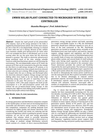
Fig. 1.1 shows that the global Solar PV installation capacity has been exponentially increasing over the past twodecades,recording237.3GWin2015.Thisrepresents more than tripling of its global capacity in 2011[2]. Utilization of Solar PV systems has gained global acceptance for several reasons, i.e., availability of solar irradianceinmanyregions,absenceofmovingpartsinthe generation system, decline of PV panel’s cost, and low operationandmaintenancecosts. However,Solar PVunits are intermittent source of power due to the unexpected solar irradiance change and temperature. Strategically, Battery Energy Storage System (BESS) can play a salient role in a microgrid by addressing any mismatch between the intermittent Solar PV generation and power demand. BESS also can provide ancillary services such as voltage and frequency regulation, reactive power support, load leveling,peakshaving,andpowerqualityimprovement[3].
International Research Journal of Engineering and Technology (IRJET) e ISSN: 2395 0056
Volume: 09 Issue: 07 | July 2022 www.irjet.net p ISSN: 2395 0072
Rohan R. Pote and Dipti D. Patil (2017) proposed the traditional method for the mixing of more than one renewable resources and power input converters for every source and calls for a greater range of converter stages main to sizeable reduction in reliability and performance of the gadget. In order to deal with this problem, a energy flow management battery primarily based grid connected unmarried section electricity generatingdcconverterisproposed.
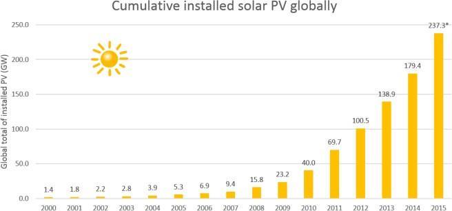
Figure1.1:TotalinstalledSolar PVaroundtheworld forthepast15years[2].
G. Suresh (2018) proposed on this paper, a manage method for energy glide management of a lattice related go breed PV battery primarily based gadget with a productive multi enter transformer coupled bidirectional dc dc converter is brought. The proposed gadget expects to fulfil the heap request, address the strength glide from numerous resources, infuse surplus strength into the lattice and rate the battery from matrix as and while required.
Ramendra Kumar et al. (2018) proposed hybrid electricity system may be utilised to decrease energy storage wishes. There's increasing hobby for using exchange or belongings strength resources to perform accurateandeasestrengthforResidential Application the PV hybrid device restores the most decreased value esteems to stay up an equal degree of DPSP once contrasted with independent sun and structures. For all heap requests the levelized strength taken a toll for PV hybrid gadget is reliably beneath that of independent sun PVor gadget.
J. Mano Priya and T. Narasimha Prasad (2018) proposed a grid related hybrid system inclusive of photovoltaic (PV) array, turbine, and battery storage are considered and a control strategy for power glide management of the considered hybrid machine with an efficient transformer coupled bidirectional dc dc converter is presented. This transformer is used to interface the non traditional electricity assets to the main dcbusofthedevice.
M. Bijomerlin et al. (2017) presented efficient use of hybrid strength for three phase domestic packages is presented on this paper. The proposed hybrid machine managestheenergywaftfromsun batteryresourcesand the battery is charged when required from the grid. The proposed converter includes a half bridge converter to harnessthepowerfromsunandbatterythrubidirectional greenback improve converter and energy from thru the dioderectifier.
Amit Kumar Gupta et al. [54], cautioned a simple SVPWMsetofrulesforamultilevelinverterforoperation withintheovermodulationvariety.Theproposedscheme easily determines the vicinity of the reference vector and calculateson instances.
In the grid connected mode of operation, the microgrid’s voltage and frequency are determined by the utility grid. The grid supplies any power deficit and absorbs any surplus power of the microgrid system. The proposed control strategy regulates the solar PV units to exchange real and reactive power with the microgrid through the current controller of their VSC systems while tracking their MPPs.Thecontrol strategyalsocontrolstheBESS to satisfy its SOC constraints while regulating the active and reactive power through the current controller of its VSC system. The control strategy in the grid connected mode hastwomainfunctions.i)extractingthemaximumoutput powerfromthethreeSolar PVunitsbasedontheirMPPT controls. ii) controlling the battery SOC at a certain level whichcansupportthemicrogridvoltageandfrequencyin the islanded mode. The proposed control strategy attempts to keep the BESS in the grid connected mode in an idle state, i.e., neither charging nor discharging, which reduces the number of charging/discharging cycles and extendsbatterylife[33].
International Research Journal of Engineering and Technology (IRJET) e ISSN: 2395 0056
Volume: 09 Issue: 07 | July 2022 www.irjet.net p ISSN: 2395 0072
Figure 4 depicts the control structure of the BESS. The LC comprises a SOC constraints logic and the VSC system control. The SOC constraints logic provides the reference real power while the SC provides the reference reactive power to the VSC system. In this thesis, it is assumed that thereisnoreactivepowersupportprovidedbytheBESSin the grid connected mode, therefore, the SC sets the referencereactivepower(Qs_ref)oftheBESStozero.
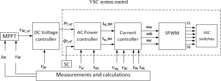
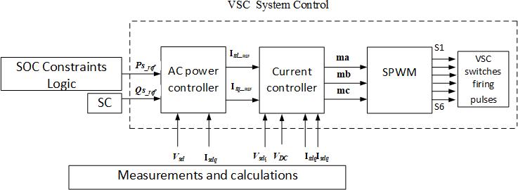
Figure2:Theproposedcontrolstrategyforthemicrogrid systeminthegrid connectedmode.
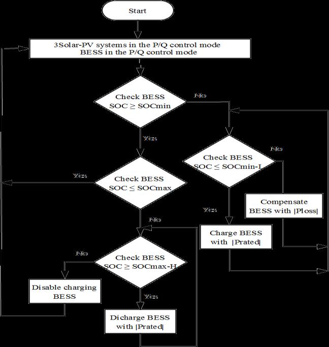
Figure 3 shows the LC of each Solar PV unit which includesaMaximumPowerPointTracking(MPPT)control, a DC Voltage controller and the VSC system control. The MPPTprovidesthe referenceDCvoltagetotheDCvoltage controller. The DC voltage controller generates the reference real power (Ps_ref) for the VSC system control. The current controller of the VSC system controls the VSC output power to track the AC power reference generated fromtheDCvoltagecontrollerbyprovidingthemodulation indexesfortheSPWMschemeoftheVSC.Inthisthesis,itis assumedthat thereisnoreactivepowersupportprovided bytheSolar PVunits,i.e.,theSCsetsthereferencereactive power(Qs_ref)oftheSolar PVunitstobezero.
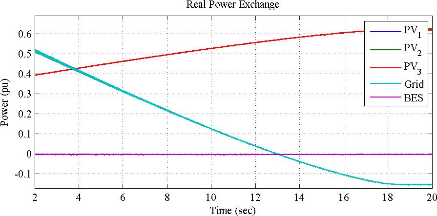
Figure4:Schematicdiagramofthecontrolsystemofthe BESS.
Figure5(a)showsrealpowerexchangeofthethreeSolar PV units and the BESS with the utility grid. The three Solar PV units operate under similar conditions and thus, theiroutputpowercurvesareoverlapped.Thesimulation starts, when each Solar PV unit supplies 0.4 pu to the microgrid, the utility grid supplies 0.51 pu to the microgrid and the battery initial SOC is 0.73, which is within the pre specified range (70% 75%). Thus, the BESS output power is zero during this case and the SOC remainsconstantasshowninFig.5(b).
(a)
Figure3:Schematicdiagramofthecontrolsystemof eachSolar PVunit.
Figure5(a)RealpowerexchangebetweenthethreeSolarPVsystems,theutilitygrid,andtheBESSwhen
thebattery isidle(pu)
International Research Journal of Engineering and Technology (IRJET) e ISSN: 2395 0056
Volume: 09 Issue: 07 | July 2022 www.irjet.net p ISSN: 2395 0072
Figure5(b)BatterySOCiswithinthepre specifiedrange (0.73)
Figure6(a)showstheactivepowerexchangeofthethree Solar PV units and the BESS with the utility grid. In this case, the simulation starts when each Solar PV unit supplies 0.4 pu to themicrogrid system, the grid supplies 1.35pu,andtheBESS initialSOCis0.6817whichislower than the specified SOCmin L(0.69). Consequently, the batterystartschargingattheratedpowerasshowninFig. 4.12(a)untilSOCmeetsthelowerlimitat t =20.4secand becomesconstantagainasshowninFigure6(b)
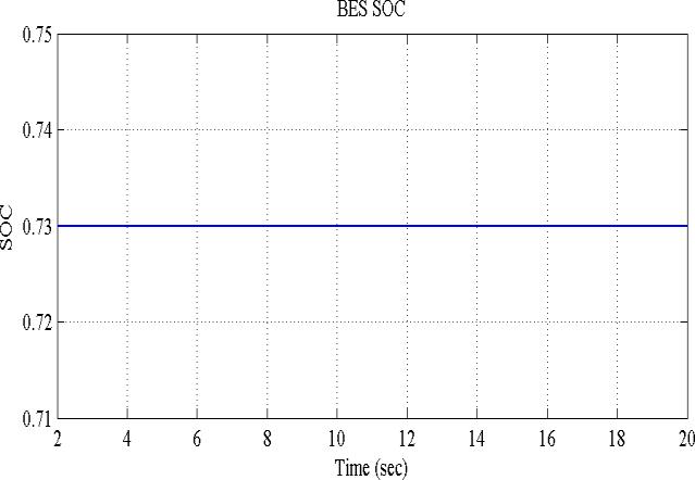
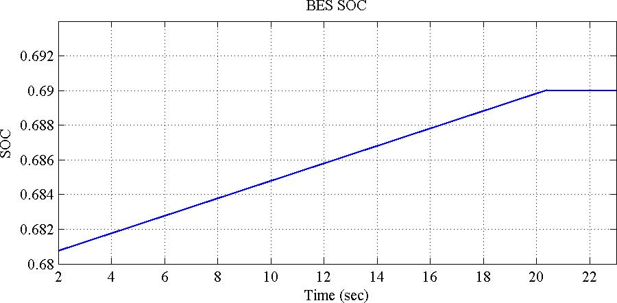
Figure6(b)BatteryischargingundertheSOCcontrol schemetillitreachesthepre specifiedrange, 4. RESULT
Figure 7 Show the microgrid model of the system with 1mw solar plant , BESS controller and power grid. All the outputcanbeseeninScopeofthesystem.
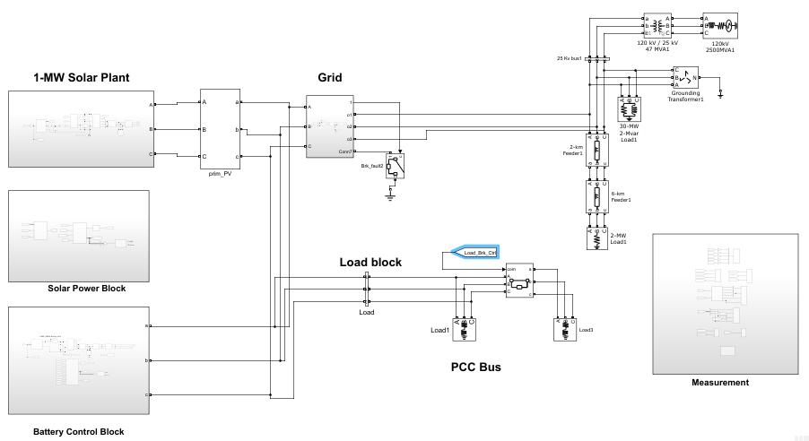
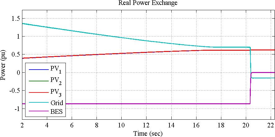
Figure6(a)RealpowerofthethreeSolar PVsystems,the utilitygrid,andtheBESSwhenthebatteryisunderthe chargingmode(pu)
Only the voltage between the terminals of the battery is selected due to it has been modelled as a controllable voltagesource.Hencethevalueissetupto������ ��=800V, that is according to the power range that the converter is operating on.Forthe VSCconverterofthebatterysystem the values for the inductance equivalent resistances are also����=0,5��andtheinductancesvaluesare����=5,4���� The active power reference values will depend on the
International Research Journal of Engineering and Technology (IRJET) e ISSN: 2395 0056
Volume: 09 Issue: 07 | July 2022 www.irjet.net p ISSN: 2395 0072
function of the battery and will be described for each simulation.
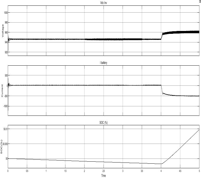
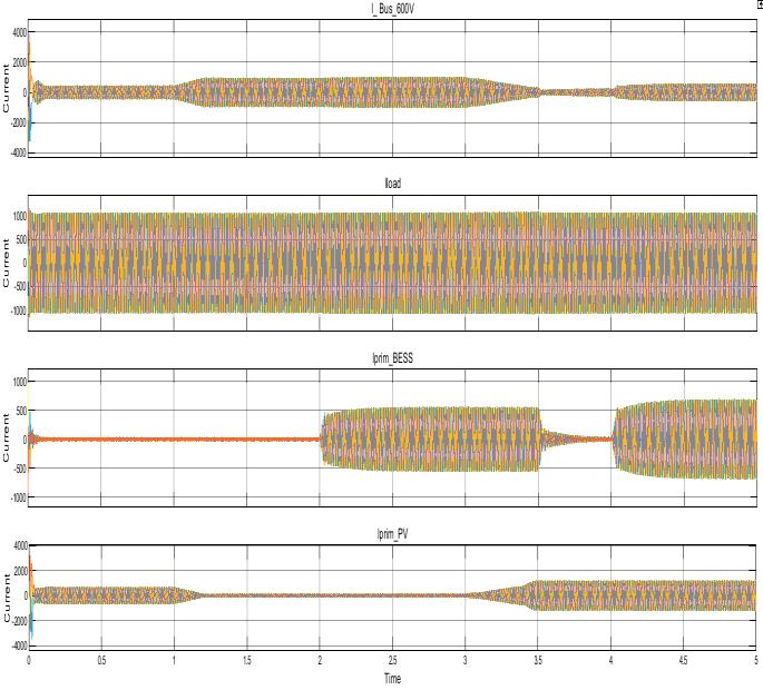
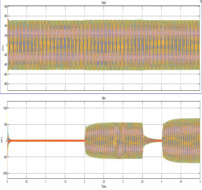
Figure9Voltage,currentandSOCofthebattery.
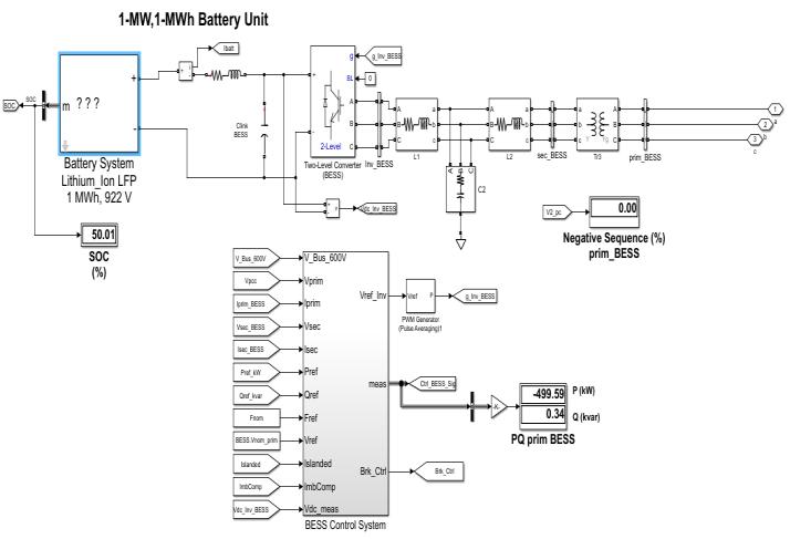
Figure10Voltage,currentOfBESSinverterOutput
Figure11Showsoverallworkingofthesystemalongwith load Current remain constant . to maintain this system, compensate the error by taking current in account using fromavailablesourceofthesystem.
Figure11CurrentVariationofsystemSolar,grid,BESSto maintainloadcurrent.
2022, IRJET | Impact Factor value: 7.529 | ISO 9001:2008 Certified Journal
International Research Journal of Engineering and Technology (IRJET) e ISSN: 2395 0056
Volume: 09 Issue: 07 | July 2022 www.irjet.net p ISSN: 2395 0072
This Paper proposes a control strategy for a microgrid system integrated with multiple Solar PV units and BESS when it is disconnected from the utility grid. The control strategy enables the transfer from the grid connected mode to the islanded mode, assigns the BESS to maintain the voltage and frequency of the islanded microgrid and reconnectstotheutilitygrid.
[1] N. Hatziargyriou, H. Asano, R. Iravani and C. Marnay, "Microgrids," in IEEE Power and Energy Magazine,vol.5,no.4,pp.78 94,July Aug.2007.
[2] Global Market Outlook for Photovoltaics 2014 2018 (EPIA, 2014)& Global Market Outlook for Solar Power2015 2019(SSE,2014).
[3] David Wenzhong Gao, " Energy Storage for SustainableMicrogrid,"Chapter2, Elsevier Ltd,2015.
[4] N. D. Hatziargyriou and A. P. Sakis Meliopoulos, "Distributed energy sources: technical challenges," 2002 IEEE Power Engineering Society Winter Meeting. Conference Proceedings (Cat. No.02CH37309), 2002, pp.1017 1022vol.2.
[5] D. Olivares, A. Mehrizi Sani, A. Etemadi, C. Canizares, R. Iravani, M. Kazerani, A. Hajimiragha,O. Gomis Bellmunt, M. Saeedifard, R. Palma Behnke, G. Jimenez Estevez, and N. Hatziargyriou, "Trends in Microgridcontrol,"IEEETrans.SmartGrid,vol.5,no.4, pp.1905 1919,Jul.2014.
[6] F. Katiraei and J. R. Aguero, "Solar PV Integration Challenges,"inIEEEPowerandEnergyMagazine,vol.9, no.3,pp.62 71,May June2011.
[7] J. A. P. Lopes, C. L. Moreira and A. G. Madureira, "Defining control strategies for Microgrids islanded operation," in IEEE Transactions on Power Systems, vol.21,no.2,pp.916 924,May2006.
[8] X.Chen,Y.Hou,S.C.Tan,C.K.LeeandS.Y.R.Hui, "Mitigating Voltage and Frequency Fluctuation in Microgrids Using Electric Springs," in IEEE Transactions on Smart Grid, vol. 6, no. 2,pp. 508 515, March2015.
[9] L. Xu, Z. Miao and L. Fan, "Control of a Battery system to improve operation of a microgrid," 2012 IEEE Power and Energy Society General Meeting, San Diego,CA,2012,pp.1 8.
[10] I. Serban and C. Marinescu, "Control Strategy of Three Phase Battery Energy Storage Systems for Frequency Support in Microgrids and with Uninterrupted Supply of Local Loads," in IEEE Transactions on Power Electronics, vol. 29, no. 9, pp. 5010 5020,Sept.2014.
[11] Marc Beaudin, Hamidreza Zareipour, Anthony Schellenberglabe, William Rosehart, "Energy storage for mitigating the variability of renewable electricity sources: An updated review", Energy for Sustainable Development,Volume14,Issue4,December2010.
[12] S. Teleke, M. E. Baran, S. Bhattacharya and A. Q. Huang, "Rule Based Control of Battery Energy Storage for Dispatching Intermittent Renewable Sources," in IEEE Transactions on Sustainable Energy, vol. 1, no. 3, pp.117 124,Oct.2010.
[13] Z. Miao, L. Xu, V. R. Disfani and L. Fan, "An SOC Based Battery Management System for Microgrids," in IEEE Transactions on Smart Grid, vol. 5, no. 2, pp. 966 973, March 2014. doi: 10.1109/TSG.2013.2279638.
[14] Abigail Susan Hayhoe, "Impact of Irradiance Change on MPPT and Flicker Phenomenon of Solar PV Systems," Master’s thesis, University of Toronto,2016.
[15] Frank Hohlbaum, Markus Braendle, and Fernando Alvarez, "Cyber Security Practical considerations for implementing IEC 62351," ABB Switzerland,frank.hohlbaum@ch.abb.com
[16] IEEE Guide for Planning DC Links Terminating at ACLocationsHavingLowShort CircuitCapacities,IEEE Std1204 1997.
[17] R. A. Kordkheili, B. Bak Jensen, J. R Pillai and P. Mahat, "Determining maximum photovoltaic penetration in a distribution grid considering grid operation limits," 2014 IEEE PES General Meeting| Conference & Exposition, National Harbor, MD, 2014, pp.1 5.
[18] IEC 60904 3:2016 RLV Redline Version Photovoltaic devices Part 3: Measurement principles for terrestrial photovoltaic (PV) solar devices with referencespectralirradiancedata
[19] https://hvdc.ca/uploads/ck/files/reference_mate rial/PSCAD_User_Guide_v4_3_1.pdf
2022, IRJET | Impact Factor value: 7.529 | ISO 9001:2008 Certified Journal
International Research Journal of Engineering and Technology (IRJET) e ISSN: 2395 0056
Volume: 09 Issue: 07 | July 2022 www.irjet.net p ISSN: 2395 0072
[20] A. Yazdani et al., "Modeling Guidelines and a Benchmark for Power System Simulation Studies of Three Phase Single Stage Photovoltaic Systems," in IEEETransactionsonPowerDelivery,vol.26,no.2,pp. 1247 1264,April2011.
[21] Digambar M. Tagare, "Photovoltaic Energy Solar Cells and Solar Power Systems," in ElectricityPower Generation: The Changing Dimensions ,1, Wiley IEEE Press, 2011, pp.195 216 doi: 10.1002/9780470872659.ch10
[22] M. G. Villalva, J. R. Gazoli, and E. R. Filho, "Comprehensive Approach to Modeling and Simulation ofPhotovoltaicArrays,"inIEEETransactionson Power Electronics,vol.24,no.5,pp.1198 1208,May2009.
[23] E. Muljadi, M. Singh, and V. Gevorgian, " PSCAD Modules Representing PV Generator, "National Renewable Energy Laboratory, Technical ReportAugust2013.
[24] Ned Mohan, Tore M. Undeland, and William P. Robbins, " Power Electronics Converters, Applications, andDesign,"Wiley,2003.
2022, IRJET | Impact Factor value: 7.529 | ISO 9001:2008 Certified Journal