International Research Journal of Engineering and Technology (IRJET) e ISSN: 2395 0056

Volume: 09 Issue: 07 | July 2022 www.irjet.net p ISSN: 2395 0072
International Research Journal of Engineering and Technology (IRJET) e ISSN: 2395 0056
Volume: 09 Issue: 07 | July 2022 www.irjet.net p ISSN: 2395 0072
Vedpathak1 , Prof. Ajay Hamane2
1 Student, Department of Civil Engineering, M. S. Bidve Engineering College, Latur, Maharashtra, India
2 Professor, Department of Civil Engineering, M. S. Bidve Engineering College, Latur, Maharashtra, India ***
Abstract Bomb explosion near a building can cause disastrous damage to the building externally and internally. This can cause minor, moderate or major damage to the building. The main aim of this study is to do a comparative analysis of building models and know the response when subjected to blast loads using ETABS software. In this study a 12 storey building is subjected to 100kg and 200kg TNT charge weight with stand of distance 20m and 40m. Blast parameters are calculated using IS 4991 1968.Further four models are considered by implementing different structural systems and response of the models in terms of storey displacement andstorey drift is consideredto knowthe model with the structuralelement that helps resist the effect ofblast.
Key Words: Analysis, ETABS, Blast, Storey Displacement, Storey Drift
Structures,majorlythathavehigherchancesofbeingtarget ofterroristattacksshouldbesafefromtheblasteffects.Itis importanttostudyaccordinglyintothisareatoreducethe lossescausedduetotheblasteffectsonthebuildings.The dynamic replica of the structure to blast loading is complicatedtoanalysebecauseofthenon linearactionof material. Blast explosions result in voluminous dynamic loads,morecomplex thantheoriginal designloads,so for analysisanddesignofblastloadingdetailedknowledge is required of blast and its phenomena. Due to increase in technology, the buildings mostly in large cities are concentratedmuchonthecomfortoflivingandthesafety against earthquake and wind loads but not concentrated much on the blast loads. As explosions are becoming commoninmetropolitancitiesconsiderationofblastloads ontallbuildingsespeciallypublicandcommercialbuildings is necessary. In blast analysis, one can determine the acceptabledamagelevelthatastructurecangothroughand designed accordingly so that the structure can manage to withstandevenunderworstconditions.Whentheexplosion occurs, the damage can occur directly or indirectly, externallyorinternallyandsoitshouldbepossiblysafein alltheways;prediction,preventionandmitigationofsuch eventsareofmajorconcern.Thisstudyreferstotheanalysis of the building under blast load and its impact on the structureinresponsetostoreydisplacementandstoreydrift fordifferentmodelsimplementedwithdifferentstructural elements.Themodelsareanalysedandcomparedtoknow theblastresistantbuildingmodeltopreventoverallcollapse
ofthebuildinginreferencetothestoreydisplacementand storeydrift
1.1
•
The explosion that occurs in open air causes a wave that spreads from the source of detonation to the structure without any wave amplification, as the explosion is at a certaindistanceandheightofstructurethewaveincreases due to the reflection of ground before it contacts the structure.
Theexplosionnearthegroundisanexplosionoccurringnear or on the ground and the initial pressure is immediately increasedasaresultofrefractionontheground.
•
If the explosion occurs inside the structure, the peak pressures associated with the initial wave fronts are extremelyhigh.Theyareenhancedbytherefractionwithin thestructure.Inadditiontothis,dependingonthedegreeof confinement, high temperatures and the accumulation of gaseous products of chemical reactions in the blast would producemorepressureandincreasetheloaddurationwithin thestructure.Thecombinedeffectsofthesepressurescan lead to the collapse of the structure, if the structure is not designedtowithstandinternalpressure.Effectofpressureis differentinstructureswithopeningsandstructureswithout openings.
•Minor:
o Non structural failure of building elements such windows,doors
o Injuries may be expected and deaths are possible butunlikely.
•Moderate:
o Structural damage is confined to a localized area andisusuallyrepairable.
o Structuralfailureislimitedtosecondarystructural members, such as beams, slabs and non load bearingwalls.
International Research Journal of Engineering and Technology (IRJET) e ISSN: 2395 0056
Volume: 09 Issue: 07 | July 2022 www.irjet.net p ISSN: 2395 0072
o Injuriesanddeathsareexpected.
•Major:
o Loss of primary structural members such as columns.
o Inthiscase,extensivedeathsareexpected.
o Buildingbecomesnonrepairable.
theenergyreleasedduringtheblast,distancebetweenthe detonationpointandthestructurecalledasstandoffdistance andintensityofthepressurereleased.
The IS Code 4991 1968 appendix C gives the general recommendationsforplanningblastresistantbuildings.
•Sizeofrooms:smallsizeofroomsgenerallyconfinesthe blastdamagetoalimitedareaofthestructure,becauseofthe screeningactionofthepartitionwalls.
Toresistorsurviveterroristattacks.
Tominimizedamagetotheassets.
Tominimizethelossoflives.
Tosubsidesocialpanic.
Toprotectthehistoricalmonumentsandimportant buildings.
The term blast is used commonly to describe situation in which rapid release of energy occurs from a chemical, mechanicalornuclearsource.Structuresdesignedtoresist blastloadaresubjectedtocompletelydifferenttypeofload thanconsideredinregulardesign.Heretheyarehitwitha rapidlymovingshockwavewhichmayexertpressuremany timesgreaterthanthoseexperiencedunderstorms.Ablast loadistheloadappliedtoastructureorobjectfromablast wave,whichisdescribedbythecombinationofoverpressure thatistheriseinpressureaboveatmosphericpressuredueto the shock wave from an air blast, and either impulse or duration that causes catastrophic damage to the building both externally and internally. Blast effect is the damage caused by the force of an explosive blast. When the blast occursatalocationtherewillbeahugeamountofhotgases releasedwhichisthecompressesthesurroundinggasesand travelsawayfromtheblastsourcewithhighervelocity.The distancebetweentheblastsourcepointandthestructureis calledasthestandoffdistance.Astheblastwavetravelsaway from the blast source the pressure or the intensity of the wave goes on reducing and due to this the effect on the building with higher standoff distance will be less and the timedurationrequiredtoreachthebuildingisreduced.the blast wave propagation curves depending on the pressure anddistancefromtheexplosionortheblastsource.Ablast wave generated during an explosion spreads through the surroundingairandduetowhichashock frontorwaveis created. This shock wave created surround the entire building subjected to blast pressure. Due to the impulsive loaddevelopedbyanexplosionishighlynonlinearandcause pressure in an extremely short duration, analysis of the reinforced concrete frame structure is difficult. Pressure intensitieswillbedependeduponthechargeweight(bomb size) and standoff distances between blast source and impacted structure (target).The factors affecting the blast loadarethematerialtype,weightoftheexplosive,amountof
•Corridors:longnarrowcorridorsshouldbeavoidedas theytendtoincreasetheextentofdamagealongthelengthof thecorridorsbecauseof‘multiplereflections.
•Projections: all slender projections like, parapets and balconiesspeciallythosemadeofbrittlematerialsshouldbe avoidedasfaraspossible.
•Chimneys:masonrychimneysonfactorybuildingsand boilerhousesareapotentialhazardandshouldbeavoided.
•Roofingandcladdingmaterials:brittleroofingmaterials, suchastilesandcorrugatedasbestossheetsareespecially prone to blast damage. When corrugated galvanized iron sheets are used for roofing and/or cladding, particular attention should be paid to the fixtures fastening the corrugatedgalvanizedironsheetstotheframework.
•Useoftimberandotherinflammablematerials:theseare especiallypronetocatchfireinastrafingorincendiaryattack andshouldbebestavoidedinstrategicstructureswheresuch attacksmightbeexpected.
•Electric wiring: conduit wiring is preferable to open wiring,asincaseoflargemovementofthewallstheconduit willgiveanaddedprotectiontothewiringinsideandprevent them from getting cut thus preventing fire hazards due to shortcircuits.
•Glasspanes:themostwidespreaddamageduetoblastis the breaking of glass panes. The splinters from shattered glass window are dangerous to personnel safety. It is preferabletousenon splinteringtypeglasspaneswherever theirusecannotbeavoided.
•Doors:doorsshouldbedesignedforthefrontfaceload. Wall thicknesses against flying splinters for protection againstsplintersfrombombswithequivalentbarecharges explodingatadistanceof15m,thewallthicknessesgivenin table8willbeadequate.
According to the IS Code 4991 1968: Criteria for blast resistantdesignofstructureforexplosionsabovegrounduse
International Research Journal of Engineering and Technology (IRJET) e ISSN: 2395 0056
Volume: 09 Issue: 07 | July 2022 www.irjet.net p ISSN: 2395 0072
ofTNT(Trinitrotoluene)whichisapaleyellow,solidorganic nitrogen compound used chiefly as an explosive, is considered as a reference for determining the blast parameters for different charge weights and standoff distances.Theblastparameterscalculatedforthestudyare inthesimilarwayasshownintheexampleintheISCode.
ExamplefromISCode4991 1968,appendixAforcalculation of blast parameters for the rectangular building above ground
Blast parameters due to the detonation of a O.1 tonne explosive are evaluated on an above ground rectangular structure,3mhigh,10mwideand8mlong,situatedat30m fromgroundzero.
Scaleddistancex=30/(0.1)1/3=64.65m
From Table 1 of IS Code assuming pa = 1.00 kg/cm2 and linearlyinterpolatingbetween63mand66mforthescaled distance64.65m,thepressuresaredirectlyobtained:
Pso=0.35kg/cm2;Pro=0.81kg/cm2;qo=0.042kg/cm2
ThescaledtimestoandtdobtainedfromTable1ofISCode forscaleddistance64.65maremultipliedby(0.1)1/3toget thevaluesoftherespectivequantitiesfortheactualexplosion of0.1tonnecharge.
to=37.71(0.1)1/3=17.5milliseconds;td=28.32(0.1)1/3= 13.15milliseconds
M= 1+6pso/7pa=1.14 a = 344 m/s; U = 1.14 * 344 = 392 m/s = 0.392 m/millisecond
b)PressuresontheBuilding: HereH=3m,B=10m,andL=8m ThenS=3m
tc=3S/U=3x3/0.392=23.0milliseconds>td tt=L/U=8/0.392=20.4milliseconds>td tr=4S/U=4*3/0.392=30.6milliseconds>td Astr>tdnopressureonthebackfaceareconsidered.
ForFrontFace: Pro=0.81kg/cm2
Forroofandsides: Cd= 0.4;pso+Cd*qo=0.35 0.4*0.042=0.33kg/cm2 Here, 0.1 Tonne TNT Explosive is considered for standoff distance30m
pa = ambient atmospheric pressure; pso= peak side-on overpressure
pro= peak reflected overpressure; qo = peak dynamic pressure
to = positive phase duration; td = duration of equivalent triangularpulse
M =machno.= 1+6pso/7pa a =velocityofsoundinair U =shockfrontvelocity=M*a S =HorB/2whicheverisless. Cd=dragcoefficient,consideredfromtable2ofISCode.
ETABSsoftwareisusedinthisstudy.A12 storeystructureis consideredsubjectedto100kgand200kgchargeweightfor differentstandoffdistancesof20mand40mforeachcharge weight.Deadload,liveloadandblastloadareconsideredfor theanalysis.Fourcasesareconsideredcorrespondingtothe chargeweightsandstandoffdistancesrespectively.All the blastparametersarecalculatedusingtheISCode4991 1968 forthefourcases.Thepeakreflectedoverpressureobtained forthefrontandsidefaceofthestructureismultipliedwith thetributaryareaofthejointandblastloadiscalculated.The calculated blast load is applied as the joint load on all the storeysofthestructureandanalysisisdoneusingsoftware. Responseofthestructuresforfourcasesintermsofstorey displacementandstoreydriftareobserved.Forfurtherstudy, four models are generated; the structure among the four cases that shows maximum displacement and drift is considered as first model and other three models are generated with different structural elements respectively. Now all the four models are analyzed in the software to observe the response of models in terms of storey displacementandstoreydrifttoconcludebyanalyzingthe modelthatismoreresistanttoblastload.
Cases considered for analysis:
Case 1: Blast of 100kg explosive with standoff distance of 20m
Case 2: Blast of 100kg explosive with standoff distance of 40m
Case 3: Blast of 200kg explosive with standoff distance of 20m
Case 4: Blast of 200kg explosive with standoff distance of 40m
Four different models generated for analysis:
Model1 NormalBuildingStructure
Model2 BuildingStructurewithincreasedcolumn&beam sizes.
2022, IRJET | Impact Factor value: 7.529 | ISO 9001:2008 Certified Journal
International Research Journal of Engineering and Technology (IRJET) e ISSN: 2395 0056
Volume: 09 Issue: 07 | July 2022 www.irjet.net p ISSN: 2395 0072
Model3 BuildingStructurewithadditionofshearwallsat thecorners.
Model4 BuildingStructurewithadditionofsteelbracingat thecorners.
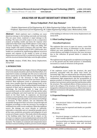
Noofgridinxdirection 5
Noofgridinydirection 4
Spacingofgridinxdirection 5
Spacingofgridinydirection 4
Noofstorey 12
Storeyheight 3m
Bottomstoreyheight 3m
Sizeofcolumn 400*400mm
Sizeofbeam 300*300mm
Thicknessofslab 150mm
LiveLoad 3kn/m2
BrickMasonryexternalwall 0.230m
BrickMasonryinternalwall 0.115m
Fig 1:Planviewofbuilding.
BlastParameters Case1 Case2 Case3 Case4
Blast(kg) 100 100 200 200 Standoffdistance(m) 20 40 20 40 Scaleddistance(m) 43.08 86.17 34.19 68.39 pa(kg/cm2) 1 1 1 1 pso(kg/cm2) 0.724 0.232 1.120 0.324 pro(kg/cm2) 1.858 0.508 2.981 0.730 qo(kg/cm2) 0.170 0.018 0.388 0.035 to(milliseconds) 13.915 19.820 14.99 22.602 td(milliseconds) 9.626 14.940 9.91 17.047
M 1.26 1.095 1.39 1.132 a(m/s) 344 344 344 344 U 0.433 0.376 0.478 0.389 B 12 12 12 12 L 20 20 20 20
S 6 6 6 6
tc 41.57 47.87 37.65 46.27 tt 46.18 53.19 41.84 51.41 tr 55.42 63.82 50.20 61.69
Cd 0.4 0.4 0.4 0.4
FrontFacePressure 1.858 0.508 2.981 0.730
SideFacePressure 0.656 0.224 0.964 0.31
Loadsonfrontfacejointsofthestructurex direction(KN)
Loadonsidejoints 675 187.5 1087.5 270
Loadonedgejoints 1350 375 2175 540
Loadoncentrejoints 2700 750 4350 1080
Loadsonsidefacejointsofthestructurey direction(KN) Loadonsidejoints 540 150 870 216
Loadonedgejoints 1080 300 1740 432 Loadoncentrejoints 2160 600 3480 864
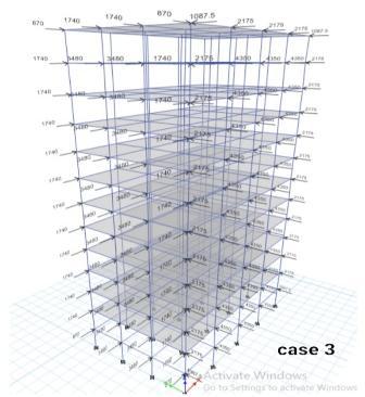
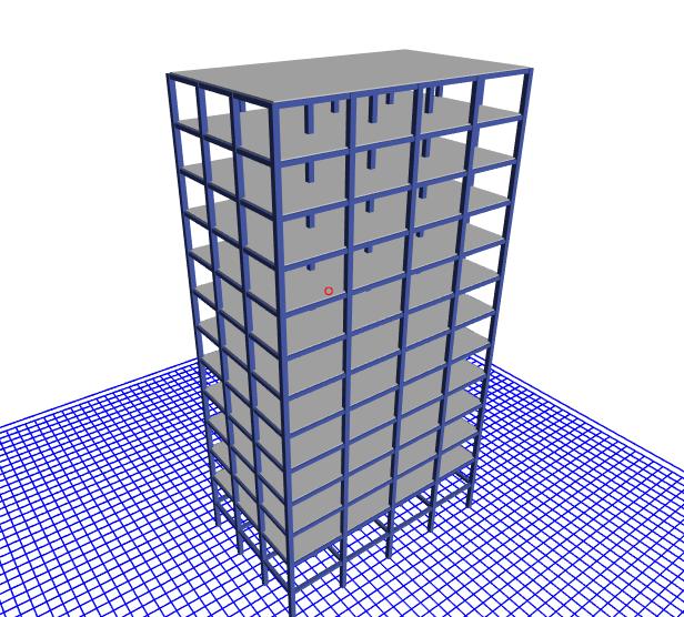
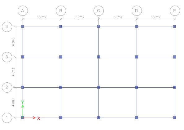
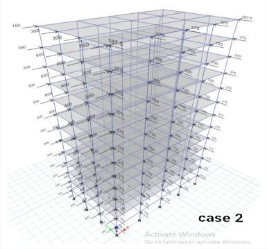
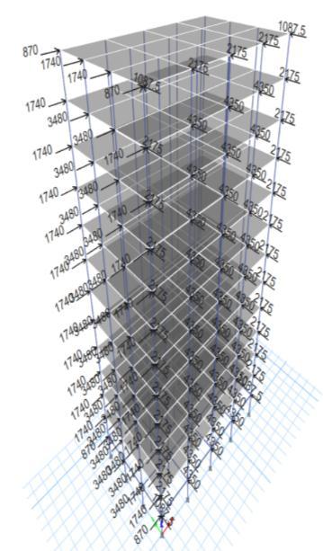
Fig 2:3Dviewofbuilding.
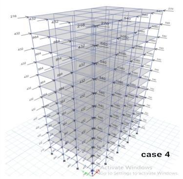
Fig 3:Loadapplicationonbuildingforfourcases.
International Research Journal of Engineering and Technology (IRJET) e ISSN: 2395 0056
Volume: 09 Issue: 07 | July 2022 www.irjet.net p ISSN: 2395 0072
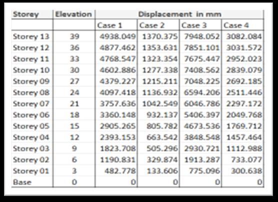
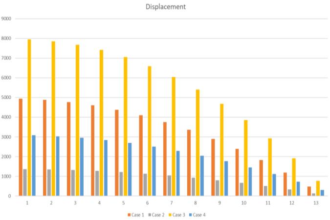
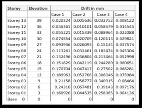
Fig -4: Displacementcomparisonforfourcases
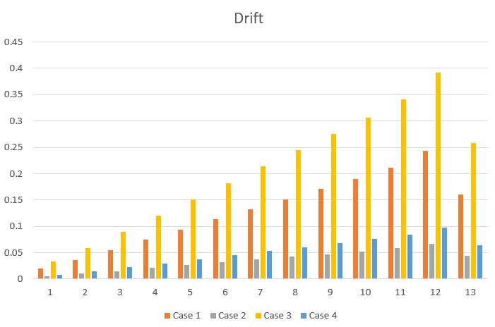
Fig 7: Driftcomparisonforfourcases
Model 1: Amongthefourcasesanalyzedthecase3hasthe maximumdisplacementanddrift.Itshowsthatforincrease inblastloadanddecreaseinstandoffdistance,displacement and drift increases drastically. For further study case 3 is considered as model 1 and response in terms of storey displacementandstoreydriftisobserved.
Fig 5: Displacementcomparisonforfourcases
Model 2: Forcreatingthemodel2,themodel1isconsidered andchangesaredoneintermsofcolumnsandbeamsofthe structurefor the similar blastload.Column isa structural elementthattransmits,throughcompression,theweightof thestructureabovetotheotherstructuralelementsbelow. Beam is a horizontal member spanning an opening and carryingaloadthatmaybeabrickorstonewallabovethe opening. For this model the column and beam sizes are increased. Column size is changed from 400x400 mm to 600x600 mm. Beam size is changed from300x300 mm to 450x450mm.Themodelisthenanalyzedandresponsein termsofstoreydisplacementandstoreydriftisobserved.
Model 3: Forcreatingthemodel3,themodel1isconsidered andchangesaredoneintermsofaddingshearwalltothe structureforthesimilarblastload.Shearwallisstructural element that is a rigid vertical diaphragm capable of transferring lateral forces from exterior walls, floors and roofstothegroundfoundationinadirectionparalleltotheir planes,it resists theforces suchaswind, seismicandalso blast.Forthismodelshearwallsareaddedatthecornersof thestructure,thethicknessoftheshearwallisconsideredas 150mm.Themodelisthenanalyzedandresponseinterms ofstoreydisplacementandstoreydriftisobserved.
Fig 6: Driftcomparisonforfourcases
Model 4: Forcreatingthemodel4,themodel1isconsidered and changes are done in terms of adding bracings to the structureforthesimilarblastload.Bracingsarestructural elementsthatprovidestabilityandresistsloads,theyconsist ofdevicesthatclamppartsofstructuretogetherinorderto strengthenorsupportit,itresiststheforcessuchaswind, seismicandalsoblast.Forthismodelbracingsareaddedat
International Research Journal of Engineering and Technology (IRJET) e ISSN: 2395 0056
Volume: 09 Issue: 07 | July 2022 www.irjet.net p ISSN: 2395 0072
thecornersofthestructure,X steelbracings,ISWB500are considered. The model is then analyzed and response in termsofstoreydisplacementandstoreydriftisobserved. Fig 7: Model1 Fig 8: Model2 Fig 9: Model3 Fig 10: Model4
The aim of blast resistant building study is to prevent the overallcollapseofthebuildingandpreventmoredamageto the building. In spite of the fact that the extent of the explosion and the loads cannot be predicted perfectly or accurately.Themostpossibleactionsandconsiderationswill helptofindthenecessaryengineeringsolutionsforit.
Inthisstudythescenarioconsideredaretheresponse for assumed blast on the structure in terms of storey displacementandstoreydrift.
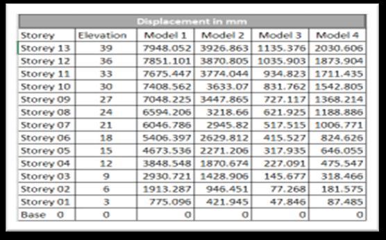
Storey Displacement: It is the total displacement of the storeywithrespecttoground.
StoreyDrift:Itisthelateraldisplacementofafloorrelative tothefloorbelow.
8000
6000
4000
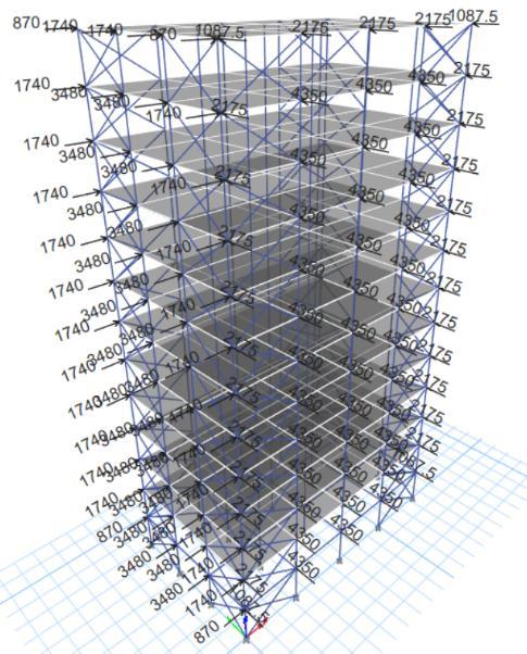
Fig -11: Displacementcomparisonforfourmodels 0
10000 1 2 3 4 5 6 7 8 9 10 11 12 13
2000
Model 1 Model 2 Model 3 Model 4
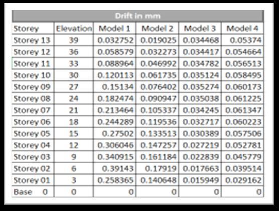
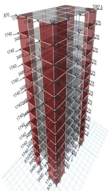
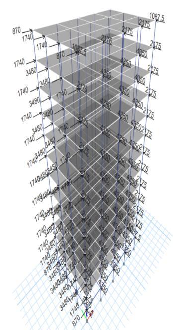
Fig 12: Displacementcomparisonforfourmodels
Fig 12: Driftcomparisonforfourmodels
International Research Journal of Engineering and Technology (IRJET) e ISSN: 2395 0056
Volume: 09 Issue: 07 | July 2022 www.irjet.net p ISSN: 2395 0072
It is observed that adding shear wall and steel bracingsgiveeffectiveresultsandshowsdecrease inthestoreydisplacementandstoreydrift.Butitis clearly observed that the addition of shear walls give the good results and show minimum storey displacement and storey drift in the structure comparedtotheothermodels.
[1] M. J. Sonavne, To Study And Analysis of RCC StructureUnderBlastLoadingbyJournalOfApplied ScienceAndComputations(2019)1076 5131
[2] P. Srikant Reddy, Blast Resistant Analysis And DesignTechniquesForRCCMultistoreyBuildingBy International Journal Of Civil Engineering And Technology(2018)0976 6308
From the four cases studied, it shows that as the blast load increases and the standoff distance decreases the storey displacements and storey driftsincreasedrastically.
Theblastparametersandeffectofblastdependson thechargeweightandstandoffdistancevalues.
From the models studied, it shows remarkable changeinthestoreydisplacementandstoreydrift, duetoaddingofdifferentstructuralelements,there isreductioninthestoreydisplacementandstorey drift
Inthemodel2,wherecolumnandbeamsizesare increased, the results show that structure will improvetheresistance,butashugecrosssectionof columnsandbeamsisneededitwillnotbepossible inmanycircumstances.
Inthemodel3,wheretheshearwallsareaddedat the corners of the structure, the results show effectiveimprovementintheresistanceandcanbe consideredforthestructuretobedesignedforblast resistance.
Inthemodel4,wherethesteelbracingsareadded at the corners of the structure, the results show improvement in the resistance and can be consideredforthestructuretobedesignedforblast resistance.
[3] ShobhaR,ResponseOfTallStructuresAlongFace ExposedToBlastLoadAppliedAtVaryingDistance ByInternationalJournalOfRecentTechnologyAnd Engineering(2020)2277 3878
[4] T.P.Nguyen,ResponseOfVerticalWallStructures UnderBlastLoadingByDynamicAnalysis,Procedia Engineering14(2011)3308 3316
[5] C. M. Deshmukh, Behavior Of RCC Structural Members For Blast Analysis: A Review By InternationalJournalOfEngineeringResearchAnd Application(2016)2248 9622
[6] M.Meghanadh,BlastAnalysisAndBlastResistant Design Of R.C.C Residential Building By International Journal Of Civil Engineering And Technology(2017)0976 6308
[7] Sana N. Kazi, Analysis Of Blast Resistant RCC Structure By International Research Journal Of EngineeringAndTechnology(2017)2395 0056
[8] SajalVerma,BlastResistantDesignOfStructureBy International Journal Of Research In Engineering AndTechnology(2015)2319 1163