International Research Journal of Engineering and Technology (IRJET) e ISSN: 2395 0056

Volume: 09 Issue: 07 | July 2022 www.irjet.net p ISSN: 2395 0072
International Research Journal of Engineering and Technology (IRJET) e ISSN: 2395 0056
Volume: 09 Issue: 07 | July 2022 www.irjet.net p ISSN: 2395 0072
2
1Post Graduate Student in Civil Engineering, MGM’s College of Engineering and Technology, Kamothe, India. 2Professor, Dept. of Civil Engineering, MGM’s College of Engineering and Technology, Kamothe, India. ***
Abstract It has been widely known that outrigger beams/truss are generally appropriate for resistance against eminent wind loads, but incorporating outriggers for earthquake resistance has been intriguing area for research. In the past many researchers have analyzed the effects of featuring outriggers with various configurations in the high rise building in frames with different loading condition in order to reduce and control the deflections and stresses. However, the performance of various other possible outrigger systems under seismic loads has not been studied extensively for commercial high rise structures. In this paper the feasibility of various Outrigger Structural Systems for Commercial High rise structures under Seismic load is studied. This includes linear methods of analysis, namely Response Spectrum Analysis and Equivalent Static Load Method. It is concluded that the two outriggers with belt truss combination offers maximum reduction in deflection of 18%.
Key Words: High Rise Buildings, seismic loads, outrigger systems,belttrusssystems,linearanalysis
In modern tall buildings, lateral loads induced by wind or earthquakeareoftenresistedbyasystemofcoupledshear walls.Thedesignofskyscrapersisusuallygovernedbythe lateral loads imposed on the structure. More specifically the design of tall and slender structures is controlled by three governing factors, strength (material capacity), stiffness (drift) and serviceability (motion perception and accelerations), produced by the action of lateral loading, such as wind. The overall geometry of a building often dictates which factor governs the overall design. As a buildingbecomestallerandslenderer,driftconsiderations becomemoresignificant.Proportioningmemberefficiency based on maximum lateral displacement supersedes design based on allowable stress criteria. Through the designofahigh risestructure,numerousproblemsappear such as the number of columns or size and shape of concrete core or even basic dimensions of the structure itself. Having constraints for the building immediately defines and solves part of the unknown variables but it is the geometry of the structural system inside these basic parameters that identifies an efficient design. Undoubtedly, the factor that governs the design for a tall and slender structure most of the times is not the fully
stressed state but the drift of the building. There are numerous structural lateral systems used in high rise building design such as: shear frames, shear trusses, frameswithshearcore,framedtubes,trussedtubes,super frames etc. However, the outriggers and belt trusses systemistheoneprovidingsignificantdriftcontrolforthe building.
Many researchers have analysed the effects of featuring outriggers with various configurations in the high rise building in frames with different loading conditions in order to reduce and control the deflections and stresses. Akash Kala et. al. studied the optimum position of outrigger with belt truss in tall building under horizontal load. The main aim of this study is to study the use of outrigger and belt truss placed at different location subjectedtowindloads.Thestudyconcludedtheoptimum outrigger location of high rise building under action of windloadisbetween0.25 0.33timestheheightofbuilding (from bottom of building) [1]. Akshay Khanorkar et. al. reviewedvariousparameterssuchaslateraldisplacement, storeydrift,coremomentandoptimumpositionrelatedto outrigger and belt truss for controlling deflections in tall buildings. The concluded Optimum position of structural system for deflection criteria is different than bending moment criteria [2] Suresh and Pradeep K.M. analysed the effect and performance of outrigger in 30 storey building provided different levels along the building height by varying relative stiffness. They concluded the percentage reduction of lateral displacement and inner storeydriftwithrespecttobareframevariesfordifferent model configuration for different seismic zone and the maximuminnerstoreydriftisobservedatbuildingheight in range of 5 15m [3]. Mohd Abdus Sattar et. al. studied the effect of building displacements in lateral direction with shear core, outrigger and belt truss. They concluded that floor rigidity is not required to be increased beyond that required for the load carrying of Dead load and Live load on floors. Column forces and moments are minimum in case of “Building frame with Double Core arrangement of shear wall and Stringer beams” for which drift and displacement are also comparatively less. Moments in Corner column are less compared to the middle column. Momentsinouterperipherycolumnsarelesscomparedto themomentsininteriorcolumns[4]. Kiran Kamath et. al.
International Research Journal of Engineering and Technology (IRJET) e ISSN: 2395 0056
studied the performance of multi outrigger based on location of outrigger and also performance in term of lateral displacement in top, storey drift, shear force and bending moment in core wall based on relative axial rigidity.Theyfoundthemaximumpercentageofreduction inbendingmomentachievedwhenoutriggerswereplaced betweentopand67%oftotalheightwhencomparedwith modelwithoutoutrigger[5].
InthispaperthefeasibilityofvariousOutriggerStructural Systems for Commercial High rise structures under Seismic load is studied. This includes linear methods of analysis, namely Response Spectrum Analysis and EquivalentStaticLoadMethod.
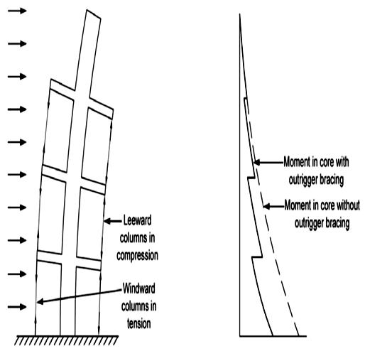
Fordesignoftallstructures,theuseofcore wallsystem has been a very effective and efficient structural system usedinreducingthedriftduetolateral load.However, as and when the height of the building increases, the core does not have the adequate stiffness to keep the drift down to acceptable limits. For such high rise structures, horizontal structural systems known as outriggers are introduced. The layout of an outrigger in a building is showninfigure1.
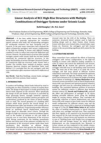
columns.Additionally,byincludingdeepspandrelgirders, which work as belts surrounding the entire building, it is possible to mobilize also the other peripheral columns to assist in restraining the outriggers, providing an improvementupto25 30percentinstiffness.Inorderto have the outrigger and belt girder adequately stiff in flexure and shear, they often present a vertical extension which covers at least one or two storey. Figure 2 shows the structural behaviour and mechanics of buildings with andwithoutoutriggers.
Fig - 1 Layoutofconventionalofoutriggersintall buildings[2]
Outriggersareprimarilyconceivedtoreducetheglobal deformation of the building, caused by the flexural behaviour of the resistant core. This is achieved by reducing the overturning moment of the cantilever scheme and by transferring the reduced moment to the outer members through extremely rigid horizontal beams connected to the core at specific levels. These horizontal beams are referred to as outriggers. The efficiency of the outriggersystemdependsupontheflexuralstiffnessofthe girder and the axial stiffness of perimeter vertical
Fig 2 Structuralbehaviourofanoutriggersystemand comparisonofmomentdiagramswithandwithout outriggerbracings[6]
In this study 3D models were prepared using Finite Element based software ETABS. The software is able to run, analysis and obtain results according to Indian Standard Code of practice. The following design criteria wereconsideredformodelingpurposes:
1. A 54 storey building with different outrigger configurations.Themodelsshallbebasedonanactualplan ofacommercialbuilding.
2. Storey height shall be kept constant at 3.9meters forall stories
3. The plan of the structure shall be square in shape with size49.7m.X49.7m.
4. The structure shall be analyzed in Seismic Zone IV and soil type selected shall be Type 1 (Rock and Hard soil) as perIS:1893(part I):2002
Thevariousloadingparametersfordeadload,liveloadand seismicloadsareshowninTables1 3
Volume: 09 Issue: 07 | July 2022 www.irjet.net p ISSN: 2395 0072 © 2021, IRJET | Impact Factor value: 7.529 | ISO 9001:2008 Certified Journal | Page1078
International Research Journal of Engineering and Technology (IRJET) e ISSN: 2395 0056
Volume: 09 Issue: 07 | July 2022 www.irjet.net p ISSN: 2395 0072
UnitweightofConcrete 25kN/m3(forcalculating selfweightofstructure)
Unitweightoffloorfinish 24kN/m3
UnitweightofBrickmasonry walls 20kN/m3
Commercialarea 4.0kN/m2 Staircases 3.0kN/m2
Terrace 2.0kN/m2
Liftmachineroom 10.0kN/m2orasperLift Vendor(whicheverishigher)
Zonefactor(Z) 0.36
Responsereductionfactor 5
Importancefactor 1.5
Frametype SpecialMomentResisting Frame(SMRF)
ThetimeperiodcalculationsisshowninTable 4
With infill panel (with brick wall) Without infill panel (without brick wall) T=0.09 x H/D0.5 T=0.075 x H0.75
Where, T=timeperiodinsecond, H=totalbuildingheightfrombottomtoterracelevel D=x&yDimensionofthebuilding
WindloadsarecalculatedasperIS:875(Part3)usingthe followingparameters:
Basic wind speed (Vb) =44m/sec
Design Wind Speed (Vz) =Vb*k1*k2*k3
Where, k1=Probabilityfactor=1 k2=Terrain,heightandstructuresizefactor k3=Topographyfactor(Class:C) (TerrainCategory:2)
Design wind pressure (Pz) =26.0z
Following load combinations are considered for calculating the forces at ultimate limit states as per IS: 875 1987(Part V)andIS:1893 2002(Part I)
•1.5DL+1.5LL
•1.2DL+1.2LL±1.2EQX 1.2DL+1.2LL±1.2EQY
•1.5DL±1.5EQX 1.5DL±1.5EQY
•0.9DL±1.5EQX 0.9DL±1.5EQY
•1.2DL+1.2LL±1.2WLX 1.2DL+1.2LL±1.2WLY •1.5DL±1.5WLX 1.5DL±1.5WLY
•0.9DL±1.5WLX 0.9DL±1.5WLY
Where, DL=DeadLoad EQ=EarthquakeLoad WL=WindLoad LL=LiveLoad
Based on the literature review and the gaps found in the research, the combinations of model for different Outrigger systems are obtained. The various model combinationsareasfollows:
•RCC bare frame with shear core walls (base model for comparison)
•RCC bare frame with shear core and two outriggers (outriggerattop+outriggeratmidheight)
•RCC bare frame with shear core, two outriggers and peripheral belttruss(outriggerattop+outriggerat0.6th height)
•RCC bare frame with shear core and three outriggers (outrigger at top + two equally spaced throughout the height)
In this paper two linear analysis methods have been studied namely Equivalent Static Load Method and ResponseSpectrummethod
AsperIS 1893 2002,themassofthestructuremultiplied by design Equivalent coefficient, acts statically in a horizontal direction. It is also assumed here that the magnitude of the coefficient is uniform for the entire membersofthestructure.Designshearsatdifferentlevels in a building shall be computed from the assumption of linear distribution horizontal accelerations, varying from zeroatthebaseofthestructuretoamaximumatthetop. Thismethodincludesthefollowingdesigncomponents.
a) Design Seismic Base Shear b) Seismic Weight of Building c) Fundamental Natural Time Period
Distribution of Design Force
Detaileddescriptionandformulationfortheabovecan be found in IS 1893(2002) and the same have been used in theETABSsoftware.
© 2021, IRJET | Impact Factor value: 7.529 | ISO 9001:2008 Certified Journal | Page1079
International Research Journal of Engineering and Technology (IRJET) e ISSN: 2395 0056
The response spectrum represents an envelope of upper bound responses, based on several different ground motionrecords.Thismethodisanelasticdynamicanalysis approach that relies on the assumption that dynamic responseofthestructuremaybefoundbyconsideringthe independent response of each natural mode of vibration andthencombiningtheresponseofeachinsameway.
Thismethodincludesfollowingcomponents:
a) Modal mass (Mk)
b) Modal Participation factor (Pk)
c) Design lateral force at each floor in each mode
d) Storey shear forces in each mode
e) Storey shear force due to all modes considered
Detaileddescriptionandformulationfortheabovecan be found in IS 1893(2002) and the same have been used in theETABSsoftware
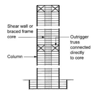
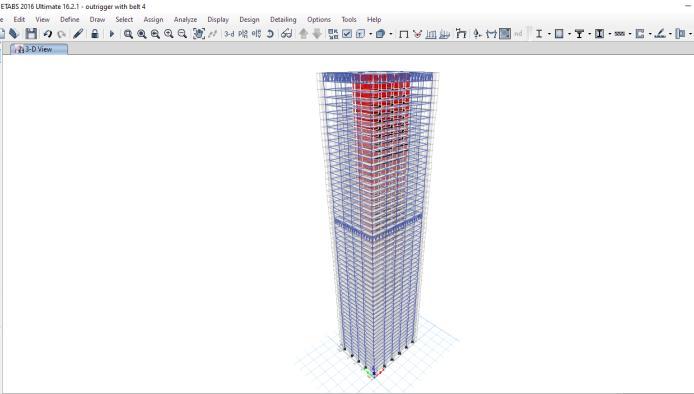
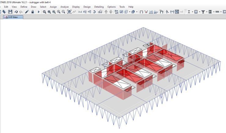
As discussed in section 2, a generic commercial building having 54 storey and floor area of 49.7x49.7m has been assumed.TheETABSmodelforthebuildingalongwiththe outriggercombinationsisshowninfigures3to5
Fig 5 3DViewofShearCoreandTwoOutriggerswith BeltTrussModel
The above analysis for the various structural model combinationlistedinsection2.2wereperformedonbasis of the two performance evaluations parameters namely Topstoreydisplacementandstoreydriftratios.
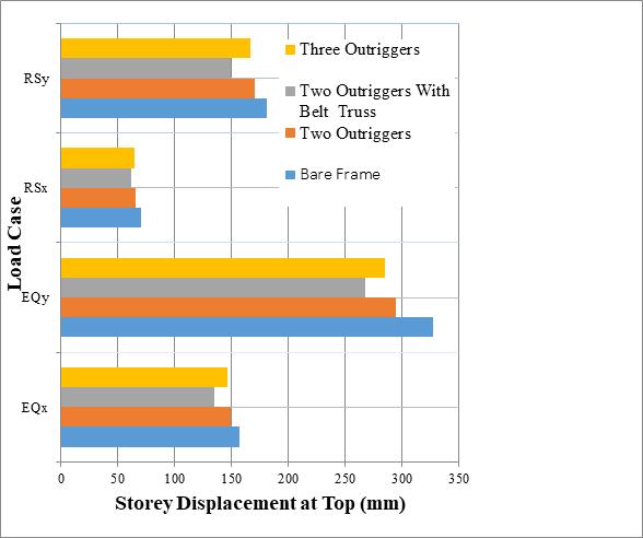
The top storey displacement represents the maximum deflection that a tall building experiences. In this study this displacement is compared for various structural modelsalongthexandydirectionsasshowninChart1.
Fig - 3 FloorViewofShearCoreandTwoOutriggerswith BeltTrussModel
Fig 4 ElevationofShearCoreandTwoOutriggerswith BeltTrussModel
Chart 1 TopStoryDisplacementusingResponse Spectrummethod(RS)andEquivalentstaticmethod(EQ)
Itisseenthattheequivalentstaticmethodshowsgreater displacementascomparedtotheresponsespectrumalong both the direction. Furthermore, it is seen that deflection along the y direction is greater than x direction despite
Volume: 09 Issue: 07 | July 2022 www.irjet.net p ISSN: 2395 0072 © 2021, IRJET | Impact Factor value: 7.529 | ISO 9001:2008 Certified Journal | Page1080
International Research Journal of Engineering and Technology (IRJET) e ISSN: 2395 0056
Volume: 09 Issue: 07 | July 2022 www.irjet.net p ISSN: 2395 0072
being symmetrical building this difference in the directional displacement because the outriggers in X direction are aligned on either side of the Shear wall core whereas; it is slightly staggered in Y direction. Additionally,itisseenthatthemaximumtopdisplacement reduction of 18% compared to the bare frame occurs in thecaseoftwooutriggerswithperipheralbelttruss.
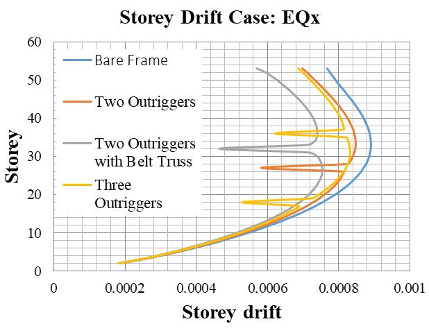
Storey drift is the difference between the lateral displacement of a floor to the floor below and the storey drift ratio is the storey drift divided by the storey height. Chart 2 show the storey drift ratios for various structural combination using the equivalent static method along the x and y directions. Similarly, Chart 3 shows storey drift ratiosusingtheresponsespectrummethod.
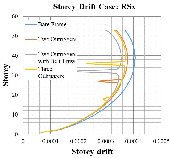
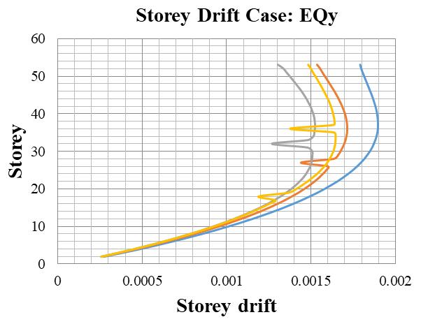
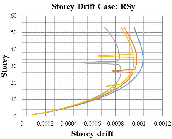
Chart 2 StoreydriftvariationusingEquivalentStatic method(EQ)alongXandYdirections
Chart 3 StoreydriftvariationusingResponseSpectrum method(RS)alongXandYdirections
The work in this research has analyzed the effect of outriggers in various configurations on the displacement and drift of tall buildings in particular the linear analysis wasdoneusingtheequivalentstaticmethodandresponse spectrum method in ETABS software. It is seen that outriggers significantly reduce the maximum displacement and storey drift in the structure. In particular, the two outrigger with belt truss combination performedthebestofferingmaximumof18%reductionin top storey displacement and 27% reduction of top storey driftcomparedtobareframemodel
Rafid Kunglay wishes his sincere thanks to all those who had directly or indirectly contributed in successfully completion of this paper publication and expressing his gratitude to Dr. N.G.Gore, professor of civil engineering department, MGMCET, Kamothe, M.H., India, for his inspiring and valuable advice and guidance in publishing thispaper
International Research Journal of Engineering and Technology (IRJET) e ISSN: 2395 0056
[1] Akash Kala, MadhuriMangulkar, Indrajeet Jain, “Optimum Position of Outrigger with belt truss in tall building under horizontal load” International Conference on Advances in Civil Engineering, February2016.
[2] AkshayKhanorkar, ShrutiSukhdeve, S.V. Denge, S.P. Raut, “Outrigger and Belt Truss System for Tall Building to Control Deflection: A Review” GRD Journals Global Research and Development Journal forEngineering,May2016.
[3] M.R. Suresh, Pradeep K.M., “Influence Of Outrigger System in RC Structures for Different Seismic Zones”, IJSRD International Journal forScientificResearch& Development,May2015.
[4] MohdAbdusSattar, SanjeevRao, Madan Mohan, DR. Sreenatha Reddy,“Deflection Control in High Rise Building Using Belt Truss and Outrigger Systems”, InternationalJournalofAppliedSciences,Engineering andManagement,November2014.
[5] KiranKamath,AvinashA.R.,SandeshUpadhyayaK.,“A Studyontheperformanceofmulti outriggerstructure subjected to Seismic loads”, IOSR Journal of MechanicalandCivilEngineering,2014.
[6] Dr.K.S.Sathyanarayanan,A.VijayandS.Balachandar, “FeasibilityStudiesontheUseofOutriggerSystemfor RCCoreFrames”IJAITI,May2012.
[7] IS 1893 (Part 1) 2002,"criteria for earthquake resistantdesignofstructures"
[8] IS 875 (Part 3) 1987,"criteria for wind resistant designofstructures"
[9] IS456 2000,"PlainandReinforcedconcrete"
Volume: 09 Issue: 07 | July 2022 www.irjet.net p ISSN: 2395 0072 © 2021, IRJET | Impact Factor value: 7.529 | ISO 9001:2008 Certified Journal | Page1082