International Research Journal of Engineering and Technology (IRJET) e-ISSN: 2395-0056

Volume: 09 Issue: 07 | July 2022 www.irjet.net p-ISSN: 2395-0072
International Research Journal of Engineering and Technology (IRJET) e-ISSN: 2395-0056
Volume: 09 Issue: 07 | July 2022 www.irjet.net p-ISSN: 2395-0072
Dheeraj Kumar Singh1 , Maaz Sultan2 , Baharuddin Laskar3 , Ziauddin Ahmed Khan4
1Bridge Design Engineer, Specialized Engineering Services Pvt. Ltd., Noida, India
2Bridge Design Engineer, Specialized Engineering Services Pvt. Ltd., Noida, India
3 Design Consultant, Specialized Engineering Services Pvt. Ltd., Noida, India
4Managing Director, Specialized Engineering Services Pvt. Ltd., Noida, India ***
Abstract This article proposes a method to use voided slab over bridge deck. In present study a void slab is casted over deck slab to match the F.R.L of the highway. The RCC fill over a bridge deck is not feasible due to heavy dead weight of concrete. This practice is may be adopted for retrofitting and retaining existing bridge in lieu of demolishing and re construction new bridge to accommodate new highway construction. In solid slabs, voids are added to the concrete section to lower the self weight of the material without reducing its flexural strength. This technique offers many advantages over a conventional solid concrete slab like less material consumption, cheaper construction costs, and improved structural efficiency are all benefits of solid concrete slabs. This paper also introduces essential techniques for reducing the dead weight of the concrete by using voids above deck slab with help polystyrene boxes and its design to resist heavy traffic moment Although, presence of voids within the concrete structure makes analysis of structure very complicated but still we have developed a rational and comprehension approach as per codal provisions
Key Words: Voided slab, Retrofitting, Deck slab, Bridge and Staad Pro.
Abridgeisabuildingthatcrossesoverthesupportsanddistributestheweighttothe supportsusingaslabdeck,girders, andfoundationpiers.Slabdeckisthekeycomponentfortransmittingtheweightofavehicleandpersonstothesupports. Thedeckslabmaybesolidorcontainlongitudinalandcrossgirderstodistributetheweighttothepedestals.Forthesame span, solid slab type bridges require more steel and concrete than girder bridges do. A solid portion, free of beams or cavities, makes up solid slab decks. Bridge building frequently use this style of deck. The cross section of the slabs is a homogenous constructionsincetheyaresolidatall points. Concreteplacementis madesimplerasa resultof thelack of reinforcing congestion. Solidslabs oneandonlysignificantdrawback isthesubstantial amountof concretetheyrequire. This has an impact on the bridge structure's cost and self weight. These slabs have increased self weight because of the high concrete volume. The span of the slab between columns/Piers is a major design restriction when creating a reinforcedconcretestructure.Largespansbetweencolumnssometimescallforparticularlythickslabsand/orsupporting beams,whichaddstothestructure'sweightbyrequiringtheuseofalotofconcrete.
The present bridge is approximate 10 year old, width of bridge is 13 m and span 20 m. The deck slab is casted over 4 girdersofdepth2m eachandspacingof3meters. AsperIRC6 2017the current bridge wasdesignedfor3lanetraffic moment with vehicle combination either deck width should be designed for 3 lane traffic maximum bending moment generated from either 3 lanes of class A loading , one lane class A+ one lane class 70R loading and one lane of special vehicle loading. Here in this case Special Vehicle loading produces the maximum bending moment which is acting as governing live load. Similarly wearing course load, Crash Barrier loading, deck slabweight and Self weight are acting on girders. The loadcombinationsfor SLS(Serviceability Limit State) andULS(UltimatelimitState)loading stateare asper IRC6:2017.
The corresponding highway is upgraded, hence FRL is increased up to 801 mm on A1 side of bridge and 430 mm on A2 sideofbridge.Seeingthecurrentconditionofbridgeiswasdecidedtoretainthebridgeandmatchthenewroad FRLby placingthefillondeckslab.LayingofRCCoverdeckslabtomatchtheFRLwasnotsafeastheULSmomentexceededthe Capacityofthebridgegirders.Hereweareusingpolystyrenefoamboxesasameantocastvoidsslab.Thedensityofboxis 25kg/m3 anddirectlyobtainedfromlocalmanufacturer.
International Research Journal of Engineering and Technology (IRJET) e ISSN: 2395 0056
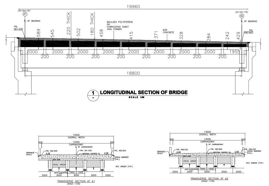
Figure.1
Figure.2
Volume: 09 Issue: 07 | July 2022 www.irjet.net p ISSN: 2395 0072 © 2022, IRJET | Impact Factor value: 7.529 | ISO 9001:2008 Certified Journal | Page1066
International Research Journal of Engineering and Technology (IRJET) e ISSN: 2395 0056
Volume: 09 Issue: 07 | July 2022 www.irjet.net p ISSN: 2395 0072
Thevoidslabapproachisadatedone.Foraverylongtime,engineersanddevelopersofformingequipmenthavereduced the weight of floor slabs by producing voids using a number of methods. However, more recent techniques now make it feasibletolowertotalcostsandboosttheeffectivenessofcast in situconcretestructures.Byreducingthestructure'sself weight,voidedslabsaimtomaximizethe benefitsofconcreteslabconstructionwhileeliminatingthedrawbacksofsolid slabs.Thissectionexaminesmanyprevioususesofvoidedslabsaswellastheideaofvoidedslabstructure.Voidedslabs are not a novel approach to construction. Voided slabs in various forms have been used for ages. Although the ideas of voidedslabswereemployedforages,therearenumerousstructuresdevelopedsince20thcentury.
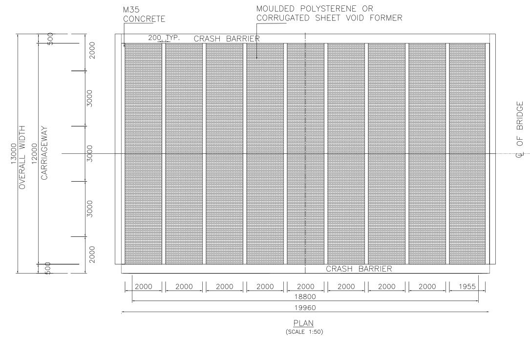
Voidedslabsare characterized by the presenceofvoids withintheslab. Thevoidshereare formed byusing rectangular Polystyrene foam box placed along width of deck slab. Grade of concrete is M 35 .The minimum longitudinal reinforcement asper clause305.19 ofIRC:21 2000.The minimumtransverse reinforcement 1%of area ofslab. Voidsin the slab help reduce the self weight of the structure. Thus, the major function of voided slabs is to reduce the concrete volumeandtherebydecreasetheself weightoftheslab.Ifdesignedproperly,itcanreducetheself weightoftheslabup to60%ascomparedtoasolidslabforthesamesectionandspan(Figure 1).AsperIRC SP64 2005,thevoidedslabscan bemodeledanddesignedbythemethodsameasthatusedforsolidslabs,theaveragefilloverboxesisof200mmandthe fillisRCCdeckslabof220mmdepth.TheheightofpolystyreneboxdecreasesformA1sidetoA2tomatchtheFinishRoad Level (FRL).
Thetwomaintechniquesforbuildingvoidslabsystemsarethefiligreeapproach,inwhichsomecomponentsareprecast at a workshop or concrete yard, and the on site method, in which the entire system is cast. Both methods use the basic three components. In both methods, Polystyrene box void is main component. These voids are often Tubular, spherical, hollow and rectangular which is made of polystyrene. The presence of voids makes the slab lighter than conventional concrete slabs. The steel cage is an additional component. The slab is reinforced with steel to prevent flexure, and the voids are held in place in the middle of the slab by a cage made of thin steel. Concrete, the third element, surrounds the voids and ultimately decides the strength of the slab Concrete, the third element, surrounds the voids and ultimately decidesthestrengthoftheslab.Thelastcomponentistheverticalreinforcementofwebwhichisdrilled&insertedusing HILTIEquipmentandepoxyinthedeckslab.Theinitialdepthofverticalbaris300mmnearA1sideofbridgeandthe150 mmsubsequentlyasshownin Figure 1
The staad modelling was done using grillage analogy similar to the analogy employed in design of girders. The original Staadfileisshownin Figure 3
Inthefirststep;agrillageof1.5x2.2mwascreated.ForUppersolidportionofVoidSlabaconcretemember(rectangular) of uniform thickness 200mm was defined. Figure 4.This property was assigned to the upper slab and vertical members thatconnecttheslabtothedeckslabcumgirderarrangementthuscreatingavoidslabgrillage abovetheoriginalbridge grillagefile
In second step; Loading was defined and imposed on the structure. Dead load comprised of loads due to Surfacing, Self weight of slab, SIDL (Crash Barrier). Then for live load, vehicles as per IRC: 6 were defined in Vehicle Definitions and Combinations of the same were generated. Impact factor 1.15 as per IRC: 6:2017.The ULS Bending moment and Shear ForcesummaryforgirderwithVoidedSlabareshownin Table.1 andtheULSdesignchecksareshownin Table. 2. The ULS Bending moment and Shear Force summary for original bridge girder are shown in Table.3 and the ULS design checksareshownin Table. 4.
Alltheloadswereassignedtothegrillageandthestructurewas analyzed.Theresultswereobtainedafteranalysiswere themax/minvaluesofmomentsandshearobtainedfromthetable bendingmomenttableinstaadweredividedby2.2m to obtain the per meter values to be considered for further design of slab and reinforcement detailing. The detail calculationofwebisshowinAnnexure IandforflangeinAnnexure II.The Figure 5 showsthereinforcementdetailingof voidedslabaftercalculation.
International Research Journal of Engineering and Technology (IRJET) e ISSN: 2395 0056
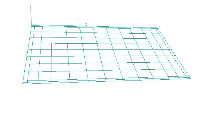
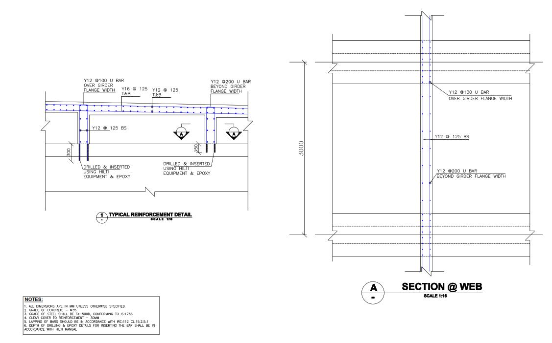
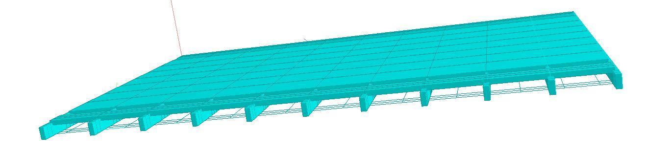
Figure 3
Figure 4
Figure 5
Volume: 09 Issue: 07 | July 2022 www.irjet.net p ISSN: 2395 0072 © 2022, IRJET | Impact Factor value: 7.529 | ISO 9001:2008 Certified Journal |
International Research Journal of Engineering and Technology (IRJET) e ISSN: 2395 0056
Volume: 09 Issue: 07 | July 2022 www.irjet.net p ISSN: 2395 0072
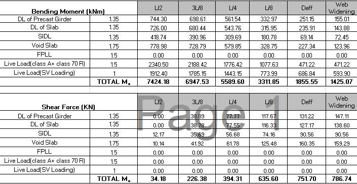
Table 1 ULSBendingmomentandShearForceforvoidedslaboverofbridge
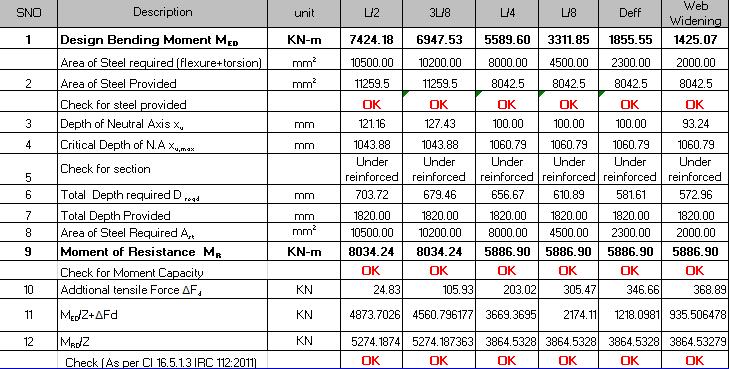
Table 2 ULSDesigncheckforviodedslaboverbridge
International Research Journal of Engineering and Technology (IRJET) e ISSN: 2395 0056
Volume: 09 Issue: 07 | July 2022 www.irjet.net p ISSN: 2395 0072
L/2 3L/8 L/4 L/8 Deff Web Widening
DLof PrecastGirder 1.35 744.30 698.61 561.54 332.97 251.15 155.01
DLof Slab 1.35 726.00 680.44 543.76 315.95 235.91 143.88
SIDL 1.35 418.74 390.96 309.69 180.78 69.14 72.45 Surfacing 1.75 308.03 289.78 234.92 61.35 61.35 58.40 FPLL 1.5 0.00 0.00 0.00 0.00 0.00 0.00
LiveLoad(classA+class70R) 1.5 2340.50 2188.42 1776.42 1077.63 471.22 471.22
LiveLoad(SVLoading) 1 1912.40 1785.15 1443.15 773.99 686.84 593.90
TOTALMu 6600.01 6179.25 4985.97 2843.90 1565.07 1310.33
L/2 3L/8 L/4 L/8 Deff Web Widening
DLof PrecastGirder 1.35 0.00 38.89 77.77 117.67 131.22 147.11 DLof Slab 1.35 0.00 38.78 77.55 116.33 127.17 138.60 SIDL 1.35 12.17 35.69 56.68 74.16 90.56 90.56 Surfacing 1.75 10.89 27.03 43.47 55.56 62.18 52.14
FPLL 1.5 0.00 0.00 0.00 0.00 0.00 0.00
LiveLoad(classA+class70R) 1.5 0.00 0.00 0.00 0.00 0.00 0.00 LiveLoad(SVLoading) 1 0.00 0.00 0.00 0.00 0.00 0.00 TOTALMu 35.49 200.33 362.28 513.25 579.91 599.22
BendingMoment (kNm) Shear Force(KN) SNO
Table3 ULSBendingmomentforexistingbridge
Description DesignBendingMomentMED AreaofSteelrequired(flexure+torsion)
AreaofSteelProvided DepthofNuetralAxisxu CriticalDepthofN.Axu,max Checkforsection Total DepthrequiredD reqd TotalDepthProvided
AreaofSteelRequiredAst MomentofResistance MR CheckforMomentCapacity Addtional tensile Force ΔFd MED/Z+ΔFd MRD/Z
L/2 3L/8
Deff Web Widening 1 KN-m 6600.01 6179.25 4985.97 2843.90 1565.07 1310.33 mm 2 10500.00 10200.00 8000.00 4500.00 2300.00 2000.00 2 mm 2 11259.5 11259.5 8042.5 8042.5 8042.5 8042.5 Checkforsteelprovided OK OK OK OK OK OK 3 mm 121.16 127.43 100.00 100.00 100.00 93.24 4 mm 1043.88 1043.88 1060.79 1060.79 1060.79 1060.79 5 Under reinforced Under reinforced Under reinforced Under reinforce Under reinforced Under reinforced 6 mm 670.36 663.77 644.54 601.48 575.78 570.65 7 mm 1820.00 1820.00 1820.00 1820.00 1820.00 1820.00 8 mm 2 10500.00 10200.00 8000.00 4500.00 2300.00 2000.00 9 KN-m 8034.24 8034.24 5886.90 5886.90 5886.90 5886.90 OK OK OK OK OK OK 10 KN 24.83 105.93 203.02 305.47 346.66 368.89 11 KN 4332.668 4056.4544 3273.107 1866.92 1027.414 860.1858 12 KN 5274.187 5274.1874 3864.533 3864.53 3864.533 3864.533 OK OK OK OK OK OK Check(Asper16.5.1.3IRC112.2011)
Table 4 DesigncheckforULSexistingbridge 4.0
Costreductionforthesubstructure,suchasfootingsandpiers,ispossiblewithadecreaseindeadweightofupto 35%. The structural engineer may lighten the slabby utilizing the concrete more effectively. Reduction inconcreteisveryenvironmentallyfriendlyandsustainable lowerenergyandcarbonemissions.
International Research Journal of Engineering and Technology (IRJET) e ISSN: 2395 0056
Volume: 09 Issue: 07 | July 2022 www.irjet.net p ISSN: 2395 0072
Longercolumnspacingismadepossiblewithoutsignificantlythickeningtheslab.Toprovideathinslababroader span,voidedslabscanbenefitfrompost tensionedreinforcement.
Constructiontimescanbeshortenedbysomevoided slabsystems,notablythosethatareprecastormountedon flat plateformingprocesses.
Although concretecannotbeeliminatedfrom all areasina floorslab,voidsare excluded nearcolumnstoretain slab punching shear capability. This decreased weight of building floors also enables engineers to reduce columns,walls,andfoundationsbyupto40%.
Inthepresentpaper,weproposedtheadvantagesofvoideddeckslab.Acomprehensivestudyisdonetounderstandthe behavior of deck slab with increase in FRL. A comparison of Solid Deck Fill versus Void deck slab is done for our bridge anditfoundthatanapproximatevolumeof58.368m3 issavedusingvoidedslabconstructionhencelessself weightand eventually passing all the design checks for girder, bearings and foundation. The ULS moment (Demand) is found to be less than MOR Moment of Resistance (Moment Capacity) (Table 3 & 4), hence we are able to retain our existing bridge and save the cost for new bridge. The quantity of RCC fill to match FRL was calculated to be approximately 147.6 m3 , whereaswhenthisvoidedslabtechniqueisusedthefillvoidisaround58.368m3.Resultsshowthatconcretevolumecan bereducedsignificantlyby60.4%,
[1] IRC:5 2015,'GeneralSpecificationsforRoadBridges'.
[2] IRC:6 2017,'RoadBridges,Sec IILoads&Stresses'.
[3] IRC:78 2014,'RoadBridges,Sec VII,Foundations&Substructures'.
[4] IRC:112 2011,'NewRCCDesign'.
[5] IRCSP105 2015,'ExplanatoryHandbooktoIRC112 2011'.
[6] IS:456 2000,'Plain&ReinforcedConcrete'.
[7] IS:1893_3 2014,'Bridges&RetainingWalls'.
[8] IRCSP64 2005Guidelinesfortheanalysisanddesignofcast in placevoidedslabsuperstructure
Annexure 1
Designofwebofvoidedslab:
UnitweightofRCC concrete= 25 kN/m3
UnitweightofPQC= 24 kN/m3
Heightofsection,h= 0.800 m
Depthoffooting,Df = 1.000 m
ForGradeofconcreteM(), fck = 35 MPa
SecantModulusof ElasticityofConcrete,Ecm= 32000 MPa (IRC 112Table6.5)
ForGradeFe500Dsteel,fyk = 500 MPa
ClearCoverto reinforcement= 30 mm
MeanAxialTensile
StrengthofConcrete,fctm= 2.80 MPa (IRC 112Table6.5) AllowableBondStress,tbd = 1.8 MPa (IS 456Cl.26.2.1.1) b1 = 0.8 (SP105Table8.2)
2022, IRJET | Impact Factor value: 7.529 | ISO 9001:2008 Certified Journal |
International Research Journal of Engineering and Technology (IRJET) e ISSN: 2395 0056
b2 = 0.4
DesignCompressive Strengthofconcrete,fcd= α*fck/gm where,α= 0.67 (IRC 112Cl.6.4.2.8) gm= 1.50 Basic/Seismic = 1.20 Accidental fcd= 15.63 MPa Basic/Seismic = 19.54 MPa Accidental
DepthofSection= 200 mm Effectivedepth,d= 164 mm
Effectivewidth,bw = 1000 mm
BrakingForce=255.4kN
Deck width= 13m
Brakingload =19.65 kN/m (IRC:6 2017Cl.211.2)
Heightofsection,h= 0.80 m BendingMomentdueto brakingforce,Mbraking = 15.72 kN m/m (Brakingloadxh)
Momentduetoliveload, MLL = 21.68 kN m/m (STAAD)
DesignMoment,MED = 37.40 kN m/m
NeutralAxisdepth,x= [(d/2b2) {(d/2b2)2 (MED/b1b2bfcd)}0.5] = 19.1 mm
Leverarm,z= d b2x = 156.4 mm
AreaofSteelrequired, Astreqd= MED/(0.87fyz) = 5.5 cm²/m
Astmin= (0.26xfctm xbx d)/fyk
AsperClause 16.5.1.1 = 2.4 cm²/m IRC:112 2020
Astmin= 0.0013xbxd = 2.1 cm²/m
ProvideRebarDia.f= 12 mm Spacing= 200 mm
Asprov.= 5.7 cm²/m Satisfactory
Impact Factor value: 7.529 | ISO 9001:2008 Certified Journal | Page1072
Volume: 09 Issue: 07 | July 2022 www.irjet.net p ISSN: 2395 0072 © 2022, IRJET |
International Research Journal of Engineering and Technology (IRJET) e ISSN: 2395 0056
Volume: 09 Issue: 07 | July 2022 www.irjet.net p ISSN: 2395 0072
Annexure-II
DesignofSlabportionofvoidedslab MaterialSpecification
CharacteristicCompressive
DesignCompressivestrengthof Concrete,fcd
Tensilestrengthofconcrete, fctm
StrainatreachingCharacteistic Strength, ec2
UltimateStrain, ecu2 Ecm
Concrete Grade = M 35 = 35.00 Mpaat28days -ReferTableNo6.5ofIRC:112-2011 = 15.63 Mpaat28days(0.67/1.5*fck) -ReferFig6.5ofIRC:112-2011 = 2.77 MPa = 0.02 -ReferTableNo6.5ofIRC:112-2011 = 0.035 -ReferTableNo6.5ofIRC:112-2011 = 3.23E+04 N/mm2
-ReferTable6.5ofIRC:112-2011and Annexure-A-2.2
-ReferTableNo6.5ofIRC:112-2011 andAnnexureA-2.2
YieldStrengthofReinforcement, fyorfyk
SteelGrade = Fe 500 D(HYSDSteel) = 500 Mpa
DesignYieldStrengthof Reinforcement,fyd
ModulusofElasticityofSteel( Es)
-ReferTableNo18.1ofIRC:112-2011 = 434.78 Mpa (1/1.15*fy) -ReferFig6.4ofIRC:112-2011 = 2.00E+05 Mpa -ReferClause6.3.5ofIRC:112-2011
DryweightofConcrete = 25 kN/m3 -ReferClause203ofIRC:6-2017 Dryunit weightofsoil = 20 kN/m3 -ReferClause203ofIRC:6-2017
Maximumcompressivestressin concreteunderrarecombination
Maximumtensilestressinsteel underrarecombination
PermissibleCrackWidth = 0.3 mm-ForSevereExposureCondition-ReferTable12.1ofIRC:112-2011 = 0.48fck -ReferClause12.2.1ofIRC:112-2011 = 16.8 N/mm2 = 300 N/mm2 -ReferClause12.2.2ofIRC:112-2011
International Research Journal of Engineering and Technology (IRJET) e ISSN: 2395 0056
Volume: 09 Issue: 07 | July 2022 www.irjet.net p ISSN: 2395 0072
SupportReinforcementCalculation:
Thicknessof slab = 180 mm atInteriorspan
Thicknessof slab = 180 mm (atcantilever)
ClearCovertooutersteeel = 30 mm
MaximumDiameterofReinforcement = 16 mm
EffectiveDepthProvided(deff) = 142 mm
Designbendingmoment (HOGGING) = 21.68 kNm/m (FROMSTAADRESULTS)withIF=1.15
Mulim = 0.165xfckx bxd^2 = 21.68 kNm/m (EquationderivedbasedonIRC:112-2011) = SQRT( 21.68 x 1000000 0.165x 35.00 x1000
EffectiveDepthofCap Required(dreq) )
EffectiveDepthofCapRequired(dreq) = 61.271 mm
TotalDepthRequired(Dreq) = 99.27 mm
TotalDepthProvided(Dprov) = 180.00 mm OK
R=MRD/(bd^2) = 1.08
DesignMomentofResistance MRD = 0.87fyAst*(d-(lxu/2)) 21.68 = 0.87fyAst*(d-(lxu/2)) h = 1 fcd = 15.61 N/mm2 fy = 500 N/mm2 l = 0.8 MRD = 0.87fyAst*(d-(0.87*fy*Ast/(b*n*fcd*2))
AreaofSteelRequired,Astred = 363.98 mm2/m = 363.98 mm2/m Astreq = 363.98 mm2/m
MinimumLongitudinalReinforcement: As.Min = 0.26x fctm x b.d -ReferEq.16.5.1.1&16.6.1.1ofIRC:112-2011 fyk
Whicheverishigher OR = 0.0015 x b.d-ReferClause16.9ofIRC:112-2011' b = 1000.00 mm d = 142.00 mm Astmin = 213.00 mm2/m GoverningReinf.Ast = 363.98 mm2/m Provide 16 mmdia@ 125 mmc/c + 0 mmdia@ 250 mmc/c
Areaprovided= 1608.50 mm2/m > 363.98 mm2/m OK PercentageofSteel(pt%) = 1.13 % MaximumSpacingofBars: asperClause16.6.1.1ofIRC:112-2011 Smax = 2h = 284.00 OR = 250.00 mm whicheverismax ProvidedSpacingislessthanSmax,HenceOK MomentofResistanceofSectioncorrespondingtoProvidedAst MRD = 0.87fyAst*(d-(0.87*fy*Ast/(b*n*fcd*2)) = 83.68 kNm > 21.68 kNm SAFE
Distributionreinforcement: EffectiveDepthinLong.Direction = 128 mm AsperClause16.6.1.1.ofIRC:112-2011,SecondaryReinforcementshallbeatleast20%ofthemainreinforcement 20.00 x 1608.50 = 321.699 mm2/m 100.00 Provide 12 mmdia@ 125 mmc/catTransdirectionintopface.(Providing= 904.779 mm^2)
International Research Journal of Engineering and Technology (IRJET) e ISSN: 2395 0056
Volume: 09 Issue: 07 | July 2022 www.irjet.net p ISSN: 2395 0072
SpanReinforcementCalculation: (SAGGINGATMIDSPAN)
ClearCovertooutersteeel = 30 mm
MaximumDiameterofReinformcement = 16 mm
EffectiveDepthProvided(deff) = 142 mm Designbendingmoment(SAGGING) = 7.32 kNm/m (FROMSTAADRESULTS)withIF=1.15 Mult = 0.165xfckx bxd^2 = 7.32 kNm/m = SQRT( 7.32 x 1000000 0.165x 35.00 x1000
EffectiveDepthofCap Required(dreq) )
EffectiveDepthofCapRequired(dreq) = 35.590 mm
TotalDepthRequired(Dreq) = 73.59 mm TotalDepthProvided(Dprov) = 180.00 mm OK R=Mu/(bd^2) = 0.36
AstRequired:
MRD = 0.87fyAst*(d-(0.87*fy*Ast/(b*n*fcd*2))
AreaofSteelRequired,Astred = 119.834 mm2/m = 119.83 mm2/m Astreq = 119.83 mm2/m
MinimumLongitudinalReinforcement: As.Min = 0.26x fctm x b.d -ReferEq.16.5.1.1&16.6.1.1ofIRC:112-2011 fyk
Whicheverishigher OR = 0.0015 x b.d-ReferClause16.9ofIRC:112-2011' b = 1000.00 mm d = 142.00 mm
Astmin = 213.00 mm2/m
GoverningReinf.Ast = 213.00 mm2/m
Provide 16 mmdia@ 125 mmc/c + 0 mmdia@ 100 mmc/c
Areaprovided= 1608.50 mm2/m > 213.00 mm2/m OK PercentageofSteel(pt%) = 1.13 %
MaximumSpacingofBars: asperClause16.6.1.1ofIRC:112-2011 Smax = 2h = 284.00 OR = 250.00 mm whicheverismax
ProvidedSpacingislessthanSmax,HenceOK
MomentofResistanceofSectioncorrespondingtoProvidedAst MRD = 0.87fyAst*(d-(0.87*fy*Ast/(b*n*fcd*2)) = 83.68 kNm > 7.32 kNm SAFE
Distributionreinforcement:
EffectiveDepthinLong.Direction = 132 mm
AsperClause16.6.1.1.ofIRC:112-2011,SecondaryReinforcementshallbeatleast20%ofthemainreinforcement 20.00 x 1608.50 = 321.699 mm2/m 100.00
Provide 12 mmdia@ 125 mmc/catTransdirectionintopface.(Providing= 904.7786842 mm^2)
International Research Journal of Engineering and Technology (IRJET) e ISSN: 2395 0056
Volume: 09 Issue: 07 | July 2022 www.irjet.net p ISSN: 2395 0072
CheckForShear
SF= 58.4 kN fromSTAADresults
DesignShearStrengthofConcrete,(tc)withoutShearReinforcement:
AsperClause10.3.2ofIRC:112-2011, Designshearresistanceofthememberwithoutshearreinforcementisgivenby: eq.1
Subjectedtominimumof eq.2 where, K= 1+SQRT(200/d) ≤2.0 ,wheredis depthinmm K= 2.00 vmin= 0.031K3/2 fck1/2 ,fck= 35.00 N/mm2 Hence vmin= 0.519 N/mm2 scp = Concretecompressivestressinconcreteatcentroidalaxisinthedirectionofaxialloadorprestressing scp = NEd/Ac <0.2fcd where,fcd= 0.67fck/1.5 scp = 0.00 N/mm2 Hence, tc = VRd,c/(bw.d) = Vmin +0.15 scp = 0.5187 N/mm2 Fromeq.1
r1 = SteelRatio=Asl/(bw.d) ≤ 0.02 Hence r1 = 0.0113
tc = VRd,c/(bw.d) = 0.760 N/mm2 Fromeq.2
Maxofeq.1&eq.2 tc = VRd,c/(bw.d) = 0.760 N/mm2
Correspondstosteelratio=1.133%&M35Gradeof Concrete
Shearstress(vEd) = Ved/(bw*z) ,where z=0.9deff
vEd = 58400.000 = 0.457 N/mm2 < 1000.00 x 127.80
AsTvislesserthanTcHenceNoShearReinforcementisneedtobeprovided.
0.760MPa