Volume: 09 Issue: 07 | July 2022 www.irjet.net p-ISSN: 2395-0072

Volume: 09 Issue: 07 | July 2022 www.irjet.net p-ISSN: 2395-0072
1P SHAMEEM 2L SURESH
PG STUDENT (184M1D5405), DEPT.OF EEE,VEMU INSTITUTE OF TECHNOLOGY,P.KOTHAKOTA 517112 ASSISTANT PROFESSOR, DEPT.OF EEE, VEMU INSTITUTE OF TECHNOLOGY, P.KOTHAKOTA 517112 ***
Abstract In this paper, an implementation of solar photovoltaic (PV) array powered grid connected, residential electric vehicle (EV) charger is presented, which caters the need of an EV, household loads and the grid. The charger is enabled to operate autonomously using a PV array for providing an uninterruptible charging and power to householdloads. However, in the absence of the PV array or insufficient PV array generation, the grid connected mode of operation is presented. Moreover, the charger is supported with the synchronization and seamless mode switching control, so that the charger automatically connects/disconnects from the grid without disturbing the EV charging and household supply. The charger is also enabled with the vehicle to grid (V2G) active/reactive power support to the grid and vehicle to home (V2H) power transfer for supporting the local loads in an islanded condition. The charger is also controlled to operate as an active power filter for achieving the unity power factor (UPF) operation and total harmonic distortion (THD) of the grid current within 5%. Moreover, for achieving energy management, a dc link voltage regulation based energy management strategy is used and a sliding mode control (SMC) is used for regulating the dc link voltage. For satisfactory operation under distorted voltage condition, a second-order generalized integrator frequency locked loop with dc offset rejection (SOGI FLL DR), isused togenerate the sinusoidal reference grid current. The charger is designed for a single phase 230V, 50Hz grid and it is experimentally validated in the laboratory.
Keywords— Electric vehicle, bi-directional charger, solar PV generation, reactive power, power quality.
In the current scenario, the electric vehicle (EV) is emerging as a promising solution to the problems caused by fossil fuel powered vehicles [1]. However, the adaptability of EV depends on the charging infrastructure [2].ThechargingofEVrequiresahugeamountofelectrical energy, which mostly comes from coal/ gas based power plants.Therefore,inatruesense,theEVscanbeagreenand cleanalternativetothepresenttransportsystemwhenthe electrical energy required for the charging of EV, comes fromtherenewableenergysourcessuchassolar,windetc. [3]. The advantage of this kind of charging station is that thePVarraypowerisgeneratedandusedlocally.Because
ofthis,thetransmissionlines need notbeupgraded forthe highpower.Moreover,thechargingstationdoesnotrequire todrawpowerfromthegridwhenthecostofenergyishigh. Another advantage of PV array based charging station is that it is not location specific. Ma et al. [4] have proposed the use of office building and parking area for laying down thesolarPVpanels,asthesesolarPVpanelsalsoworkasa shed and prevent the heating of the vehicles and buildings. Therefore, the use of PV array based charging station not onlyavoidsoverloadingofthegrid,butitalsominimizesthe operational cost of the charging station. Moreover, the coordinatedoperationofthePV arrayandEVmitigatesthe impactsofPVgenerationontheutility,anditeliminatesthe problems caused by the solar PV generation intermittency [5].
Therefore, many researchers have contributed their work for developing the PV array based charging station. Gunter et al. [6]andSatpathyetal.[7] haveproposedthePVarrayand wind energy basedgridconnectedsystem.Marraetal.[8], Saxenaetal. [9], Monteiro et al. [10], Tran et al. [11], and Tazay et al. [12] have reported the implementation of the PV array basedEVchargingstation.However,intheliterature,adc dc converter (mostly boost converter) is used to connect thePVarraytothedclink.Inthispaper,thesolarPVarray isdirectlyconnectedtothedclink.Themajoradvantagesof this topology, include the reduction in one power stage through the elimination of dc dc converter stage, circuit complexity and the cost of the converter, without compromisingtheperformanceof the PV array. Moreover, this topology is a kind of retrofit solution wherein the PV array can be augmented to the existing charging infrastructure with minimum change in the software (maximumpowerpointtrackingcontrolalgorithm)alone.
However,ifthecharger isusedonlyforcharging the EV, the charger remains idle for at least 50% of the lifetime. Therefore, the converter of the charger has to be used for other tasks to improve the operational efficiency of the charger when the EV is not connected for charging. There are manyfunctionalities proposedintheliteraturesuchas the four quadrant operation of charger, vehicle to home operationusingtheEVbatteryandactivefilteringetc.[13]. However, in the available literature, different converters and controls are used for different modes of operation. Moreover, the charger operation is restricted by the grid availability(islandedorgridconnectedoperation),typesof mode switching among different operating modes (seamlessordiscontinuous)andtheseconditionsaffectthe
Volume: 09 Issue: 07 | July 2022
www.irjet.net p-ISSN: 2395-0072
operational efficiency of the charger. Many efforts are being made to develop an integrated system with the capability to performthe above functionalities, which are beneficial to the grid, household loads and the EVs [14]. Kikusato et al. [15] have proposed a framework for the charge/discharge management of EV battery using the forecasted information of home and grid management system so that the PV array power is utilized maximally andverylesspowerisdrawnfromthegrid.Sunetal.[16] haveproposedthestrategyforminimizingtheresidential energy cost considering the driving pattern and the vehicle to grid (V2G) power transfer in EV integrated PV arrayandbattery basedresidentialmicrogrid.Bhamidiet al. [17] have proposed the optimal planning and operational strategyofresidentialmicrogridparticipating in demand side management. Yang et al. [18] have reported a strategy for distributed coordination of EV charging with renewable energy in the microgrid of building. Chaudhari et al. [19] have proposed a have developed a chance constrained based control strategy for microgrid and the integrated EV. Turker et al. [21] have minimized the charging cost of the EV using vehicle togridandvehicletohomefunctionality.Erdincetal.[22] have proposed a smart household operation with bidirectional EV and energy storage. However, from the review, it is observed that the recent literature is dominatedbythe controlandsingletopologicalstructure.TableIshowsa comparison of the presented charger with the current literature. Therefore, in this paper, a household load integrated, grid connected solar PV array based multifunctional EV charger is implemented with the combined control for achieving the satisfactory operation of various functionalities such as i) PV array MPPT without dc dc converter, ii) four quadrant operation of charger(V2G/G2V),iii)V2Hwithnonlinearload, iv) active filtering, v) islanded/grid connectedoperation, vi) synchronization (automatic mode switching), vii) MPPTenergymanagementintheoverallsystem.Jafarietal [26] have proposed a novel predictive fuzzy logic based energy management system for a grid integrated microgrid, in which the controller utilizes the long term data of the system and predicts the energy generation, demand and the cost of the In the rule based approach, the operation of the microgrid is decided by the heuristic rule. However, the drawback of the heuristic based rule is that the rules are microgrid specific. Therefore, it is not possible to design the generalized rules. The centralized optimization [44] based energy management system uses theday aheadforecasttooptimizethemicrogridoperation. However,duetothehighvariabilityanduncertaintyinthe renewable generation, load and limited forecast accuracy, the day ahead scheduling cannot provide good
performance. The droop control based power management schemeisalsopopularinmicrogrid[38],[45].However,the selectionofthedroopgain for a wide range of operation is critical.Toimprovethegain tuningofthedroopcontroller, lowbandwidthcommunicationisused.However,duetothe low bandwidth of the communication channel, a delay introducesinthesignal,whichaffectsthegaintuning.Linet al. [37] have proposed the distributed power management strategy for the multiple paralleled bi directional interlinking converter. However, in this paper, a dc link voltage regulation based energy management scheme is proposed,whichusesonlypresent dc
voltageinformationforeffectiveenergymanagement. ver, it does not require any communication medium to share the information. Therefore, this method is simple, cheap, reliable and easy to implement for the residential microgrid. Whereas the schemes presented in [46] [47], require the past information, present information and informationaboutotherconstraintsaffectingthesystem.
However, the effectiveness of the energy management scheme depends on the promptness and accuracy of the dc link for dc link voltage regulation, so that both dynamic and steady state performances of the system are improved. SMC is known for its excellent dynamic response and strong robustness to disturbances and uncertainties, such as unknown variations of control variables and system parameters [51]. The main contribution of this work involves assimilating various functionalities such as i) PV array MPPT without dc dc converter, ii) four quadrant operationofcharger (V2G/G2V), iii) V2H with nonlinear load, iv) active filtering, v) islanded/grid connected, vi) synchronization (automatic mode switching), vii) MPPT derating, viii) PCC voltage correction, in a single EV charger configuration, without the need of additional dc dc converter for PV array, thereby reducing the cost of charger and improving the reliability of the charging and household supply. The advantage of this system is that a single system meets the requirements of household load, EV and the utility. The mainfeaturesofthissystemareasfollows.
TheuseofPVarrayenergyforEVchargingandpowering the household load, simultaneously in islanded and grid connectedmode.
Development of robust control strategy for generating a sinusoidalvoltageatPCC,withtotalharmonicdistortion (THD)lessthan5%.
The use of EV battery energy for supplying the household load uninterruptedly in islanded mode using vehicle to home (V2H) functionality.
International Research Journal of Engineering and Technology (IRJET) e-ISSN: 2395-0056
Volume: 09 Issue: 07 | July 2022 www.irjet.net p-ISSN: 2395-0072
S. No. References PVarray without dc dc Converter
Four Quadran t Operatio n (V2G/G2 V)
V2H with nonlin ear load
Activ e Filteri ng
Islanded /Grid Connected
Synchroniza tion (Automatic Mode Switching)
MPPT Derati ng
PCC Voltage Correcti on 1 [23],[12],[27],[10],[11],[29 ],[38],[4] No No No No Grid Connected No No No 2 [24] No No No No Both Yes No No 3 [25],[26] No No No No Both No No No 4 [9] No No No Yes Grid Connected No No No 5 [28],[30],[31],[32],[33],[35 ] No Ye s No No Grid Connected No No No 6 [34] No No Yes No Both No No No 7 [36],[37] No No No No Islanded No No No 8 [39] No No No No Islanded No Yes No 9 [40] No Ye s Yes No Both Yes No No 1 0 Proposedsystem Yes Ye s Yes Yes Both Yes Yes Yes
Design of control for synchronizing the grid and PCC voltageandlogicforgeneratingtheswitchenablinglogic (E) for a seamless transition between islanded to grid connectedmode. Active power filter operation using VSC, so that the chargerdoesnotpollutethegrid. On demand vehicle to grid (V2G) reactive power capabilityusingtheVSCandtheEVbattery.
In grid connected mode, voltage and current always complywiththeIEEE 519standard. Capabilitytooperateunderdistortedvoltagecondition.
Here PPV, PEV, Ph and Pg are solar PV array power, EV power, household loadpowerandgrid power, respectively. In this expression, the positive power represents the supplying of power, and negative power represents the consumption of power.ThismeansthattheEVandthegrid can both supply and consume power. In grid connected mode, the charger undergoes the transient caused by the changeinsolarirradiance,householdload and EV charging current. The change in the PV arraypoweronlyaffectsthe grid power and the charging/discharging of the EV battery andhouseholdsupplyshouldnotbeaffected.
Therefore, a series of events occur to achieve the energy equilibriuminthesystemduringirradiancechange. A sliding mode control based robust dc link voltage
A dc link voltage regulation based energy management strategyforalloperatingmodes.
Solar irradiance PPV power at DC link (2) regulation,sothattheenergymanagementscheme performsitsaforementionedtasks.
The circuit topology of the presented charging system is shown in Fig. 1. This system is a single phase bi directional
usingthesolarPVpower/thegridpowerandfeedsthesolar PV
/ EV battery power into the grid. This charger is a two stagecharger,i.e.abi directionalac dcconversionfollowed by the bi directional dc dc conversion stage. The ac dc
conversion Vdc
g g g g
Similarly, with the change in EV charging/discharging, the solar PV array power and the household supply remain unaffected,andtheseriesofeventsforenergymanagement duringthistransient,areasfollows, charger for an EV that integrates the solar PV array directly on the dc link of the VSC. This system charges the EV battery charging power I EV power at DC link (3)
In standalone mode, the energy management in the steady state condition is given as,
stageconvertstheinputacvoltageintothedcvoltagewhile PPV PEV Ph 0 (4) chargingtheEVbatteryandworksasaninvertertochange thedcvoltageintotheacvoltagewhilefeedingthesolarPV power and EV power into the grid. The EV battery is connected to the output of the bi directional dc dc converter (BDDC). The dc dc converter in this charger accomplishes the various tasks. While charging the EV battery,thedcconverterworksinbuckmodeandoperates
inboostmodewhiledischargingtheEVbattery. © 2022, IRJET | Impact Factor value: 7.529 | ISO 9001:2008 Certified Journal
International Research Journal of Engineering and Technology (IRJET) e-ISSN: 2395-0056
2395-0072
Similar to the grid connected mode, the solar irradiance and household load change also disturb the energy equilibrium in standalone mode. However, the EV battery
compensatesforalldisturbancesinthepower,asthedc link voltageiscontrolledthroughtheEVbattery.Underthesolar irradiancechange,energymanagementisachievedas, PV array Ipv Solar irradiance PPV power at DC link (5) Vdc Vdc regulation I * I EV EV
dc 230V, 50 Hz single Phase Supply
dc EV EV


Under household load change, energy management is achieved as, ih power at DC linkPPV Vdc (6) V regulation I * I Bidirectional AC DC Converter
Fig. 1 Circuit topology of the charger
Bidirectional DC DC Converter
Theenergymanagementstrategyofthischargerisbased on the regulation of constant dc link voltage. The flow chart of energy management under different operating conditions is shown in Fig. 2. The energy management in steady stateundergridconnectedmodeisgivenas,
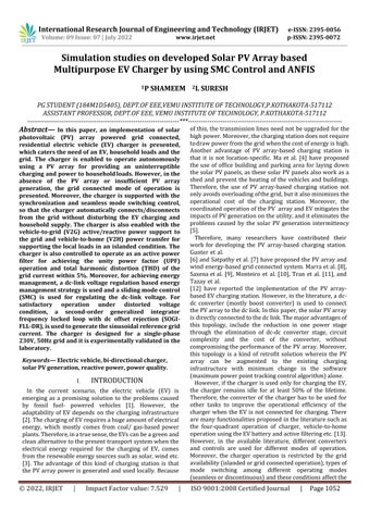
However, the vehicle to grid (V2G) active and reactive powers,vehicle to home(V2H)modesarecoveredinthese two main controls. Moreover, the combined bi directional dc dc converter control for both islanded and grid connectedmodesarealsodiscussed.
The control objective is to charge the EV and supply the household load uninterruptedly irrespective of any disturbance. Therefore, the control is designed such that the multifunctional operation is achieved. The control is mainly divided into islanded and grid connected mode (GCM) as shown in Fig. 3 The maximum generated power from the solar PV array. The charger is connected to the grid through the coupling inductor(Lc).Itisneededtoeliminatetheharmonicsandto smoothen the grid current. A ripple filter is also connected at the PCC (Point of Common Coupling) to prevent the injection of switching harmonics generated by the VSC into thegrid.
The purpose of GCM mode is to regulate the dc link voltageandthecontrolthegridcurrentforcontrollingthe active and reactive power flow, thereby generating the switching pulses for the VSC. The sliding mode control (SMC)andVSCcontrolareexplainedasfollows.
In this work, SMC is utilized for regulating the dc link
voltageand maximumpowerpointtracking(MPPT)ofthe solar PV array. The dc link voltage regulation is also requiredfortheMPPT of the solar PV array, as in single stage topology the
Grid Available
Disable charger
Can EV discharge ? Y
Derate MPPT Regulate DC link voltage at increased V*
Regulate DC bus voltage at Vmpp using BDDC PV operate at MPP
Can EV discharge ? Y V2H Can EV discharge Regulate DC
PCC cb PV operate at MPP Regulate DC link voltage at Vmpp using VSC
Regulate DC bus voltage at Vmpp PV operate at MPP Regulate DC bus voltage at 360V discharge the EV PV operate at MPP Regulate DC bus voltage at Vmpp using VSC
Can EV N discharge bus dc discharge theEV PV operate at MPP
Draw power from grid Charge the EV
Load regulation PV operate at MPP
International Research Journal of Engineering and Technology (IRJET) e-ISSN: 2395-0056
Volume: 09 Issue: 07 | July 2022 www.irjet.net p-ISSN: 2395-0072
MPPT is achieved by regulating the dc link voltage at the voltageofthesolarPVarray.TheMPPTalgorithm estimates the reference dc link voltage (Vdc * ) at which the peakpowerofthesolarPVarrayisextracted.However,inthe absence of the solar PV generation, the dc link voltage is regulatedataspecificvoltage(360V). Duetothepresenceof(σ+δ)sign(S)in(16),thechattering phenomenon may appear with the used SMC control. The


chatteringcannotbefullyeliminatedwiththeusedSMC control. However, the chattering has been restricted to a certain frequencybydefiningthelowestallowablesteady state error by defining the value of δ such that the (σ+δ) doesnotbecomevery small. Since σ is a positive constant, theδisdefinedas, 0.1V
2) VSC Control in GCM ve 0.1V (17)
VSC control is shown in Fig. 3. Due to the non linear household loads and the EV, the grid current contains harmonics. Moreover, the power factor (PF) also deteriorates.Therefore,forimprovingthePFandensuring the grid current THD within 5%, a second order generalized integrator frequency locked loop with dc rejection capability (SOGI FLL DR) [54] is used to estimate the fundamental load current so that the reference current becomes free of harmonics. Fig. 3 shows the extraction of fundamental active load current Using reference active grid current (ip) and
Hysteresis Controller S1 S2 S3 S4
Thereal(Ip)andreactive(Iq)componentsaremultiplied withthein-phase(ut)andthequadrature-phaseunit template(qt)to
International Research Journal of Engineering and Technology (IRJET)
7
|
e-ISSN: 2395-0056
2022 www.irjet.net p-ISSN: 2395-0072
obtain instantaneous reference active grid current (ip) and instantaneous reference reactive grid current (iq), and it is given as,
ip Ip
v gp , q v gq
t t tm tm
i i (24) g p q
B. VSC Control in Islanded Mode © 2022, IRJET | Impact Factor value: 7.529 | ISO 9001:2008 Certified Journal | Page1057
In islanded mode, the objective of the integrated system is to charge the EV and supply the household load autonomously using the PV array energy. Moreover, the V2H power transfer is utilized to feed the household load intheabsenceofthePVarrayenergy.Inislandedmode,the VSC is controlled to operate as an inverter to supply the load as per the control shown in Fig.3 Forthis,thecontrollergeneratesthevoltageusingthe referencefrequencyandreferencevoltageasshowninFig.3 Using the sensed voltage and the reference voltage, the pulses for the VSC are generated. While operating in the islanded mode, the charger needs to be connected to the grid for two-way
voltage,frequencyandphase,tothegridvoltage,frequency and phase. So that the connection to the grid becomes seamless automatic. Therefore, the controller estimates the phase angles of the PCC voltage and grid voltage and calculates thephase error betweentwovoltages.ThePI controller is
International Research Journal of Engineering and Technology (IRJET) e-ISSN: 2395-0056
The combined control of the bi directional dc dc converter for islanded and grid connected is exhibited in Fig. 4. In GCM, the EV battery is charged in constant current/constantvoltage(CC/CV)modeandthecascadePI controller loop is used to control the charging of the EV battery. The outer PI controller controls the terminal voltage of the EV battery and gives the reference battery current for the current control. The reference current usingaPIcontrollerisgivenas, I * (r) I * (r 1) k {V (r) V (r 1)} k V (r) (25)
Where Veve isthedc linkvoltageerrorand kpv, kiv arethe gainsofthePIcontroller.
For V2G power transfer, the reference current for dischargingtheEVbatteryisgivenbytheuser.Thepointto notehereis that the sign of reference EV current for V2G mode is opposite of the G2V mode. Now using the referenceEVcurrentandthesensedEVcurrents,theerror intheEVcurrentiscalculatedandtheinnerPIcontrolgives the duty cycle of the bi directional dc dc converter. The dutycycleiscalculatedas, de (r) d * (r 1) k {I (r) I (r 1)} k V (r) (26)
Where Ieve isthecurrenterrorand kpi, kii arethegainsof thecontroller.
In islanded mode, the bi directional dc dc converter is usedto regulatethe dc link voltage. Moreover,theMPPof thesolarPVarrayisalsoachievedbyregulatingthedc link voltage. For this, the MPPT algorithm gives the reference voltage of the dc link for the MPP operation. However, in the absence of the PV array (V2H), the dc link voltage is regulatedataspecifiedvoltage(V* =360V)asshowninFig. 4.Inthisconditionalso,cascadedPIcontrolisusedwhose outerloopregulatesthedc linkvoltage and the inner loop controls the EV charging/discharging current. The expressionoftheouterloopisgivenas,
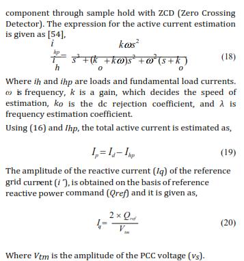
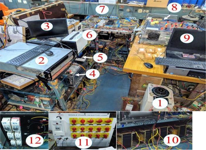
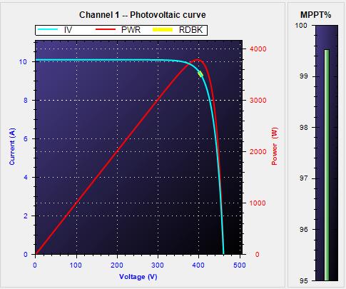
The EV charger designed for single phase 230V, 50Hz grid is shown in Fig. 5. The open circuit voltage and short circuit current of the solar PV array is 460V and 10A, respectively. However, the maximum power point voltage andcurrentare396Vand9.5A,respectively.Thelead acid battery of 240V, 35Ah is used as an EV battery in the experimental prototype. The implementation of the chargeriscarriedoutusingthedigitalcontroller(dSPACE 1006). For the implementation of the control algorithm, the digital controller requires various (voltage and current) signals of the charger. Therefore, various voltage and current signals (analog) are acquired using the Hall Effect based voltage (LEM LV 25P) and current (LEM LA 55P) sensor. These signals are converted into digital signals using an analog to digital converter (ADC). The digital controller uses the digital signal to implement the control algorithmand togenerate theswitchingpulses for VSCanddc dcconverter.
The performance of the charger is shown in Figs. 6 13. Theperformanceofthechargerisevaluatedinbothsteady state and dynamic conditions. The steady state performance of the chargerispresentedforthecasewhen thesolarPVarrayenergyisusedtochargetheEV,feedsthe local household load and supports the grid with surplus power. The dynamic performance of the charger is presented for various operating modes in both islanded andgridconnectedconditions.Duringimplementation,the solar PV array power (PPV), the power drawn from the grid (Pg), and the power drawn from the EV (PEV), are considered positive. However, the power fed into the grid, power drawn by the load and power drawn for EV chargingisconsiderednegative.
A. Steady State Performance of Charger
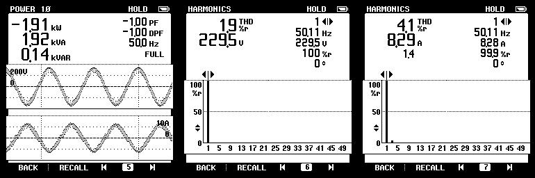
Fig. 6 shows the experimental results in a steady state condition. The steady state behaviour of the charger is presented for the GCM, when the solar PV array power (Ppv) is used for EV charging, powering the local load and supportingthegridwiththesurpluspower.
Where Vde is the voltage error. However, the gains of the controllerare kpd and kid.
Now, (26) gives the duty cycle using reference and the sensed current. After this, the PWM generator gives switchingsignalsfortheconverter.


International Research Journal of Engineering and Technology (IRJET) e-ISSN: 2395-0056
Volume: 09 Issue: 07 | July 2022 www.irjet.net p-ISSN: 2395-0072
Figs.6(a) (b)showthatthesolarPVarrayisgenerating 3.77kW. Out of 3.77 kW, 0.8kW is taken by the household load (Ph) and 0.95kW is used by the EV for charging. Remaining 1.91kW is fed into the grid at UPF. The voltage (VPV),current(IPV)andpower(PPV)ofthesolarPVarray are shown in Figs. 6(a) (b). The voltages, currents and powersoftheloadandtheEVbatteryareshowninFigs.6 (c) (d)andFigs.6(j) (k).Thevoltage(vg),current(ig),and power of the grid (Pg) are shown in Figs. 6 (e) (f). The chargerisnotinjectinganyvoltageandcurrentharmonics intothegridasshownbythegridvoltage(vg),gridcurrent (ig)andloadcurrent(ih),total harmonic distortion(THD) in Figs. 6 (g) (i). Moreover, it is also not drawing any reactive power from the grid as justified by the unity displacement power factor (DPF) operationofthe charger inFig.6(f).Fig.6(l) (m)showtheVSCparameters.
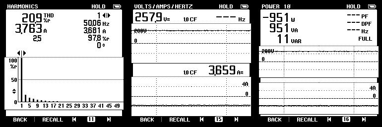
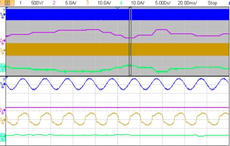
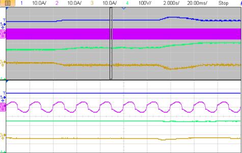
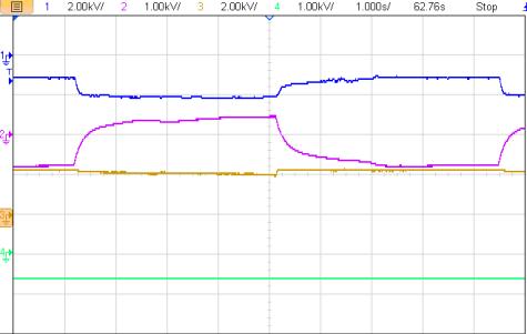
The islanded mode of the charger is presented to show the charger capability to operate autonomously using the solarPVarrayenergyforprovidingthechargingfacilityto the EV and supply to the household load. During the islanded mode of operation, the household load changes along with the solar irradiance. Therefore, the charger performanceunderthese disturbancesispresentedinFig. 7. Initially, the solar PV array charges the EV and feed the householdloadasshownbythenegativeEVcurrentinFig. 7(a). However, after some time, the solar PV array generation(Ppv)becomeszero.Therefore,tofeed the load uninterruptedly, the EV battery starts discharging, to support the home loads, as shown by the positive battery current (Iev) in Fig. 7 (a). This mode is called vehicle to home. Fig. 7 (b) shows the voltage generated at the PCC (vs) using the charger. Moreover, the non sinusoidal load current(ih)isalsoexhibitedinFig.7(b).Fig.7(b)exhibits that during solar irradiance change the PCC voltage (vs), loadcurrent(ih)anddc linkvoltage(Vdc)areundisturbed.
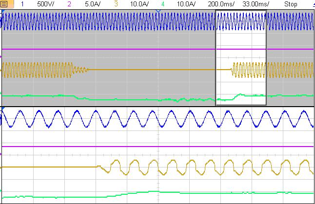
The islanded operation under load change is shown in Figs. 7(c) (d). Here, the load is changed in step over a wide range. The dc link voltage is maintained by the bi directional dc dc converter, the load change is compensated bytheEV battery.Becauseof which,theEV battery charging changes with the load change. However, the solar PV array generation (Ppv) and the dc link voltage(Vdc)arenotaffectedbytheloadchange.Fig.7(d) also shows that the connection/disconnection of the householdloadisnotdisturbingthePCCvoltage.Fig.7(d) showsthatwhentheloadisdisconnected,thewholesolar PV array power (Ppv) is stored into the EV battery. However, the MPP operation of the solar PV array is not affected.
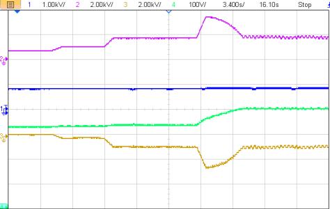
InFigs.7(e) (f),thesolarirradianceischangedinsteps, keeping the household constant. Initially, with the increase in solar irradiance, PV power increases. As a result,thepowerstoredintheEVbatteryalsoincreasesto maintain the active power balance. However, when the solar irradiance is increased from 500W/m2 to
1000W/m2, the solar PV array generation does not increasebecausethecontrollerincreasesthereferencedc link voltage to achieve the MPPT derating as the charging rateofEVisrestrictedbythecontrollerasshowninFig.7.
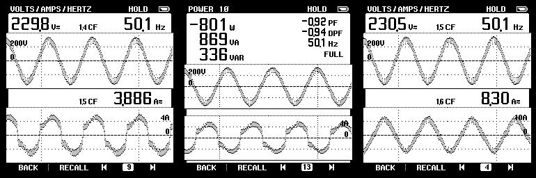
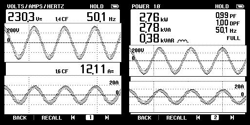
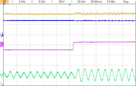
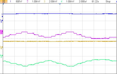
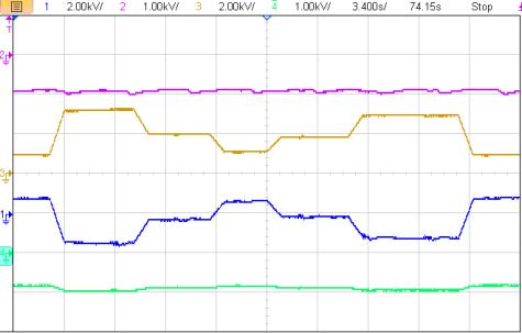
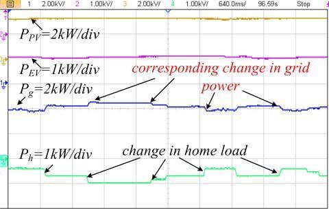
Thechargeroperatesingridconnected modeeitherdue tothe excess power generation or power scarcity. In both cases, the charger exchanges the power with the grid at unitypowerfactor.However,ingridconnectedmodealso, many disturbances occur during the operation. Therefore, the stable operation of the charger under these operating condition is required. The behaviour under the load perturbationinGCMisshowninFig. 8. Ingridconnected mode, the dc link voltageis regulated by the voltage source converter of the charger, therefore, the load changeonlyaffectsthegridpower.Here,theload ischangedin steps and the corresponding change in grid power (Pg) can be seeninFig.8(a).Thereductioninload current (ih) is causing an increase in grid current (ig) as showninFig.8(b).However,thePVarraycurrent(Ipv)and the EV charging current (Iev) are not affected by the load change.Thesameisjustified by theundisturbedPVarray (Ppv)andtheEVpower(Pev).Thevoltageacrossthedclink (Vdc) is also regulated during the load change. The performance under solar irradiance change is shown in Figs. 8(c) (d). Due to the change in the solar irradiance level, the PV array generation (Ppv) changes. Since the household loads and the EV charging should not be disturbed by the irradiance change, the grid power (Pg) changes to maintain the power balance. The solar irradiance is changed in step from 1000W/m2 to 700W/m2, 700W/m2 to 300W/m2 and so on. Due to this, the grid power (Pg) becomes both positive and negative. That means, at 1000W/m2 , the excess generation is supplied back to the grid. However, at 300W/m2 , the power is drawn from the grid. The EV power (Pev), load power(Ph)anddc link voltage (Vdc) remain undisturbed.
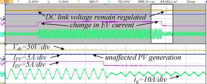
In GCM, the EV charger participates in demand based active power exchange with the grid. Therefore, the EV voluntarily takes active power from the grid or discharges someofitsstoredenergytothegridasshowninFigs.8(e) (f). Due to the charging /discharging of the EV battery, the grid power (Pg) changes without affecting the PV array generation (Ppv) and the load supply (Ph). Figs. 8(e) (f) show the step change in the battery current (Iev) from charging to discharging. Due to the discharging of the battery, the grid current (ig) increases. However, the PV array current (Ipv) and the dc link voltage (Vdc) remain unaltered. Therefore, from the dynamic results, it is observed that the charger operation in grid connected and islanded mode are not affected by the disturbances. Moreover,itisalsoperceived thatonetypeofperturbation isnotinterferingwiththeoperationofanothercomponent.
Fig. 9 shows the V2G reactive power performance at Pg=0kW. Due to the step change in the reference reactive power(Qref) from 1kVAR to 1kVAR, the grid current (ig) becomesleadingfromlagging.Moreover,thedc linkvoltage
(Vdc)remainsundisturbed.
Fig. 10 shows the harmonic compensation and PCC voltagecorrectioncapabilityofthecharger.Fig.10shows that the grid current (ig) is the same as load current (ih)
PV to home+EV Vehicle to home
Vdc=500V/div
Ph=1kW/div PV generation become zero
PPV=2kW/div
PEV=1kW/div
=5A/div
without harmonics mitigation using VSC. However, it is observed that the grid current (ig) becomes sinusoidal afterharmonicscompensation.Thecurrent(is)ofVSCis
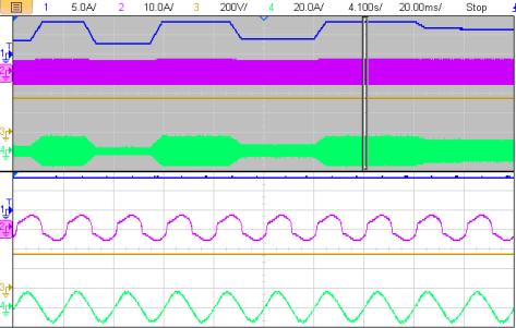
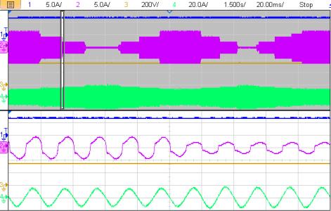
Change in PV power Vdc=500V/div
PEV=2kW/div Corresponding change in EV power EV supports the demand


vs=500V/div I =5A/div
PPV=2kW/div Ph=1kW/div Change in home load EV support the home load ih=5A/div IEV=5A/div
(a) (b) (c) (d) (e) (f)
1000W/m MPPT derating Ih=10A/div Ph=2kW/div
change in home load demand
corresponding change in grid power
IPV=5A/div ih=5A/div
Vdc=200V/div ig=20A/div
Fig. 7 Dynamic performance in islanded condition, (a) (b) under solar irradiance change, (c) (d) under the change in household load, (e) (f) derating of MPPT (a) (b) (c) (d) (e) (f)
Fig.8Dynamicperformanceingridconnectedmode,(a) (b)underchangeinhouseholdload,(c) (d)underchangeinsolar irradiancepower,(e) (f)underchangeincharging/dischargingofEVbattery
leading from lagging. Moreover, the dc link voltage (Vdc)remainsundisturbed.
Fig. 10 shows the harmonic compensation and PCC voltage correction capability of the charger. Fig. 10 shows that the grid current (ig) is the same as load current (ih) without harmonics mitigation using VSC.
However, it is observed that the grid current (ig) becomessinusoidalafterharmonicscompensation.The current (is) of VSC is shown in Fig. 10. Moreover, it is observed that the PCC voltage (vg) profile also improves due to compensation
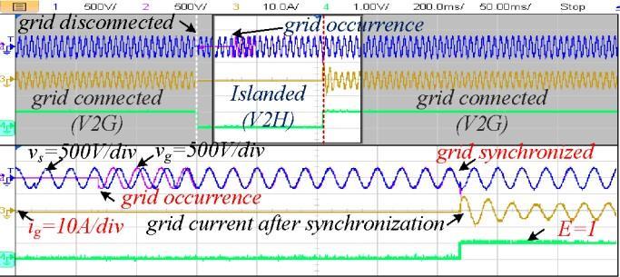
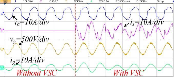
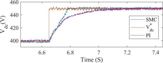
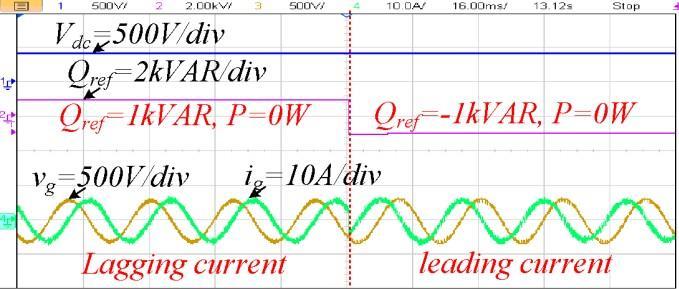
Fig. 12 shows the dc link voltage (Vdc) regulation capability of the PI controller and SMC under the step changeof50Vinreferencedc linkvoltage(V* ).FromFig. 12,itis observedthat the SMC is faster in regulating the dc linkvoltageascomparedthePIcontrol.
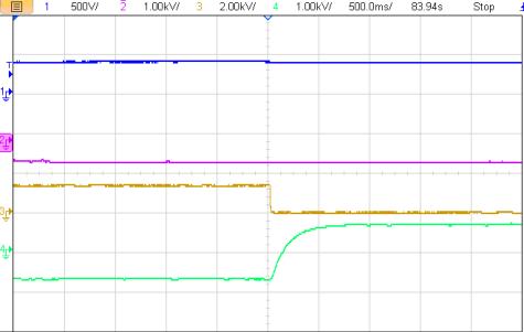
Due to sudden variation in EV current (Iev) from discharging to charging, the dc link voltage (Vdc) is not regulated with the PI control, as shown in Fig. 13 (a). However,theSMCcontrolhasregulatedthedc linkvoltage (Vdc) at the sudden change, as shown in Fig. 13 (b). Since thePVarrayMPPoperationdependsonthedc linkvoltage regulationatMPPvoltage;thePVarraydoesnotoperateat MPPdueto thesteady state errorin PIcontrol.Moreover, it also changes under the sudden change in EV current. However, with SMC, the steady state error is always zero and it also does not change with EV current change. Therefore,italwaysoperatesatMPP.
dc
AnintegratedchargerwithsolarPVarray,householdload and grid has been implemented using the IGBT switches based converters, solar simulator, EV battery, dSPACE (1006) controller and the test results have verified the simultaneous EV charging and household supply in both islandedandgridconnectedmodes.Fromthesetestresults, it is observed that this charger is performing its specified task ofEV charging,supplyinglocal loadsand maintaining the power quality at the grid side. Moreover, the islanded operation with voltage THD less than 5% and vehicle to home operation using solar PV array is also verified. The demand based reactive power support and the active power filtering using VSC are also validated through test results. The smooth transition from islanded to grid connectedmodeandviceversaareverifiedbytestresults.
International Research Journal of Engineering and Technology (IRJET) e-ISSN: 2395-0056
Volume: 09 Issue: 07 | July 2022 www.irjet.net p-ISSN: 2395-0072
[1] J. R. Aguero, E. Takayesu, D. Novosel and R. Masiello, “ModernizingtheGrid:ChallengesandOpportunitiesfor aSustainableFuture,” IEEE Power and Energy Magazine, vol.15,no.3,pp.74 83,May June2017.
[2] D.Bowermaster,M.AlexanderandM.Duvall,“TheNeed for Charging: Evaluating utility infrastructures for electric vehicles while providing customer support,” IEEE Electrifi. Mag.,vol.5,no.1,pp.59 67,2017
[3] X.LuandJ.Wang,“AGameChanger:ElectrifyingRemote Communities by Using Isolated Microgrids,” IEEE Electrifi. Mag.,vol.5,no.2,pp.56 63,June2017.
[4] T.Ma and O. A.Mohammed, “Optimal Charging of Plug in Electric Vehicles for a Car Park Infrastructure,” IEEE Trans. Ind. Applicat., vol. 50, no. 4, pp. 2323 2330, July Aug.2014.
[5] L. Cheng, Y. Chang and R. Huang, “Mitigating Voltage Problem in Distribution System With Distributed Solar Generation Using Electric Vehicles,” IEEE Trans. Sust. Ene,vol.6,no.4,pp.1475 1484,Oct.2015.
[6] S. J. Gunter, K. K. Afridi and D. J. Perreault, “Optimal Design of Grid Connected PEV Charging Systems With Integrated Distributed Resources,” IEEE Trans. Smart Grid,vol.4,no.2,pp.956 967,2013.
[7] O. Erdinc, N. G. Paterakis, T. D. P. Mendes, A. G. Bakirtzis and J. P. S. Catalão, “Smart Household Operation Considering Bi Directional EV and ESS Utilization by Real Time Pricing Based DR,” IEEE Trans. Smart Grid, vol. 6, no. 3, pp. 1281 1291, May 2015.
[8] H.R.Baghaee,M.Mirsalim,G.B.GharehpetianandH.A. Talebi,“ADecentralizedPowerManagement
[9] Z.Yi,W.DongandA.H.Etemadi,“AUnifiedControland Power Management Scheme for PV Battery Based Hybrid Microgrids for Both Grid Connected and Islanded Modes,” IEEE Trans. Smart Grid, vol. 9, no. 6, pp.5975 5985,Nov.2018.
[10] M.KwonandS.Choi,“ControlSchemeforAutonomous and Smooth Mode Switching of Bidirectional DC DC Converters in a DC Microgrid,” IEEE Trans. Power Electronics,vol.33,no.8,pp.7094 7104,Aug.2018.
[11] M. Jafari, Z. Malekjamshidi, J. Zhu and M. Khooban, “Novel Predictive Fuzzy Logic Based Energy Management System for Grid connected and Off grid Operation of Residential Smart Micro grids,” IEEE Journal of Emerging and Selected Topics in Power Electronics,EarlyAccess.
[12] S. A. Singh, G. Carli, N. A. Azeez and S. S. Williamson,
“Modeling, Design, Control, and Implementation of a Modified Z Source Integrated PV/Grid/EV DC Charger/Inverter,” IEEE Trans. Industrial Electronics, vol.65,no.6,pp.5213 5220,June2018.
[13] M. Restrepo, J. Morris, M. Kazerani and C. A. Cañizares, “Modelingand Testingof a Bidirectional SmartCharger for Distribution System EV Integration,” IEEE Trans. Smart Grid,vol.9,no.1,pp.152 162,2018.
[14] J. Y. Yong, V. K. Ramachandaramurthy, K. M. Tan and J. Selvaraj,“ExperimentalValidationofaThree PhaseOff Board Electric Vehicle Charger With New Power Grid Voltage Control,” IEEE Trans. Smart Grid, vol. 9, no. 4, pp.2703 2713,July2018.
[15] M. Nikkhah Mojdehi and P. Ghosh, “An On Demand Compensation Function for an EV as a Reactive Power ServiceProvider,” IEEE Trans. Vehicular Technology,vol.65, no.6,pp.4572 4583,June2016
[16] U. R. Prasanna, A. K. Singh and K. Rajashekara, “Novel Bidirectional Single phase Single Stage Isolated AC DC Converter With PFC for Charging of Electric Vehicles,” IEEE Trans. Transportation Electrification, vol. 3, no. 3, pp.536 544,Sept.2017.
[17] D. B. Wickramasinghe Abeywardana, P. Acuna, B. Hredzak, R. P. Aguilera and V. G. Agelidis, “Single Phase Boost Inverter Based Electric Vehicle Charger With Integrated Vehicle to Grid Reactive Power Compensation,” IEEE Trans. Power Electron., vol. 33, no. 4,pp.3462 3471,April2018.
[18] N. Mehboob, M. Restrepo, C. A. Cañizares, C. Rosenberg and M. Kazerani, “Smart Operation of Electric Vehicles With Four Quadrant Chargers Considering Uncertainties,” IEEE Trans. Smart Grid, vol. 10, no. 3, pp. 2999 3009,May2019.
[19] F. Berthold, A. Ravey, B. Blunier, D. Bouquain, S. Williamson and A. Miraoui, “Design and Development of a Smart Control Strategy for Plug In Hybrid Vehicles Including Vehicle to Home Functionality,” IEEE Trans. Transportat. Electrification,vol.1,no.2,pp.168 177,Aug. 2015.
[20] H.N.deMelo,J.P.F.Trovão,P.G.Pereirinha,H.M.Jorge and C. H. Antunes, “A Controllable Bidirectional Battery Charger for Electric Vehicles with Vehicle to Grid Capability,” IEEE Trans. Vehicular Technology,vol.67,no. 1,pp.114 123,Jan.2018.
[21] H. Mahmood and J. Jiang, “Autonomous Coordination of Multiple PV/Battery Hybrid Units in Islanded Microgrids,” IEEE Trans. Smart Grid, vol. 9, no. 6, pp. 6359 6368,Nov.2018.
[22] P.Lin, P. Wang,C. Jin,J. Xiao,X.Li,F.Guo,andC. Zhang., “A Distributed Power Management Strategy for Multi Paralleled Bidirectional Interlinking Converters in
International Research Journal of Engineering and Technology (IRJET) e-ISSN: 2395-0056
Volume: 09 Issue: 07 | July 2022 www.irjet.net p-ISSN: 2395-0072
Hybrid AC/DC Microgrids,” IEEE Trans. Smart Grid, vol. 10,no.5,pp.5696 5711,Sept.2019.
[23] M.O.BadawyandY.Sozer,“PowerFlowManagementof a Grid Tied PV Battery System for Electric Vehicles Charging,” IEEE Trans. Industry Applications, vol. 53, no. 2,pp.1347 1357,March April2017.
[24] Q. Yang, L. Jiang, H. Zhao and H. Zeng, “Autonomous Voltage Regulation and Current Sharing in Islanded Multi Inverter DC Microgrid,” IEEE Trans. Smart Grid, vol.9,no.6,pp.6429 6437,2018.
[25] V. Monteiro, J. G. Pinto and J. L. Afonso, “Operation ModesfortheElectricVehicleinSmartGridsandSmart Homes: PresentandProposedModes,” IEEE Trans. Veh. Techno.,vol.65,no.3,pp.1007 1020,2016.
[26] S. Boudoudouh and M. Maaroufi, “Renewable Energy Sources Integration and Control in Railway Microgrid,” IEEE Trans. Ind. Appl., vol. 55, no. 2, pp. 2045 2052, March April2019.
[27] C. Luo, Y. Huang and V. Gupta, “Stochastic Dynamic Pricing for EV Charging Stations With Renewable Integration and Energy Storage,” IEEE Trans. Smart, “Operational Value Based Energy Storage Management for Photo Voltaic(PV) Integrated Active Power Distribution Systems,” IEEE Trans. Ind. Appl., EarlyAccess.


L Suresh was born in Tiruchanoor (AP), India, in 1987. He received B. Tech. degree in Electrical and Electronics Engineering from Siddharth Institute of Engineering and Technology ,Puttur (AP), India,in2009and M.Tech.degreeinPower Electronics & Electrical Drives from SVPCET, Puttur in 2013. He is currently working as a Assistant Professor in Department of Electrical Engineering, VEMUInstituteof Technology,P.Kothakota, Chittoor. His areas of interests include electric vehicle, renewable energy based charging infrastructure, power electronics, renewable energy, micro grid, and power quality.He has more than 12 years of experienceinteaching.
P Shameem currently persuing M.Tech(PE&ED) bearing roll no 184M1D5405 in Vemu Institute of Technology, P.Kothakota Chittoor.Her areas of interest are Control Systems and PowerElectronics
| Impact Factor value: 7.529 | ISO 9001:2008