International Research Journal of Engineering and Technology (IRJET) e ISSN: 2395 0056

Volume: 09 Issue: 07 | July 2022 www.irjet.net p ISSN: 2395 0072
International Research Journal of Engineering and Technology (IRJET) e ISSN: 2395 0056
Volume: 09 Issue: 07 | July 2022 www.irjet.net p ISSN: 2395 0072
1Arshamol Sulaiman, Mtech, Structural Engineering, Ilahia college of engineering and technology, Muvattupuzha, Kerala, India.
2Biby Aleyas, Assistantprofessor, Ilahia college of engineering and technology, Muvattupuzha, Kerala, India. ***
Abstract Tall buildings are now widely constructed in all over the world. The construction materials strength is the key factor to build the high rise structures. Concrete has compressive strength, stiffness and stability whereas steel has tensile strength, ductile behavior but both of those behaviors are not found in one material. As a result the composite materials are required to build tall buildings. The combined behavior of steel and concrete is reduced the member size and provide more strength for constructing tall buildings. Steel is widely used as reinforcement in reinforced concrete structure.
Recently, concrete filled steel tubular (CFST) columns have been widely used in tall buildings due to their significant advantages in structural performance and ease of construction. A new type of fabricated coupled composite column (CCC) system composed of closely spaced double small section concrete filled steel tubes (CFST) connected by steel connector beams. The infilled concrete prevents the inward local buckling of the steel tube, whilst the steel tube provides confinement to the concrete. Composite columns can have high strength for a relatively small cross sectional area.By using this fabricated coupled composite column it gives an extra protection during earthquakes. If one column of the coupled composite column is failed during seismic action or some other high intensity force ,the other column of CCC withstand the structure. If the beam connector between the two composite column is failed during seismic action or some other forces ,it must be replaced byanotherbeam connector because of the usage of bling bolts. To analyse the steel members, three dimensional (3D) modeling, buckling and seismic action of building were applied, using ETAB software.
Key Words: Fabricated coupled composite column, Concrete filled steel tubes, Fabricated structure, Connectorbeams,Seismicperformance.
A new type of fabricated coupled composite column (CCC) system composed of closely spaced double small section concrete filled steel tubes (CFST) connected by steelconnectorbeamsusingblindboltswasproposed.The
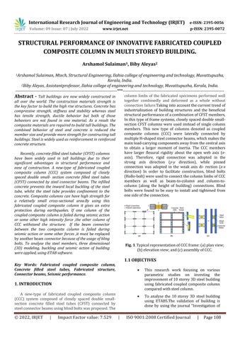
column limbs of the fabricated specimens performed well together combinedly and deformed as a whole without connectionfailure.Takingintoaccountthecurrenttrendof industrialization of building structures and the beneficial structuralperformanceofacombinationofCFSTmembers, Inthistypeofframesystems,closelyspaceddoublesmall section CFST columns were used instead of single column members. This new type of columns denoted as coupled composite columns (CCC) were laterally connected by multipleH shapedsteelconnectorbeams,whichmakesthe mainload carryingcomponentsawayfromthecentralaxis to obtain a larger moment of inertia. The CCC members have larger flexural rigidity about the open web axis (x axis). Therefore, rigid connection was adopted in the strong axis direction (y y direction), while pinned connection was adopted in the weak axis di rection (x x direction) In order to facilitate construction, blind bolts (Hollo bolt)wereusedtoconnectthecolumnlimbsofCCC members as well as beam to column and column to column (along the height of building) connections. Blind bolts were found to be easy to install and tightened from onesideoftheconnection.
Fig. 1 TypicalrepresentationofCCCframe:(a)planview; (b)elevationview;and(c)assemblyofCCC.
This research work focusing on various parametric studies on investing the improvementof10storey3Dsteelbuilding using fabricated coupled composite column comparedwithsteelcolumn.
To analyse the 10 storey 3D steel building using ETABSThe validation of building is done by using the journal “Investigation of
International Research Journal of Engineering and Technology (IRJET) e ISSN: 2395 0056
Volume: 09 Issue: 07 | July 2022 www.irjet.net p ISSN: 2395 0072
the seismic behaviours of three dimensionalhigh risesteelframestructures equipped with oil dampers with variable stiffness”. Collect the earthquake records fromPEERdatabase.
To examine the horizontal ground motion records of the imperial Valley have been selected for performing the TH analysis. Modeling the fabricated coupled composite columnsusingETABS.
To Investigate buckling strength of an structure and load at which buckling takes place performance by varying parameters such as buckling load with varying link( 2link,3link,4linkand5link),bucklingload with varying cross section( 120mm, 140mm, 160mm, 180mm, 200mm) and buckling load with varying grade of concrete(M30andM40).
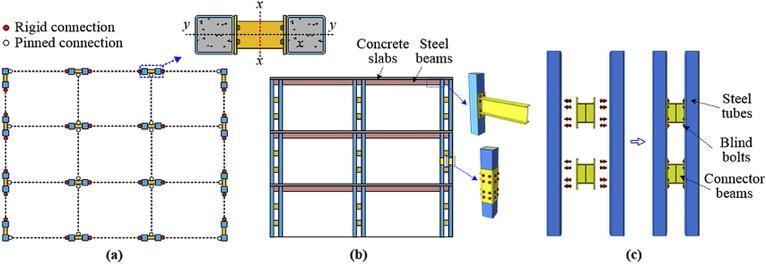
Analyses are performed for the 10 story three dimensional steel frame structures using Imperial valley ground motions analyzed using the ETAB software . The structurehavethreespansinthehorizontaldirections,the spanlength is5m,andthestoryheightofthestructureis 3.2m Arrangementsofthebeamsandcolumnsareshown in Table 1and Table2 Slab thickness is 130 mm. The concrete mix defined for the column, beam/slab is taken as M30 and M40 respectively. Fe 500 and Fe 415 grade rebarisuse1 §dasalongitudinalandconfinementbar
Table 1: Typesandsizesofbeamsandcolumns
BE AM TO TAL DEP TH
WEB THICK NESS
Examine the effective models from the buckling analysis,and implementing to the building.To estimate seismic structural deformations and seismic capacity of structures by placing the coupled columns in various conditions such as only at interior, only at exterior, only at corners, along with two interior sides, zigzag position, diagonal shape, two side exterior, four side centre exterior and alternative vertical. To perform various parametric study on 3D building by Replacing coupled composite column instead of conventional column.
Comparing the seismic parameters such as base shear, storey displacement and comparedwithconventionalstructure.
TOP FLA NGE WID TH
TOP FLANG E THICK NESS
COL UMN TO TAL DEP TH
FLANG E THICK NESS
b1 0.45 0.01 0.225 0.02 c1 0.45 0.03 b2 0.4 0.01 0.225 0.02 c2 0.4 0.025 b3 0.35 0.0088 0.225 0.02 c3 0.35 0.025 b4 0.3 0.008 0.2 0.015 c4 0.3 0.02 c5 0.25 0.015
Table 2: Beamandcolumntypeofstructure
BUILDING STORIES BEAMS COLUMNS
10 STOREY 1 4 b2 c3 5and6 b3 c3 7and8 b3 c4 9and10 b4 c4
Theworkislimitedtocombiningintegrated compositesteelbuildings.
Theseismicanalysisbymeansoftimehistory analysisthatweuseandnootheranalysisisdone.
Examine the horizontal ground motion records of the imperial Valley have been selected for performing the TH analysis. Investigatebucklingstrengthofanstructureand loadatwhichbucklingtakesplaceperformancebyvarying parameters.Examine the effective models from the buckling analysis,and implementing to the building. To estimate seismic structural deformations and seismic capacity of structures by placing the coupled columns in variousstories.AnalysisisdonebyusingETABS.
value:
For the validation of the model, “Investigation of the seismic behaviours of three-dimensional high-rise steel frame structures equipped with oil dampers with variable stiffness” journal paper is selected. Model is analysed by the software ETABS by using TIME HISTORY ANALYSIS.Inthisthesis, 10 story3Dsteelbuildingunder time history analysis in ETABS 2019 for studying the effectivenessofseismicresponseintheformofbaseshear, story displacements . The horizontal ground motion recordsofRSN:174,ImperialValley 06fromPEERground motion data base have been selected for performing the nonlineardynamicTHanalysis.
International Research Journal of Engineering and Technology (IRJET) e ISSN: 2395 0056
Volume: 09 Issue: 07 | July 2022 www.irjet.net p ISSN: 2395 0072
fig 5.8 shows the dynamic displacement curves of the 10 story structure in the X and Y directions at the top of the structure with the Imperial Valley ground motion using ETABS. The peak displacements of the 10 story structure in the X and Y directions are 338.99mm and 172.73mm respectively.
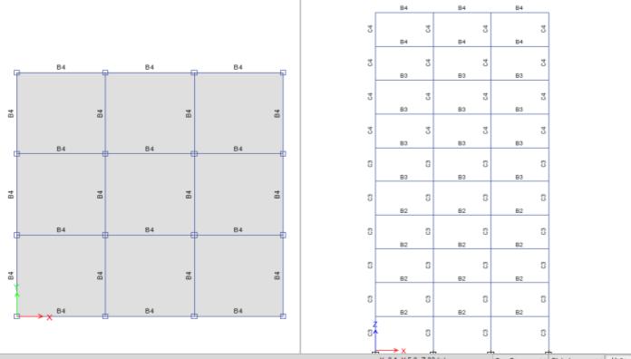
Fig 2:Planandelevationviewofbuilding
Fig.2andFig3showsthedynamicdisplacementcurvesof the10storystructurein the Xand Ydirections atthetop of the structure with the Imperial Valley ground motion. The peak displacementsofthe10 storystructure in the X andYdirectionsare0.313mand0.177mrespectively.
Fig -4:Timehistoryanalysisresultsforthedisplacement oftopstoreyinX direction
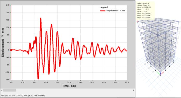
Fig 2:TimehistoryloadfunctioninX direction(PGA)
Fig 5:Timehistoryanalysisresultsforthedisplacement oftopstoreyY direction
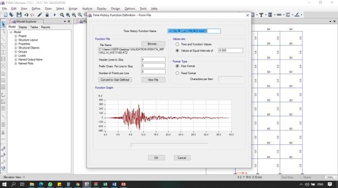
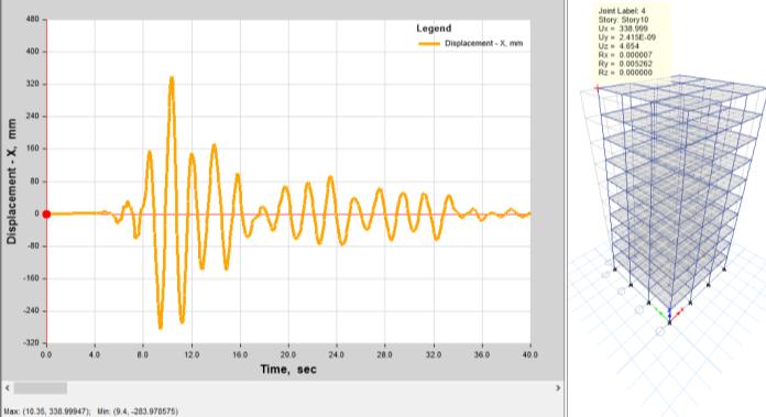
Table 3: Validationresultcomparison X Y JOURNAL 313 177 ETABS 338 172.3 DIFFERENCE(%) 7.99 2.66
Percentage of difference obtained is less than 10 percentage,hencevalidationissuccessful.
Fig 3: TimehistoryloadfunctioninY direction(PGA)
The time taken for vibrating the building during earthquakeinY directionis1.877seconds.Thefig5.7and
5.1ANALYSIS OF BUCKLING LOAD WITH VARYING LINK
Buckling load is analysed in coupled composite column withvaryinglinksuchas2link,3link.4linkand5link.That
International Research Journal of Engineering and Technology (IRJET) e ISSN: 2395 0056
is steel connector between the two composite column is changed by their number. Then comparing the CCC result with the conventional steel column under buckling load.The conventional steel column properties are taken fromthebeamcolumndescriptionfromthebasejournal.
Table 4: Comparisonofbucklingloadwithvaryinglink
MODEL MAJOR AXIS (X DIRECTION) MINOR AXIS (Y DIRECTION)
BOXSECTION 346115.42 346115.52
CCC 2(100mm) 33321.88 41356.29
CCC 3(100mm) 33167.99 43087.12
CCC 4(100mm) 33118.75 44876.22
CCC 5(100mm) 33098.47 46669.13
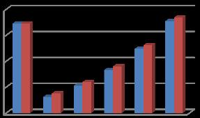
Buckling load is analysed in coupled composite column with varying cross section such as 120mm, 140mm, 160mm, 180mm, 200mm. Then comparing the CCC result with the conventional steel column under buckling load. The conventional steel column properties are taken from the beam column description from the base journal. The coupled composite column consisting of concrete using M30gradeconcrete
Table 5: Comparisonofbucklingloadwithvaryingcross section
MODEL MAJORAXIS(X DIRECTION) MINORAXIS(Y DIRECTION)
BOXSECTION 346115.42 346115.52
CCC 120mm (M30) 61628.35 75441.42
CCC 140mm (M30) 103823.83 117721.69
CCC 160mm (M30) 162755.25 176652.02
CCC 180mm (M30) 241632.01 255474.97
CCC 200mm (M30) 343789.56 357538.22
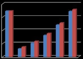
Theconventionalsteelcolumnpropertiesaretakenfrom thebeamcolumndescriptionfromthebasejournal.The coupledcompositecolumnconsistingof concreteusing
M40gradeconcreteandsteeltubecrosssectionisvarying with120mm,140mm,160mm,180mmand200mm.Then comparingtheCCCresultwiththeconventionalsteel columnunderbucklingload.
Table 6: Comparisonofbucklingloadwithvaryinggrade ofconcrete
MODEL MAJOR AXIS (X DIRECTION) MINOR AXIS (Y DIRECTION)
BOXSECTION 346115.42 346115.52
CCC 120mm (M40) 62695.13 76544.95
CCC 140mm (M40) 106036.71 119975.36
CCC 160mm (M40) 166853.34 180795.49
CCC 180mm (M40) 248615.55 262508.96
CCC 200mm (M40) 354951 368760.55
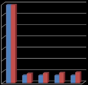
BUCKLING LOAD COMPARISON OF VARYING LINK
0 50000 100000 150000 200000 250000 300000 350000
MAJOR AXIS (X-DIECTION)
MINOR AXIS(YDIRECTION)
Fig 6:Barchartofvaryinglink
Volume: 09 Issue: 07 | July 2022 www.irjet.net p ISSN: 2395 0072 © 2022, IRJET | Impact Factor value: 7.529 | ISO 9001:2008 Certified Journal |
International Research Journal of Engineering and Technology (IRJET) e ISSN: 2395 0056
Volume: 09 Issue: 07 | July 2022 www.irjet.net p ISSN: 2395 0072
CCConlyatexterior
CCConlyatcorners
CCConlyatcentreexterior
CCCinzigzagposition
CCCatalternativeverticalposition
CCCatdiagonalshape
CCCathorizontallengthinterior
CCCattwosideexterior
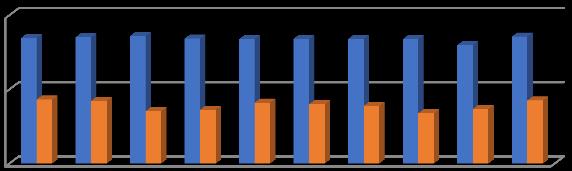
Fig 7:Barchartofvaryingcrosssection
Fig 8:Barchartofvaryinggradeofconcrete
Fromtheanalysisofbucklingload,wehaveconcludedthat thevalueofdisplacementinX directionandY directionof CCC200mmM40isclosertothevalueofboxsection.From the analysis of buckling load with varying parametric conditiontakingthecoupledcompositecolumnwith5link and 200mm cross section using M40 grade concrete as effective model and implementing to the structure for seismicanalysis.
From the analysis of buckling load with various parameters,theeffectivemodelistakenandimplementing to the structure for seismic analysis. In seismic analysis the effective model is implemented instead of some conventional steel columns according to the parametric conditions.Variousparametricstudyareperformedon3D building by Replacing CCC instead of conventional columnsby,
CCConlyatinterior
Effective models from the buckling analysis is implemented and it is a carried to estimate seismic structuraldeformationsandseismiccapacityofstructures by placing the coupled columns in various stories Seismic parameters such as base shear, storey displacement and top storey acceleration are studied and compared with conventional structure. The following fig shows the comparisonofstoreydisplacementofallmodelsinXandY direction,comparisonofbaseshearofallmodelsinXand Y direction, comparison of storey drift of all models in X and Y direction and comparison of time period of all modelsinXandYdirectionwhenbuildingvibratesduring earthquake. Fig
International Research Journal of Engineering and Technology (IRJET) e ISSN: 2395 0056
Volume: 09 Issue: 07 | July 2022 www.irjet.net p ISSN: 2395 0072
2.1
Fig -12:ComparisonoftimeperiodofallmodelsinXandY direction
From the modelling of various parametric study are performedon3DbuildingbyReplacingcoupledcomposite column instead of conventional columns according to the seismic parameters such as base shear, storey displacement and top storey acceleration are studied and comparedwithconventionalstructurewehaveconcluded that coupled composite column placed in the two horizontal interior bays are considered as the perfect modelfortheseismicanalysis.
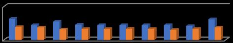
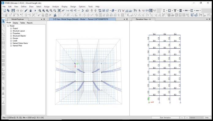
Fig 10:ComparisonofdriftofallmodelsinXandY direction
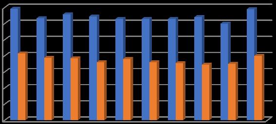

Fig 11:ComparisonofbaseshearofallmodelsinXandY direction
Fig 13:Finalizedmodel
A steel with concrete composite column is fully compression type member, has mainly two type concrete encased in steel section and concrete infilled tube steel sectionandisnormallyusedasaload bearingmemberin a composite structural frame. Concrete infill steel column use the benefit of both material steel as well as concrete. Thisresearchworkfocusingonvariousparametricstudies on investing the improvement of 10 storey 3D steel building using fabricated coupled composite column
International Research Journal of Engineering and Technology (IRJET) e ISSN: 2395 0056
compared with steel column. To analyse the 10 storey 3D steel building using ETABS The analysis was done in two parts.
From the buckling analysis we have concluded that coupled composite column with 5 link,200mm thickness and m40 concretetakenformodelling.
Modelling of various parametric study are performed on 3D building by Replacing coupled composite column instead of conventionalcolumns.
According to the seismic parameters such as base shear, storey displacement and top storey acceleration are studied and comparedwithconventionalstructure.
From the study we have concluded that coupled composite column placed in the twohorizontal interiorbaysareconsidered as the perfect model for the seismic analysis.
From the seismic study result we have concluded that the coupled composite column implemented at horizontal lined interiormodelisbetterthanothermodels.
Thefinalizedmodelingpropertiesare:
The displacement in X and Y direction of composite column placed horizontal length interior model is 5.79% and 14.91% respectivelylowerthanthatofsteelmodel.
The base shear in X and Y direction of composite column placed horizontal length interior model is 33.74% and 14.74% respectivelylowerthanthatofsteelmodel.
The drift in X and Y direction of composite column placed horizontal length interior model is 13.31% and 15.69% respectively lower than that of steel model.
The weight of building reduced from 9241 to 9058.
The percentage of material used during construction is reduced from 1 to 0.8.
[1]L.H.Han,W.Li,R.Bjorhovde,Developmentsand advanced applications of concrete filled steel tubular (CFST): member, J. Constr. Steel Res. 100 (2004) 211 228.
[2] H.S.Hu,Y.Liu,B.T.Zhuo,Z.X.Guo,B.M.Shahrooz,Axia lcompressivebehaviorof square CFST columns through direct measurement of load components, J. Struct. Eng. 144(11)(2018),04018201.
[3]Y.Wei,C.Jiang,Y.F.Wu,Confinementeffectivenessofc ircularconcrete filledsteel tubular columns under axial compression,J.Constr.SteelRes.158(2019)15 27.
[4] Z.C. Lai, A.H. Varma, K. Zhang, Noncompact and slender circular CFT members: experimental database, analysis, and design, J. Constr. Steel Res. 106 (2015) 220 233.
[5] L.L. Liu, Y.Q. Tu, Y.H. Ye, Experimental study of the properties of axially loaded multi cell T shaped concrete filled steel tubular stub columns, China Civ. Eng.J.44(10)(2011)9 16(InChinese).
[6] M.Y.Xu,T.Zhou,Z.H.Chen,Y.B.Li,L.Bisby,Experime ntalstudyofslenderLCFST columns connected by steel linkingplates,J.Constr.SteelRes.127(2016)231 241.
[7] Y.L. Yang, Y.Y. Wang, F.Fu, Static behavior of T shaped concrete filled steel tubular columns subjected to concentric and eccentric compressive loads, Thin WalledStruct.95(2015)374 388.
Volume: 09 Issue: 07 | July 2022 www.irjet.net p ISSN: 2395 0072 © 2022, IRJET | Impact Factor value: 7.529 | ISO 9001:2008 Certified Journal | Page114