International Research Journal of Engineering and Technology (IRJET) e-ISSN: 2395-0056
Volume: 09 Issue: 07 | July 2022 www.irjet.net p-ISSN: 2395-0072
VEHICLE-TO-GRID TECHNOLOGY EMPLOYING DC FAST CHARGING SYSTEM IN MICROGRID
Payal jangilwar, Prof. Balram Yadav
M tech scholar, Department of Electrical and Electronics Engineering, Scope College of Engineering, Bhopal, HOD, Department of Electrical and Electronics Engineering, Scope College of Engineering, Bhopal ***
Abstract ElectricVehiclesplaysanimportantroleinenergystoragemanagementinmicrogrid. Thismechanismismanaged bygridtovehicletechnologyinstoringenergyandvehicletogridtechnologyinsupplyingtheenergybacktogrid. Weneeda proper architecture to make this concept reality. This paper represents a architecture to establish a V2G and G2V concept employingDcfastchargingwhichisalsocalledaslevel3charging.Themodelispreparedwithmicrogridtestsystem withDC fast charging architecture. The simulation results shows that electric vehicle batteries give proper regulation of power in microgridbyusingV2GandG2Vconcept.
Keywords:- Vehicletogrid,gridtieinverters,automotiveandpowergenerationunits,battery,electricvehicle.
1. INTRODUCTION
Electric Vehicles are increasing their demand nowadays. It can draw power from on board source of electricity. Electricvehiclesarebetterinworkingthangasoline poweredvehiclesastheyreducespollutiontomuchextent,alsoelectric vehiclesaremechanicallysimplerthangasoline poweredvehicles.Batteriesofelectricvehiclescanusedasapotentialenergy storage devices in microgrid It is proven that electric vehicles are feasible solution for energy management system of microgrid. It employs V2G and G2V technology using level 3 charging architecture, for charging electric vehicles. Previously level1andlevel2ACchargingschemewasusedtochargeelectricvehicles.Theseschemeleadstodistributionlossessuchas voltage fluctuations, power losses and transformer overloads this can harms the distribution system. Therefore to reduce theselossesDCfastchargingscheme(level3)isemployedandtoallowbi directionalenergyflowV2GandG2Vtechnologyis used ThispaperpresentsadcquickchargingstationwithV2Gtechnology.
Simulation result shows that energy storage management of microgrid effectively working with this technology. This paper describesDCfastchargingconfiguration,microgridtestsystemandcontrolsystem.
2. DC CHARGING SYSTEM
DCfastchargingschemeismorebetterthanlevel1andlevel2ACchargingsystem.Itreduceschargingtimeto20 30minutes about80%charginghastobedonewithinthistime.Ituses200 600Vinputvoltageandabout30ampsinputcurrenttocharge electric vehicles.DC fast charger bypasses the onboard charging device by supplying power directly to battery of electric vehicles.
2.1 CALCULATION OF PARAMETERS OF DC FAST CHARGING UNIT
DCchargingunitneededDCconnectionbanditscontrolisalsonecessary.ToreducethefluctuationsofDCbarsduetolarge noifelectricvehiclesconnectedtoit,thevalueofcapacitorshouldbehigh.Themaximumvaluesofcurrentandvoltagearethe referencevaluesbecauseelectricvehiclecannotexceedmaximumpowervalue.Maximumvalueofpowercanbegivenby
PEA=Imax*Vmax
Itisimportanttomakevisiblepowercalculations,to dealwiththefactthatloadcoefficientistobeformedinpowersystem, thepowertobetakenfromthenoofslotstowhichthe EVtobechargedandconnected. Themainfunctionofcapacitoristo
© 2022, IRJET | Impact Factor value: 7.529 | ISO 9001:2008 Certified Journal | Page989

International Research Journal of Engineering and Technology (IRJET) e ISSN: 2395 0056
Volume: 09 Issue: 07 | July 2022 www.irjet.net p ISSN: 2395 0072
maintain the fluctuations under certain level. “ when switching status is low, switching block at the bottom output terminal thattheDCconnectionisshortedatthenegativeandwhenswitchingstatusishighswitchingblockworkseffectivelyandDC connectionisshortedtopositiveend”.
2.2 DC FAST CHARGING STATION CONFIGURATION
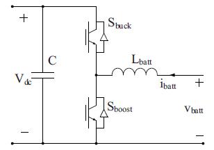
DCfastchargingstationconfigurationincludesEVbatteries,on boardcharger,grid connectedinverter,dcbus,LCLfilterand step up transformer.It implements V2G G2V framework in microgrid. There are twoimportant components of this charging stationare
a) Batterycharger
b)Grid connectedinverterandLCLfilter
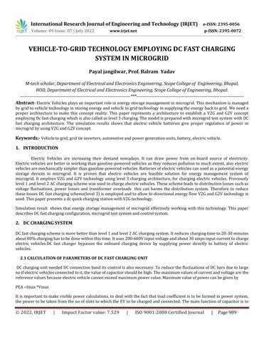
Fig2:batterychargerconfiguration
Fig1:EVchargingsystemforDCfastchargingstation
a) Battery charger configuration
DCchargersforDcfastchargingsystem aresituatedoff boardndembeddedinaEVSE.Theimportantcomponentof an off board charger employing V2Gfunctionality is bidirectional dc dc converter. Bidirectional DC DC converter are judged by current and voltage supply from one side. “The current in double sided transducers must be travelled in both sides. As we know there is a no power key this way, the one way key MOSFET or IGBT are placed parallel in battery charger circuit. Battery chargers are acts as power converters. These charges can be used in three different waysbuck,boostandbuck boostconverters.TwoIGBTswitchusedfortwodifferentvalues
1) Buck mode operation: It is a charging mode, where power flows from grid to vehicle. In this mode when upper switch is operating ;Iehaving low valueconverteract asa buck converter andsyeps down the ‘input voltage(Vdc) to battery charging voltage( Vbatt). When switch is off, through inductor and diode of lower switchcurrentcompletesitsreturnpath.
Vbatt =Vdc*D
Disthedutyratioofupperswitch
2) Boostmodeoperation: theconverterisactasboostconverterwhenlowerswitchiscooperating.Itstepsup the battery voltage (Vbatt) to DC bus voltage (Vdc). When the switch is in on state through an inductor, current continues to flow and completes its path through anti parallel diode of upper switch and the capacitor.Itisadischargemode.Inthiscasepowerflowsfromvehicletogrid.Outputvoltageinboostmode isgivenby
International Research Journal of Engineering and Technology (IRJET) e ISSN: 2395 0056
Volume: 09 Issue: 07 | July 2022 www.irjet.net p ISSN: 2395 0072
Vdc=Vbatt/1 D’ WhereD’isdutyratiooflowerswitch.
b) Grid connected inverter and LCL filter
ThethreephasegridconnectedinverterisusedtoconvertACpowerintoDCpowerandalsopermitsthereverseflow of current through anti parallel diodes of the switches. Double sided power flow has to be flow using six pulse inverter.Morethenumberofpulses,lessthecurrentfluctuations.Therearetwotypesoffilteractivefilterandpassive filter. Inthis system weare using passive filteras they interface withsystem and reduceharmonics.Inductor filters are first order filter and required large of inductor to reduce harmonics but this leads to voltage drop. LC filter is secondorderfilter.Byusing thisfilterinrushcurrent andoutputcapacitorproblemsarrives. ThereforeLCL filteris usedinthissystemwhichreducesharmonicsandobtained puresinusoidalvoltageandcurrent.Themainadvantage ofusingthisfilterithastwo inductorthereforesystemremainsinsteadystate.
3.CONTROL SYSTEM
a) Off board charger control
Forcharging/dischargingcontrolofbatterycharger,currentcontrol strategyusingPIcontrollersisused.Referencebattery current get compared with zero, to determine polarity of current wave. This is to be done to decide whether it is charging modeordischargingmode.Whenanyonemodeisgetselectedthenreferencecurrentiscomparedwithmeasurementcurrent to find error. This error is passed through PI controller, this generates pulse for Sbuck/ Sboost, It is noted that “ Sbuck will turnedoffinchargingmodeandSboostwillturnedoffindischargingmode”.
b) Inverter control
Insynchronismwithreferenceframeacascadecontrolisprovidedforinvertercontroller.Controllerstructureismadeupof twooutervoltagecontrolloopandtwoinnercurrentcontrolloops.D axisouterloophascontroloverdcbusvoltageandinner loop has control on active AC current. Also, q axis outer loop controls AC voltage and q axis inner loop regulates reactive current.
4. MICROGRID TEST SYSTEM CONFIGURATION
In this test system A 100KW wind turbine and 50 KW solar PV array act as generation sources. EV battery storage system included4EVbatterieswhichareconnectedto1.5KVdcbusofchargingstation. Aboostconverterhasmaximumpowerpoint tracking controller, to this boost converter a solar PV is connected. Distribution feeder of 25KV and equivalent transmission system are included in utility grid. At common coupling point(PCC) a wind turbine is connected to microgrid, this turbine is driven by doubly fed induction generator. Function of transformer connected is to step up the voltages and connect the respectiveacsystemstoutilitygrid.
5. SIMULATION RESULTS
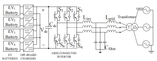
ThedesigningandmodulationofDCfastchargingsystemforelectricvehicleinmicrogrid issuccessfullyandtheresultsshows that it works precisely. Wind turbine is work preferably at rated speed giving maximum power up to 100KW. Solar photovoltaicsystemischeckedunderstandardconditionsitcanprovidesmaximumoutputpowerof50KW.Toworkatunity powerfactor,the480VACbusisconnectedto150KWresistanceload.AccordingtoreferenceofCGIreactivecurrentissetto zero.Itisproventhat“theinitialstateofchargeofelectricvehicleissetto50%andoncethesteadyconditionsareobtained V2G and G2V power transfer is carried out using batteries of EV1 and EV2”. Table 1 shows current set points for battery chargingcircuitsofEV1andEV2.Fig3and4shows batteryparameterswhenEV!IsoperatinginV2GandEV2isoperatingin G2Vmodes.
International Research Journal of Engineering and Technology (IRJET) e ISSN: 2395 0056
Volume: 09 Issue: 07 | July 2022 www.irjet.net p ISSN: 2395 0072
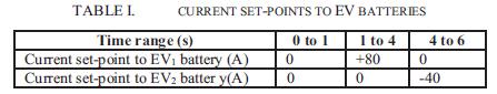
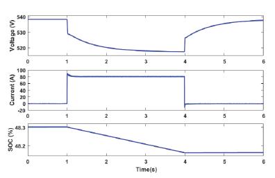
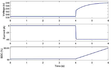
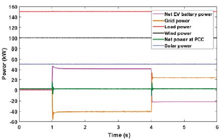
Fig3:voltage,currentandSOCofEV1duringV2Goperation fig4:voltage,currentandSOCofEV2duringG2Voperation
Active power profile of various components in the system is shown in fig 5. The power from grid changes to adapt power transfer by electric vehicles. “ the negative polarity of grid from 1s to 4 shows power transferred from vehicle to grid”. The changeinpolarityat
4sshows power is transferred by grid to charge the vehicle.Thisshowsthe V2G G2Voperation. Net power PCCiszero, this showsthatpowerisbalancedinthesystem.
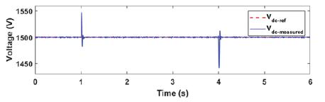
Fig5:Activepowerprofileofvariouscomponentsinthesystem fig6:dcbusvoltageregulation
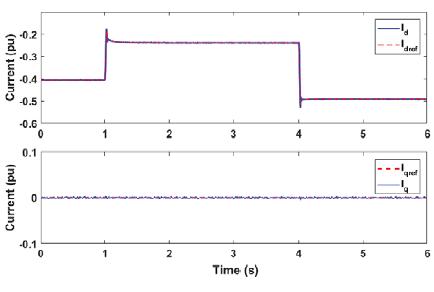
Fig6showstheregulationofDcbusvoltagebyoutervoltagecontrolloopofinverterat1500V. Referencecurrenttracking by
innercontrolloopisshowninfig7.
International Research Journal of Engineering and Technology (IRJET) e ISSN: 2395 0056
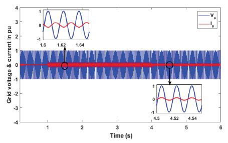
Fig7:referencecurrenttrackingtrackingby fig8:gridvoltage¤tduringV2G-G2Voperationinverter
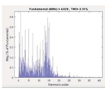
Theharmonicdistortionanalysisiscompletedongridijectedcurrentandtheresultisshowninfig9.AssaidinIEEEstd1547 “harmoniccurrentdistortiononpowersystems69KVandbelow arelimitedto5%THD.TheTHdofgridinjectedcurrentis obtainedas2.31%andcarriedoutbyLCLfilter”.
Fig9:harmonicspectrumanTHDofgridinjectedcurrent
6. CONCLUSION
Architecture of Dc fast charging in microgrid is presented in this paper. DC system with off board chargers and inverter is designed to connect the EVs to microgrid. Control system is designed to allow bidirectional energy flow. Simulation results shows the smoot power flow between EVs ad microgrid. In this work active power regulation in microgrid has been consideredandV2Gsystemcanbeusedforreactivepowercontrol&frequencyregulation.
REFERENCES
[1]C.Shumei,L.Xiaofei,T.Dewen,Z.Qianfan,andS.Liwei,“TheconstructionandsimulationofV2Gsysteminmicro grid,”in ProceedingsoftheInternationalConferenceonElectricalMachinesandSystems,ICEMS2011,2011,pp.1 4.
[2]S.Han,S.Han,andK.Sezaki,“Developmentofanoptimalvehicle togridaggregatorforfrequencyregulation,”IEEETrans. SmartGrid,vol.1,no.1,pp.65 72,2010.
[3] M. C. Kisacikoglu, M. Kesler, and L. M. Tolbert, “Single phase on board bidirectional PEV charger for V2G reactive power operation,”IEEETrans.SmartGrid,vol.6,no.2,pp.767 775,2015.
Volume: 09 Issue: 07 | July 2022 www.irjet.net p ISSN: 2395 0072 © 2022, IRJET | Impact Factor value: 7.529 | ISO 9001:2008 Certified Journal | Page993
International Research Journal of Engineering and Technology (IRJET) e ISSN: 2395 0056 Volume: 09 Issue: 07 | July 2022 www.irjet.net p ISSN: 2395 0072
[4] A. Arancibia and K. Strunz, “Modeling of an electric vehicle charging station for fast DC charging,” in Proceedings of the IEEEInternationalElectricVehicleConference(IEVC),2012,pp.1 6.
[5] K. M. Tan, V. K. Ramachandaramurthy, and J. Y. Yong, “Bidirectional battery charger for electric vehicle,” in 2014 IEEE InnovativeSmartGridTechnologies Asia,ISGTASIA2014,2014,pp.406 411
[6]joaoc.Ferreira,Vitormonteriro,joaol.Alfonso,Albertosilva,“smartelectricVehicleDesign”conferencepaperIEEE,June 2011,758 763,Germany.
[7]AykutFatihGUVEN,SalihBurakAKBASAK,“DCfastchargingstationmodelingandcontrolofelecrtricvehicles”,Karadeniz FenBilimleriDergisitheblackseajournalofscience,Dec2021,680 704,Yalova,Turkey.
[8]clement NYnsKhaesenE.andDriesenJ,”theimpactofchargingplug in hybridelectricvehiclesoaresidentialdistribution grid”,tanspowersystem25(1),2010,371 388.
[9]Seshasaibagdi,A.Apparao,VenkateshwaraRaoK.M.,“VehicletogridtechnologyemployingDcfastchargingconfiguration inmicrogridusingFuzzycontrollers”,JUNikhyat,volume11,Jan2021,752 760Srikakulam,Vizianagaram,India.
[10] Femina Mohhamad Shaeel, OM P. Malik, “ Vehicle to grid technology in microgrid using Dc fast charging architecture” IEEECanadianconferenceofelectricalandcomputerengineering,2019,1 4,Calgary,Canada.