International Research Journal of Engineering and Technology (IRJET) e ISSN: 2395 0056

Volume: 09 Issue: 07 | July 2022 www.irjet.net p ISSN: 2395 0072
International Research Journal of Engineering and Technology (IRJET) e ISSN: 2395 0056
Volume: 09 Issue: 07 | July 2022 www.irjet.net p ISSN: 2395 0072
1PG Student, UVCE, Bengaluru, 2Assistant professor, RRCE, Bengaluru, 3Professor, Dept. of civil Engineering, UVCE, Bengaluru. ***
Abstract Different plastic hinge length are considered to be effective parameter in the user defined hinge properties. Inthis study the possible differences in the results ofpushover analysis due to default and user defined hinge length using various hinge length formulation available in literature by considering G+7 storied RC structures which is modeled in SAP 2000. In present study is done assigning user defined hinges for beams and columns we given calculated moment curvature relations as input I account new plastic hinge length formula for this study. Base shear and displacement capacity of the structures for new formula are similar to various plastic hinge length formula’s. The uncertainties in plastic hinge length does not effect on the performance of the building. The observations clearly show that the user defined hinge model is better than the default hinge model in reflecting nonlinear behavior compatible with the element properties. However, if the default hinge model is preferred due to simplicity, the user should be aware of what is provided in the program andshould avoid the misuse of default hinge properties.
Key words: Performance based design, pushover analysis, Moment curvature analysis, plastic hinge length.
In Earthquake Engineering research area, which has been significantly improved especially in the last 40 50 years, recentresearcheshavebeensignificantlyconcentratedonthe ideaof“performance basedearthquakeengineering(PBEE)”. Performance baseddesignandassessmentapproacheshave gainedmorepopularity.ThemainobjectiveofthePBEEisto answer the question of “what would be the performance (dynamic response and resulting damage) of a structure duringthe“expectedearthquakes”atthesite?”Performance based methods require reasonably accurate estimates of inelasticdeformationandresultingstructuraldamage.
Therapidgrowthoftheurbanpopulationandtheconsequent pressureonlimitedspacehaveconsiderablyinfluencedcity residentialdevelopment.Thehighcostofland,desiretoavoid a continuous urban sprawl, and the need to preserve important agricultural production have all contributed to drive residential buildings upward. Because of the local topographicalrestrictions,tallbuildingsaretheonlyfeasible solutionssometimesforhousingneeds. Theprobabilityand
interestofhighrisestructureshavealwaysdependentonthe availablematerials,thelevelofconstructiontechnologyand thestateofdevelopmentofservicesnecessaryfortheuseof thebuilding.Asaresultsignificantadvanceshaveoccurred from time to time with the advent of a new material, constructionfacilityorformofservice.
Plastic hinges form at the maximum moment region of reinforcedconcretesections.Thedeterminationoftheplastic hingelengthisacriticalstepinpredictingthelateralload drift responseofcolumns. Asitisdifficulttoestimatetheplastic hingelengthbyusingsophisticatedcomputerprograms,itis often estimated based on experimental data or by using empiricalequations. However,severalfactorsinfluencethe length of plastic hinge, such as: a) level of axial load; b) moment gradient;c) the value of shearstress in the plastic hinge region; d) the amount and mechanical properties of longitudinal and transverse reinforcement; e) strength of concrete;ande)levelofconfinementprovidedinthepotential plastic hinge zone. The simplified equations available in literaturedo not contain all or most of the aforementioned factors.
Thepresentstudyaimsto evaluatetheperformanceofthe TallRCbuildingconsideringthevariousplastichingelength formulations.
Based on the review of literature survey, the following objectiveshavebeenaimed.
1. Develop 3D RC framed building model based on pushoveranalysisusingSAP2000.
2. To evaluate the performance of the building ConsideringUncertaintiesinthePlastichingelength.
3. To study the possible differences in the results of pushover analysis due to default and user defined hingelengthusingvarioushingelengthformulation.
International Research Journal of Engineering and Technology (IRJET) e ISSN: 2395 0056
Volume: 09 Issue: 07 | July 2022 www.irjet.net p ISSN: 2395 0072
4. To compare the inelastic behavior of the different plastichingelength.
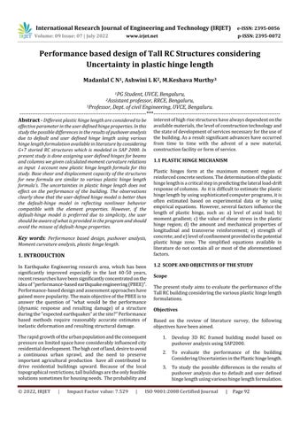
2. FLOW CHART FOR METHODOLOGY 2
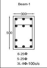
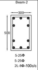
Table 1: SectionandreinforcementdetailsofBeam
Beam Dime nsion (mm)
Top Reinforc ement
Bottom Reinforcem ent
Transverse Reinforceme nt
B 1(0 5storey) 300x 500 6 25ϕ 5 25ϕ 3L 8ϕ @ 100C/C
B 2(6 8) 300x 500 5 25ϕ 5 25ϕ 2L 8ϕ @ 100C/C
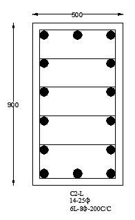
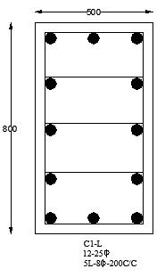
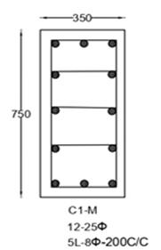
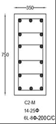
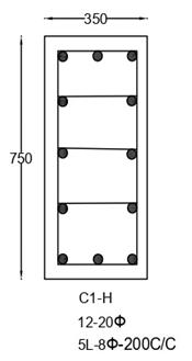
Table 2: SectionandreinforcementdetailsofColumn
Column Type Dimensi on
Main Reinforcement Transverse Reinforcement
C1 L(0 2) 500X800 12 25ϕ 5L 8ϕ@200C/C
C1 M(3 5) 350X750 12 25ϕ 5L 8ϕ@200C/C
C1 H(6 8) 350X750 12 20ϕ 5L 8ϕ@200C/C
C2 L(0 2) 500X900 14 25ϕ 6L 8ϕ@200C/C
C2 M(3 5) 350X750 14 25ϕ 6L 8ϕ@200C/C
C2 H(6 8) 350X750 14 20ϕ 6L 8ϕ@200C/C
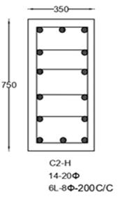
Fig 1:FlowchartforMethodology
Performancebaseddesignusingnonlinearpushoveranalysis involves tedious and intensive computational effort, is a iterativeprocessneededtomeetdesignerspecifiedandcode requirements.
Allbeamsare300x500mm,columnsdimensionsofground storey and first storey of C1 is 500x800mm, C2 is 500x900mmandfrom2ndstoreyto8thstoreythecolumn dimension350x750mm.ThegradeoftheconcreteisM26and steelisFe500.
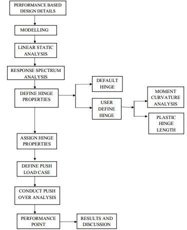
Fig -2:performancebased designdetails
International Research Journal of Engineering and Technology (IRJET) e ISSN: 2395 0056
Volume: 09 Issue: 07 | July 2022 www.irjet.net p ISSN: 2395 0072
Moment curvature analysis is a method to accurately determine the load deformation behaviour of a concrete sectionusingnonlinearmaterialstress strainrelationship.It is the representation of strength and deformation of the sectionintermsofmomentandcorrespondingcurvatureof the section. The relationship between the moment and curvature of reinforced concrete sections is an important parameter for carrying out pushover analysis considering user defined hinge length. These moment curvature data obtainedfromMicrosoftexceloffice.
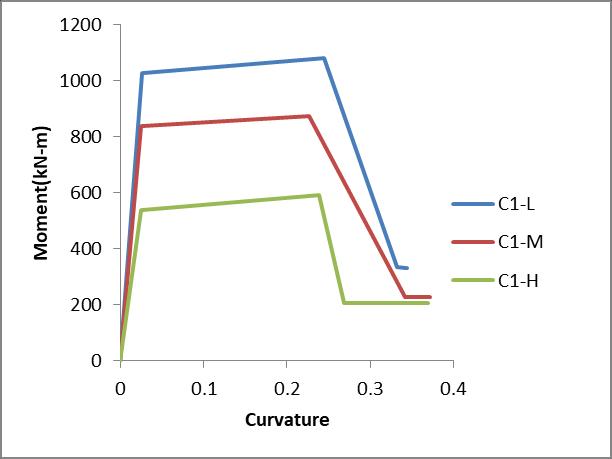
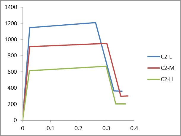
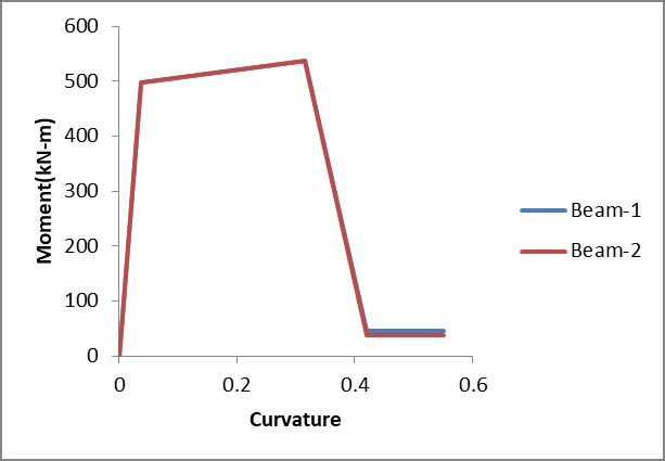
Chart -2:Momentcurvaturerelationshipforcolumns
Various empirical expressions have been proposed by investigatorsfortheequivalentlengthofplastichingeLp.
1.Corley’sformula(parkandpauley1975,corley1966) Lp=0.5d+0.2√d(z/d)
2.Sawyer’sformula(parkandpauley1975,sawyer 1964) Lp=0.25d+0.075z
Chart 1:Momentcurvaturerelationshipforbeams
3.Pauley Priestleyformula[pauley&Priestley1992] Lp=0.08z+0.022dbfy
4.Mattock’sformula(parkandpauley1975,mattock 1967) Lp=0.5d+0.05z Where,z=distanceofcriticalsectionfrompointof contraflexure d=effectivedepthofthemember db=diameterofmainreinforcingbars
Basedontheliteratureaboveplastichingelengthformulas areused.ButresearchpurposeIaccount newsimpleformof plastichingelengthequation.
Lp=0.25H
Where,Histhesectiondepth
The objective of this study is to see the variation of load displacementgraphandcheckthemaximumbaseshearand displacement of the frame. From nonlinear static pushover analysis conducted, base shear v/s roof displacement was obtained from SAP2000. The resulting base shear and roof displacement obtained considering uncertainties in plastic hingelength
© 2022, IRJET | Impact Factor value: 7.529 | ISO 9001:2008 Certified Journal | Page94
International Research Journal of Engineering and Technology (IRJET) e ISSN: 2395 0056
Volume: 09 Issue: 07 | July 2022 www.irjet.net p ISSN: 2395 0072
plastic hinge length formulation: the variation in the performanceofthestructuresislessthan5%.
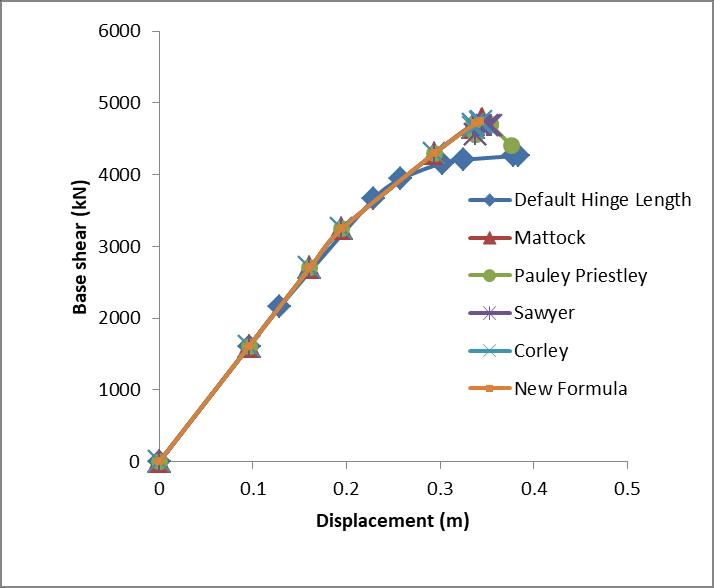
Table 3.3:performancepoint (xdirection)fordifferent plastichingelength
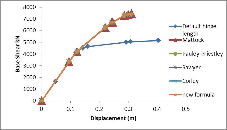
Chart 3:pushovercurve(xdirection)fordifferentplastic hingelength
Chart -4:pushovercurve(ydirection)fordifferentplastic hingelength
Themaximumbaseshearofthestructureintheuserdefined hingemodelisgreaterthanthedefaulthingemodelinbothX andYdirections.Maximumroofdisplacementofthebuilding inthedefaulthingemodelisgreaterthanuserdefinedhinge model inbothXandYdirections.
The seismic performance of building is evaluated using capacity spectrum method (CSM). The intersection pointof capacityspectrumanddemandspectrumsuchthatcapacity equals demand is performance point.. Tables 3.3 and 3.4 displaysperformancepointofthestructureforanearthquake inXandYdirectionrespectivelyintermsofbaseshear,roof displacementfromFEMA356andspectralaccelerationand spectraldisplacementobtainedfromATC40
The performance of the building (base shear and displacement capacity) are similar in various user defined
Base shear(kN) Displacement (m) Default Default 3508.62 0.219
Hinge length Plastic hinge length formulas
User defined
Mattock’s 3492.061 0.218 Pauley Priestley 3491.87 0.218 Corley’s 3491.878 0.218 Sawyer’s 3492.596 0.218 new 3492.842 0.218
Table 3.4 :performancepoint (ydirection)fordifferent plastichingelength
Hinge length Plastichinge lengthformulas Base shear(kN) Displacement (m) Default Default 4509.645 0.142
User defined
Mattock’s 4754.77 0.149 Pauley Priestley 4759.011 0.149 Corley’s 4759.025 0.149 Sawyer’s 4761.001 0.149 new 4760.526 0.149
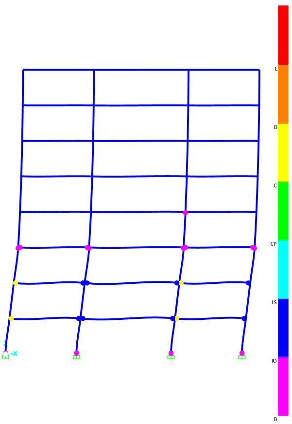
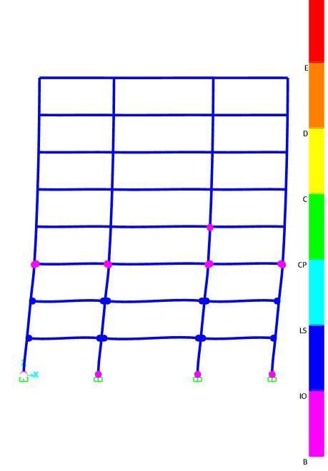
4.2.1 Hinge status at ultimate : The details of the hinges formedinthestructureinXdirectionandYdirectionisgiven intheTable6.5and6.6
International Research Journal of Engineering and Technology (IRJET) e ISSN: 2395 0056
Volume: 09 Issue: 07 | July 2022 www.irjet.net p ISSN: 2395 0072
Chart 5:performancelevelfordefaulthingelengthinY direction
Chart 6:performancelevelfordefaulthingelengthinY direction
Table 3.5: Summaryofplastichingingforpushoveranalysisatdifferentdamagelevel
Plastichinge length
Direction A B B IO IO LS LS CP CP C C D D E >E Total
Default X 418 24 16 0 0 6 0 0 464 Y 416 30 14 0 0 4 0 0 464
Table 3.6: Summaryofplastichingingforpushoveranalysisatdifferentdamagelevel
Plastichinge length
Direction A B B IO IO LS LS CP CP C C D D E >E Total
Userdefined X 424 28 12 0 0 0 0 0 464 Y 418 41 5 0 0 0 0 0 464
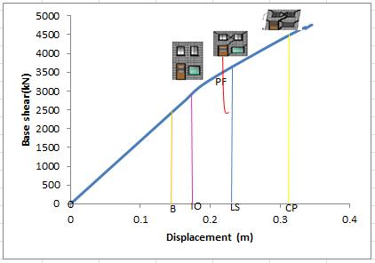
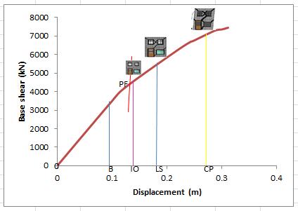
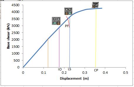
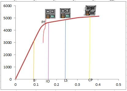
Chart 7:performancelevelforuserdefinedhingelengthin Xdirection.
Chart 8 :performancelevelforuserdefinedhingelengthin Ydirection.
International Research Journal of Engineering and Technology (IRJET) e ISSN: 2395 0056
Volume: 09 Issue: 07 | July 2022 www.irjet.net p ISSN: 2395 0072
Following are the discussion:
It was observed that, both the models, the performance level lied between Immediate occupancyandlifesafetylevelforanearthquakeinX direction.
It was observed that, both the models, the performance level lied between B and Immediate occupancylevelforanearthquakeinYdirection.
It was found that, Default hinge length, 90.1% of membersareinAtoB,5.2%ofmembersareinBto immediateoccupancy[B IO],3.5%ofmembersare inimmediateoccupancytolifesafety[IO LS]zone. Remaining1.2%ofmembersreachcollapsezoneinX direction.
It was found that, Default hinge length, 89.6% of membersareinAtoB,6.5%ofmembersareinBto IO,3%ofmembersareinIOtoLSzone.Remaining 0.86%ofmembersreachcollapsezoneinYdirection.
Damage members can be strengthen or retrofitted basedontherequirement.
Itwasfoundthat,varioususerdefinedhingelength, 91.3%ofmembersareinAtoB,6.2%ofmembers are in B to immediate occupancy [B IO], 3.5% of membersareinimmediateoccupancytolifesafety [IO LS]zoneinXdirection.
Itwasfoundthat,varioususerdefinedhingelength, 90%ofmembersareinAtoB,9%ofmembersarein B to IO, 1% of members are in IO to LS zone in Y direction.
Itwasfoundthatnoneofthemembersreachcollapse zone for user defined hingemodel in both X and Y direction. Hence the building poses some residual strength.
The present building model is safe for minor earthquakes
Thefollowingconclusionswereobserved:
Performance of the building increases when the sectionalsizeofcolumnsisincreasedwhilekeeping samereinforcement.
The uncertainty in plastic hinge length does not effect on the performance of the building. The performance of the building (base shear and displacementcapacity)aresimilarindifferentplastic hingelength:thevariationintheperformanceofthe structuresislessthan5%.
The differences inDefaulthingesanduser defined hinges for various plastic hinge length has considerableeffectsonthemaximumbaseshearand displacementcapacityofthestructures;thevariation inthebaseshearanddisplacementcapacityis 10% inXdirectionand30%inYdirection.
International Research Journal of Engineering and Technology (IRJET) e ISSN: 2395 0056
Volume: 09 Issue: 07 | July 2022 www.irjet.net p ISSN: 2395 0072
ThestiffnessofstructureintheYdirectionismore thanthatinXdirection.Thatisparticularlydueto orientationofcolumnsalongYaxis.
Comparison of hinging pattern indicates that both models with default hinges and the various user defined hinges estimate plastic hinge formation at theultimatestatetherearesignificantdifferencesin thehingingpatterns.
[4] Biradar,S.H.(2015,August)3DRCMultistoreyBuilding SeismicAssessmentwithUserDefinedHinges.
[5] Sonwane, D. P., & Ladhane, K. B. (2015). Seismic performance based design of reinforced concrete buildings using nonlinear pushover analysis.InternationalJournalofEngineeringResearch andTechnology,4(06).
Mostofthehingesdevelopedinthebeamsandfew in the columns of both models it indicates strong columnandweakbeam.
[6] Subramanian, N. (2009). Plastic Hinge Length of ReinforcedConcreteColumns.PaperbySungjinBaeand OguzhanBayrak.ACIStructuralJournal,106(2),233.
Thisstudyiscarriedouttoinvestigatethepossible differences between pushover analyses of the default hinge and user defined hinge models. The observations clearly show that the user defined hingemodelisbetterthanthedefault hingemodel becausedamageislimited. However,ifthedefault hingemodelispreferredduetosimplicity,theuser shouldbeawareofwhatisprovidedintheprogram and should definitely avoid the misuse of default hingeproperties.
This study focuses on Non linear Static Analysis proceduretochecktheperformanceofthestructure. But,thestudycanbeextendedtoNon LinearTime HistoryAnalysisandtheresultscanbecheckedfor moreaccuracy.
[7] Ashraf Habibullah, S. E., & Stephen Pyle, S. E. (1998). Practical three dimensional nonlinear static pushover analysis.Structuremagazine,winter
[8] Bento, R., Falcao, S., & Rodrigues, F. (2004, August). Nonlinear static procedures in performance based seismic design. InProceedings of the 13th world conference on earthquake engineering, Vancouver, Canada
In this study pushover analysis was carried out. Further studies compare the results with experimentalobservations.
Tostudythedifferencesinresultsofvariousplastic hingelengthfordifferentstoreyheight
[1] Inel,M., & Ozmen,H. B.(2006).Effectsof plastichinge propertiesin nonlinearanalysisofreinforcedconcrete buildings.Engineeringstructures,28(11),1494 1502.
[2] Hede, N. P., & Babunarayan, K. S. (2013, November). Effectofvariationofplastichingelengthontheresultsof non linearanalysis.InInternationalJournalofResearch in Engineering and Technology (IJRET), IC RICE ConferenceIssue(pp.2319 1163).
[3] CM, R. K., Choudhary, V., Narayan, K. S., & Reddy, D. V. (2014).MomentCurvatureCharacteristicsforStructural ElementsofRCBuilding.