International Research Journal of Engineering and Technology (IRJET) e ISSN: 2395 0056

Volume: 09 Issue: 07 | July 2022 www.irjet.net p ISSN: 2395 0072
International Research Journal of Engineering and Technology (IRJET) e ISSN: 2395 0056
Volume: 09 Issue: 07 | July 2022 www.irjet.net p ISSN: 2395 0072
Abstract Endmillingisanoperationwhichemploysanend millcutterforfacemilling,edgemillingandslotmilling.Itis averywidelyusedmachiningoperationthatisextensively used in shipyard, automotive & aerospace industries. Different types of tool paths can be used during the end milling of the AISI D3 material. Each toolpath has its own effects on the performance characteristics of slot milling. Sometoolpathsmayprovidebettersurfaceroughnesswhile other toolpaths may provide lower cutting force. The manufacturerwantstoproducethemachiningcomponents withbettersurfacefinish.Atthesametimethemanufacturer wantslowercuttingforceandlessamountofenergytobe spent while machining the components. Hence, it is important to determine the best toolpath and cutting conditions which will provide lower surface roughness of themmachinedcomponent,lowercuttingforceonthetool and less amount of energy spent for the machining. This research result would identify the best toolpath and optimum cutting parameter which will provide better surfacefinishaswellaslowcuttingforceandspecificcutting energy.
Key Words: AISI, End Milling, Cutting Force, Toolpath, SurfaceFinish
There has been an increasing demand for high quality machined components that would be highly beneficial to manufacturingindustriesasitwouldhelpthemanufacturing engineerandmechanisttoselectbestmachiningparameters andtoolpathstrategies.TheDifferenttypesoftoolpathscan beusedduringtheendmillingoftheAISID3material.Each toolpath has its own effects on the performance characteristics of slot milling. Cevdet Gologlu et.al [1] investigated the effects of cutter path strategies on the surfaceroughnessofDIN1.2738mouldsteelduringpocket milling operations based on Taguchi method. P.E Romero et.al[2]studiedtheinfluenceoftoolpathstrategyandpocket geometryonsurfaceroughness,cuttingforceandmachining time.Sometoolpathsmayprovidebettersurfaceroughness whileothertoolpathsmayprovidelowercuttingforce.The manufacturerwantstoproducethemachiningcomponents with better surface finish and at the same time want to reducecuttingforceandamountofenergytobespentwhile machining the components. Hence, it is important to determine the best toolpath and cutting conditions which
***
will provide lower surface roughness of the machined component,lowercuttingforceonthetoolandlessamount ofenergyspentforthemachining.
The experimental runs were generated using L9 Taguchi orthogonal array. The input parameters selected are Tool path, Cutting speed and feed rate. Depth of cut remains constant during the experiment. Jayakrishnan et.al [3] Taguchi Greyrelationalanalysiswasutilizedtooptimizethe multi response end milling characteristics during the end milling of Aluminum alloy. B. Rajeswari et.al [4] used response surface methodology to generate the design of experimentandthenutilizedthegreyrelationalanalysisto findtheoptimummachiningcharacteristics.MastercamX6 software was used to generate the NC codes for the experimental runs required for the machining of the components.UsingtheNCcodesobtainedfromMastercam software the experiments were performed in the 3 axis verticalmillingmachine.Theperformancecharacteristicsof themachinedcomponentsweremeasured.Theoptimization oftheparameterswasdoneusingGreyrelationalanalysis. The optimum cutting conditions were obtained from the result which was compared with the initial cutting parameters to verify whether the performance characteristicsofthemachinedcomponentswereimproved ornot.
Thus,theresultofthisresearchwillhelpthemanufacturer to select the best toolpath strategy and cutting conditions whichwillhelphimtomanufacturehighqualitycomponents andsimultaneouslyreducingthecostofproduction.
Objectiveofthisresearchare:
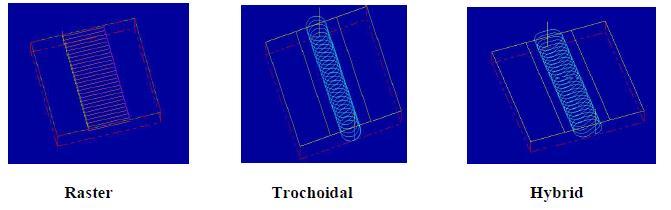
1. To study the influence of tool path (Raster, Trochoidal and Hybrid) with respect to output qualitycharacteristics
2. Toanalysisthesignificanceofprocessparameters (speed,feedrate)alongwithtoolpathwithrespect tooutputqualitycharacteristics.
3. To optimize the process parameters by utilizing GreyRelationalAnalysis.
International Research Journal of Engineering and Technology (IRJET) e ISSN: 2395 0056
Volume: 09 Issue: 07 | July 2022 www.irjet.net p ISSN: 2395 0072
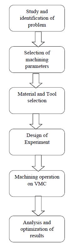
Materialused:AISID3STEEL
AISIstandsforAmericanIronandSteel Institute.D3steel has a high percentage of chromium and carbon in its composition which helps the material to provide dimensional stability, wear resistance and resistance to deformationundercompressiveforces.CompositionofAISI D3materialcanbeclearlyseeninFig.1
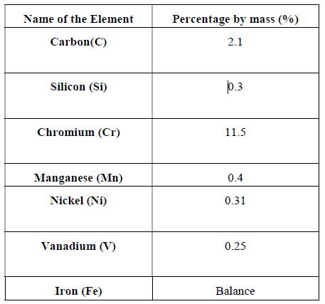
Carbide tool materials (Fig.2) was used as cutting tool material which includes carbides of silicon, titanium, tungsten as well as other compounds of a metal. Carbide toolsareusedinmachiningvariousgradesofsteelmaterials. The milling experiments are to be conducted on the VMC machine,hencecuttinginsertsarepreferred.Theinserttobe usedformillingoperationisR390 11T308M PM1030
(SANDVIK) with a tool nose radius of 0.8 mm and coated withTiAl(N)byphysicalvapordeposition.
2.1.
Fig.1 CompositionofAISID3Material
Fig.2 PVDCoatedCarbideMaterial
Selection of input parameters depends on the work piece andthecuttingtool.Inthisresearch,fourinputparameters areused:
1.Toolpath
2.CuttingSpeed(m/min)
3.FeedRate(mm/tooth)
CuttingdepthistheconstantparameterwhileCuttingSpeed, Feed rate and toolpath are the controllable cutting parameterstobeusedintheexperiments.Thecontrollable parameters are set into three levels as per the literature survey. As per the specifications of the work piece and cuttingtool,thecuttingspeedhasarangefrom40m/minto 80m/min,thefeedratehasarangefrom0.05mm/min to 0.15mm/minandtoolpathsusedareRaster,Trochoidaland Hybrid. Table 3.2 shows the input parameters. Tool path Trochoidal,DOC 1mm
Feed Path (mm/tooth)
Table 2.1: ProcessParametersandtheirlevels
International Research Journal of Engineering and Technology (IRJET)
e ISSN: 2395 0056
Volume: 09 Issue: 07 | July 2022 www.irjet.net p ISSN: 2395 0072
To optimize these parameters and levels, Taguchi L9 orthogonal array is used. Based on this tabulation, experimentsaregoingtobeperformed.Table2.2showsthe designofexperimentswhichweregeneratedusingTaguchi L9arrayfor3parametersand3leveldesign
Ex. No Toolpath CuttingSpeed (m/min) Feed Rate (mm/tooth)
1 Raster 40 0.05
2 Raster 60 0.1
3 Raster 80 0.15
4 Trochoidal 40 0.1
5 Trochoidal 60 0.15
6 Trochoidal 80 0.05 7 Hybrid 40 0.15 8 Hybrid 60 0.05 9 Hybrid 80 0.1
Table 2.2: DesignofExperiments
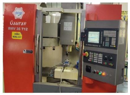
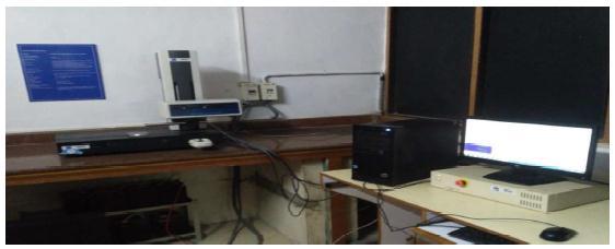
Initially,the3Dsimulationoftheworkpieceisdonebyusing MASTERCAMX 6software.TheNCcodesaregeneratedwith helpofthissoftware.Trochoidaltoolpathstrategy is used. The NC codes which were obtained from the softwareareuploadedonCNC828DSiemensVMCMachine. Thentheexperimentsareconductedonthemachine(Fig.3).
3. Model Gaurav BMV35T12 4. CNCController Siemens Sinumerik828Dbasic 5. Spindlespeedmaximum 8000RPM
Mastercam X6 software is used to conduct the simulation andNCcodeweregenerated.
Thefigure4showsthesamplesimulationmodel.
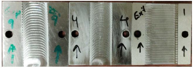
Toavoidrustingonthemachinesurfaceoilisappliedonthe workpiece after completion of all experiments. Figure 5 showsthemachinedworkpieces.Thefirstworkpieceshows the Hybrid toolpath used in 9th experiment. The second workpiece shows the Trochoidal toolpath from the 4th experiment.ThethirdworkpieceshowstheRaster/One way toolpathfrom the1stexperiments.The experimentswere performed on both the sides of the AISI D3 material to reduceamountofmaterialusedandcost.
The Surface roughness must be monitored carefully to ensuretheproductquality.Figure6showsSurfcom1400G, ACCRETECH used for measuring the surface roughness of themachinedworkpiece.Itconsistsofastyluswhichmoves over the surface to be analyzed. The stylus setup is interfaced with a computer which gives the value of the surfaceroughness.
SpecificationsoftheVMC: 1. MachineName 3AxisVMC 2. Make BFW
International Research Journal of Engineering and Technology (IRJET) e ISSN: 2395 0056
Volume: 09 Issue: 07 | July 2022 www.irjet.net p ISSN: 2395 0072
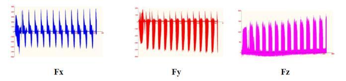
Thecuttingforcesobtainedforhybridtoolpathwereshown infig.10
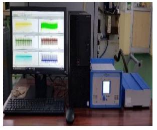
CuttingforceismeasuredwiththehelpofKISTLERmulti componentdynamometer.
The dynamometer and the acquired results are shown figure.7
Thecuttingforcesobtainedfromalltheexperimentswere tabulatedintable3.1
Exp. No Fx (N) Fy(N) Fz(N) F(N)
1 423 125 216.7 491.4396
2 520 420.8 177 691.9549
3 635.7 563 233.8 880.7644
4 592 228.3 235 676.6165
5 629 273.1 324.1 758.4625
6 361 143.4 148.9 415.9997
7 781.9 264 250 862.3013
8 453.2 191.7 156.3 516.303
9 634 231.7 238 715.7408
WhereFx,Fy,Fzdenotetangential,radial,andaxialcutting forces (N) which are obtained from the Dyno ware setup. The cutting forces obtained for raster toolpath (3rd experiment)wereshowninfig8
The resultant cutting force is obtained from the following formulae.
F=√Fx²+Fy²+Fz²
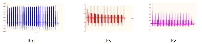
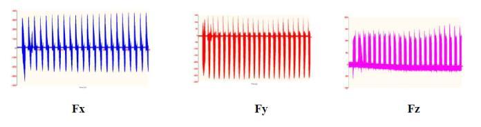
Fx=Cuttingforceintangentialdirection
Fy=cuttingforceinradialdirection
Fz=cuttingforceinaxialdirection
F=Resultantcuttingforce
The cutting forces obtained for trochoidal toolpath were showninfig.9
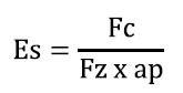
To remove a unit volume of the machined component the amount of energy exerted by the cutting tool is known as SpecificCuttingenergy.
WhereEs=Specificcuttingenergy(J/mm3)
Fc=ResultantCuttingforce(N)
Fz=Feedrate(mm/tooth)
ap=cuttingdepthinaxialdirection(mm)
International Research Journal of Engineering and Technology (IRJET) e ISSN: 2395 0056
Volume: 09 Issue: 07 | July 2022 www.irjet.net p ISSN: 2395 0072
Now all the output parameters are tabulated as shown in table3.2
Exp. No F(N) Surface Roughness (µm)
Specific Cutting Energy Es (J/mm3)
1 491.4396 0.8791 9.2637
2 691.9549 0.9693 4.3534
3 880.7644 0.4838 2.7671
4 676.6165 1.28 6.3772
5 758.4625 1.0636 3.1781
6 415.9997 0.7444 3.9208
7 862.3013 0.9622 5.4185
8 516.303 0.3399 6.4903
9 715.7408 1.0021 3.3723
Table 3.2: OutputParameters
The objectives chosen were minimizing the surface roughness, cutting force and specific cutting energy. This analysis is used to determine the optimum set of process parametersforthegivensetofexperiments.Greyrelational analysisconsistsof3stepsnamely:
1.Normalizetheobtainedoutputparametersfrom0to1.
2.Calculategreyrelationcoefficientfornormalizedoutput parameters.
3.Calculategreyrelationgradebytakingarithmeticmeanof theGRCsforeachoutputresponseinasingleexperiment.
4. The GRGs are then ranked in descending order and the experiment with the highest value of GRG is the optimum experiment
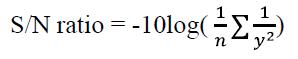
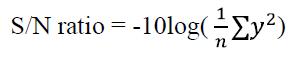
The signal to noise ratio (S/N ratio), where the desirable outputisrepresentedbysignalandundesirablevariationis represented by noise, is used to evaluate the quality characteristics of a control variable. The S/N ratio can be evaluated using two cases, ‘’Smaller the better’’ & ‘’Larger thebetter”.Assurfaceroughness,CuttingForceandSpecific Cuttingenergymustbeminimized,thisstudyutilizesonly thesmallerthebettercase.
ThesmallerthebetterS/Nratioequationisgivenby:
ThelargerthebetterS/Nratioequationisgivenby:
TheS/Nratioswerecalculatedforeachoutputcharacteristic andweretabulatedintable4.1
Exp. No Surface Roughnes s (Ra)
Cutting Force (Fc) Specific Cutting Energy (Es)
1 1.1192 53.8294 19.3357
2 0.2708 56.8100 12.7766
3 6.3067 58.8972 8.8405
4 2.1442 56.6069 16.0925
5 0.5356 57.5987 10.0435
6 2.5639 52.3819 11.8676
7 0.3347 58.7138 14.6776
8 9.3730 54.2581 16.2453
9 0.0182 57.0935 10.5586
Table 4 1: S/NRatios
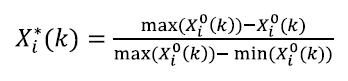
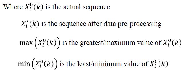
Asperrequiredprocedurenormalizationistobedonefor the output parameters. For calculating normalized values, thefollowingequationsareused.
Sincealltheoutputparameterscomesunderthecategoryof ‘Smaller the better’ , we have used above mentioned equationwhere,
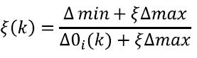
TheGRCcanbecalculatedas:
2022, IRJET | Impact Factor value: 7.529 | ISO 9001:2008 Certified Journal
International Research Journal of Engineering and Technology (IRJET)
e ISSN: 2395 0056
Theweightageforroughnessistakenas0.4andforcutting forceandspecificcuttingenergyistakenas0.3respectively.
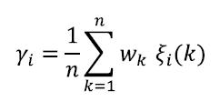
Whereas Grey relation grade is calculated by taking arithmeticmeanoftheGRCsforeachoutputresponseina singleexperiment.TheGRGisdefinedas
Theaveragegreyrelationalgradeiscalculatedandfromthe table4.3,wecouldsaythatthemostinfluentialfactoramong thethreeparametersisspindlespeed.So,theidealsurface finishisobtainedbymaximizingthespindlespeedasmuch as possible. On the other hand, toolpath is the least influencingparametersbecausethedifferencebetweenthe maximumandminimumaveragegreyrelationalanalysisis minimumforthetoolpath.
Fromthetable4.2,itwasobservedthatthe6thexperiment was ranked 1 by Grey relational analysis and hence the optimum parameters are obtained as Cutting Speed 80m/min,Feedrate0.05mm/toothandtrochoidaltoolpath.
The average grey relational grade is calculated. Table 4.3 showstheaveragerelationgrade.
Exp No
Grey relational Co efficient Grey Relational Grade (GRG)
TheoptimumparameterswhichwereobtainedfromGrey RelationalAnalysiswereusedtocarryouttheconfirmation test.Theexperimentwasperformedbytakingcuttingspeed as 80m/min, feed rate as 0.05mm/min and trochoidal toolpath.Thecomparisonbetweentheoptimumparameters andtheinitialparameterswereshownintable4.4
SurfaceRoughness(µm) 0.7214
Cutting Force (Fc)
Specific Cutting Energy (Es)
Ran k Surfac e Rough ness (Ra)
1 0.3582 0.5745 0.2308 0.387837 6
2 0.3360 0.3062 0.4444 0.362231 7
3 0.6004 0.2308 1.0000 0.610389 2
4 0.2857 0.3163 0.3027 0.301581 9
5 0.3174 0.2726 0.7236 0.437829 4
6 0.4035 1.0000 0.5098 0.637801 1
7 0.3376 0.2359 0.3504 0.307965 8
8 1.0000 0.5102 0.2983 0.602858 3
9 0.3291 0.2932 0.6470 0.423092 5
Table -4.2: GRC,GRG&Rank
Input Parameters
Average Grey Relational Grade Max Min Level 1 Level 2 Level 3
Toolpath 0.4534 0.4590 0.4446 0.0056 Cutting Speed (m/min) 0.3324 0.4676 0.5570 0.2246
Feed Rate (mm/min) 0.5428 0.3623 0.4521 0.1805
Table 4.3: Average Grey Relational Grade
CuttingForce(N) 415.9098 Specific Cutting Energy (J/mm3) 3.9176
GreyRelationalGrade 0.701227
Taguchi based GRA was utilized to optimize the process parametersinendmillingoperationofAISID3steel.
1Fromtheinvestigationtheoptimumprocessparameters wereobtainedas. a)CuttingSpeed80m/min, b)Feedrate0.05mm/tooth c)trochoidaltoolpath.
2TheaverageGRAgradewascalculatedforeachparameter, and it was found that the cutting speed was the most influentialparameterfollowedbyfeedrateandtoolpath
3Trochoidaltoolpathwasfoundtobeidealtoolpathbecause the engaging time of the tool is less when compared to Raster and Hybrid. Raster and Hybrid tool path contains linearmotionwhichincreasestheengagingtimeofthetool.
4Withtheobtainedoptimumparameters,theconfirmation testwascarriedout.ThedifferenceinGreyRelationalGrade between the experiment performed with optimum parametersandthevaluesarefoundtobesurfaceroughness 0.7214μm,cuttingforce
415.9098 N, specific cutting energy 3.9176 J/mm3, Grey relationalgrade0.701227.
Volume: 09 Issue: 07 | July 2022 www.irjet.net p ISSN: 2395 0072 © 2022, IRJET | Impact Factor value: 7.529 | ISO 9001:2008 Certified Journal |
International Research Journal of Engineering and Technology (IRJET) e ISSN: 2395 0056
Volume: 09 Issue: 07 | July 2022 www.irjet.net p ISSN: 2395 0072
1. CevdetGologlu,NazimSakarya(2007).Theeffects of cutter path strategies on surface roughness of pocket milling of 1.2738 steel based on Taguchi method.Journalofmaterial
2. P.E Romero et.al [2] studied the influence of toolpathstrategyandpocketgeometryonsurface roughness,cuttingforceandmachiningtime.
3. JayakrishnanUnnikrishnanPillaietalOptimization ofmultiresponsecharacteristicsonendmillingof aluminum alloy using Taguchi Grey relational approach.MeasurementVol124,pp.291 298
4. B. Rajeswari et.al [5] used response surface methodologytogeneratethedesignofexperiment andthenutilizedthegreyrelationalanalysistofind theoptimummachiningcharacteristics.
2022, IRJET | Impact Factor value: 7.529 | ISO 9001:2008 Certified Journal