International Research Journal of Engineering and Technology (IRJET) e ISSN: 2395 0056

Volume: 09 Issue: 07 | July 2022 www.irjet.net p ISSN: 2395 0072
International Research Journal of Engineering and Technology (IRJET) e ISSN: 2395 0056
Volume: 09 Issue: 07 | July 2022 www.irjet.net p ISSN: 2395 0072
1 , Anil Rajagopal K P 2
1M.Tech student, Dept. of Production Engineering, GEC Thrissur, Kerala, India 2Assistant Professor, Dept. of Production Engineering, GEC Thrissur, kerala, India ***
Abstract The Deep drawing process is a metal forming process. In the LPG cylinder manufacturing, the upper dome and bottom dome of the LPG cylinders are making using this deep drawing process. The formability of the blanks depends on the process parameters such as clamping pressure, drawing pressure, lubrication, punch and die radii, die punch clearance, in addition to thickness of the sheet material. The one of the main loss of deep drawing is overconsumption of the raw material. in this project focus on the how to reduce the raw material consumption in the deep drawing process. The 3D geometry of the deep drawing process is drawn by using CREO software and the ANSYS software is used to conduct the analysis of the deep drawing process. Based on the analysis then suggest a suitable values for the parameters. Finally reduce the raw material consumption in the deep drawing process.
Key Words: Deep drawing, Metal forming process, Friction coefficient, blank holding pressure, CREO , Ansys workbench
The Deep drawing (DD) process is a significant metal formingprocessusedinthesheetmetalformingoperations. In the LPG cylinder manufacturing, the upper dome and bottom dome of the LPG cylinders are making using this deepdrawingprocess.Theformabilityoftheblanksdepends on the process parameters such as clamping pressure, drawingpressure,lubrication,punchanddieradii,diepunch clearance,inadditiontothicknessofthesheetmetal.
Inthedeepdrawingprocessthematerialiscutintorequired dimensions and moves to the deep drawing process. And using lubrications for the required friction condition. The scrapmaterialisusedforthemakingofprotectionring,foot ring,connectingplatesetc.Thetypesofdefects occuredin thedeepdrawingprocessarewrinkles,pitmark,lines,halve crack,lowdrawetc.
TheLPGcylindermanufacturingindustryisconcernedtheir one of the main loss is the over consumption of the raw materialinthedeepdrawingprocess.Theoverconsumption ofthematerialisduetovariationofthethicknessfromthe bottomtotopportionofthedome.Sointhisprojectselect
theparametersandfindthesuitablevaluesbyusinganalysis inthedeepdrawingprocess.
V.Sravani,M.Alekya[1],Simulationandoptimizationofdeep drawing process parameters for cylindrical cup by using FEM and taguchi. In this paper analyses the parameters usingfiniteelementanalysisandoptimalcombinationofthe parametersandtosuggestoptimalvaluesbasedonANOVA. Basedontheselectedparameterssimulatetheresults.
Chandra Pal Singh, Geeta Agnihotri [2], Finite element analysis of deep drawing process to investigate effect of friction. This research article represents deep drawing Simulationofsteelsheettoinvestigateinfluenceoffriction on product quality. In this create the 3D geometry of the model and analysis is done in the hyperworks software. Basedontheresulttaguchitechniqueisusedtoestimatethe percentageofcontributionofeachparameters.
R.Padmanabhan,M.C.Oliveira,J.L.Alves,L.F.Menezes[3], Numericalsimulationandanalysisonthedeepdrawingof LPG bottles. This paper presents a numerical simulation carriedoutandreducestheblankthinningofthedome.The major parameters selected are blank holder force and frictioncoefficient.Basedontheseparametersanalysisare carriedout.Thebestsolutionisobtainedintheapplication ofvariableblankholderforceintheanalysis
PVenkateshwarReddy,PerumallaJanakiRamulu,GSandhya Madhuri,DasariGovardhan, P VS RamPrasad[4], Design and Analysis of Deep Drawing Process on angular Deep Drawing Dies for Different Anisotropic Materials. In this papertheformabilityfordifferentmetalsheetsisobserved forangulargeometriesofdeepdrawingtools.
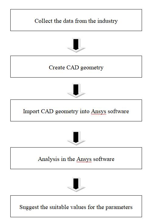
First of all collect the data from the industry. Then The geometry of the deep drawing process is drawn by using modeling software CREO. The 3D geometry imported into theansyssoftware.Fortheanalysisandsimulationprocess usingAnsyssoftware.Thensuggestthesuitablevalues for theparameters.Theresearchmethodologyusedforthework isshowninthefigurebelow.
International Research Journal of Engineering and Technology (IRJET) e ISSN: 2395 0056
Volume: 09 Issue: 07 | July 2022 www.irjet.net p ISSN: 2395 0072
Fromthesamplemeasurements,
Theminimumthicknessofthematerialis2.62,thatis not uniformlydistributingthethicknessofdome. The14.2KG cylinderneedminimum6.1KGweightand19KGcylinder needminimum7.7KGforeachhalves.Butinthecaseof14.2 kgcylinder80gramsofrawmaterialisoverconsumedeach halves production. And in the case of 19 kg cylinder 93 grams of raw material is overconsumed each halves production.
In January month 14.2 KG cylinder 29356 halves are produced and 57 rework materials are there. No rejected halvesarethere.
The overconsumption of the material= 29356×0.080 =2348.48KG
Fig 1: Researchframework
Two types of cylinders are manufacturing in the industry, thatis14.2kgcylinderand19kgcylinder.Thewidthofthe HR coil for both 14.2 kg cylinder and 19 kg cylinder are different.Butthethicknessoftherawmaterialissameand the circle cutting diameter , halve height, halve initial diameter,bungholediameter,theminimumthicknessofthe domefortheboth14.2kgcylindersand19kgcylindersare mentionedinthetablebelow.
Table 1: Measurementschecklistofthecylinders 14.2 KG CYLINDER 19 KG CYLINDER
HR COIL (IS 6240)
WIDTH 1680mm 1275mm THICKNESS 2.8 3mm 2.8 3mm
CIRCLEDIAMETER 610 614mm 673 677mm THICKNESS 2.8 3mm 2.8 3mm
HALVEHEIGHT 248 250mm 296 298mm
HALVEID 314.4 317.54 mm 330.1 333.40mm
BUNGHOLEDIA 52 52.3mm 52 52.3mm
MINIMUMTHICKNESS 2.53mmmin HPC 2.53mm min IOC,BPC 2.50mm min
The1kgrawmaterialrate(scraprate)=35Rs
Theoverconsumptionmaterialcostofthe14.2KGcylinder =2348.48×35=82196.8Rs
Inthecaseof19KGcylinder24644halvesareproducedand 45reworkshalvesarethereandnorejectedhalvesinthis month.
The over consumption of the material= 24644× 0.093 =2291.892KG
Theoverconsumptionmaterialcostofthe19KGcylinder =2291.892×35=80216.22Rs
The total cost of the overconsumption material in this month=82196.8+80216.22=162413.02Rs.
IntheAnsys softwarestatic structural analysisisselected and assign the material. Then import the geometry and model the geometry. The parameters selected are blank holder pressure and friction coefficient. The friction coefficient0.2to0.01testedandblankholderpressure11 Mpato14Mpaaretested.Twomethodsareused,constant blank holderpressure methodandvariavble blank holder pressure method.The obtained results are compared with eachother.Basedontheresultssuggestasuitablevaluesfor the selected parameters. The different stages of the deep drawingprocessintheAnsyssoftwarearegivenbelow.
International Research Journal of Engineering and Technology (IRJET) e ISSN: 2395 0056
Volume: 09 Issue: 07 | July 2022 www.irjet.net p ISSN: 2395 0072
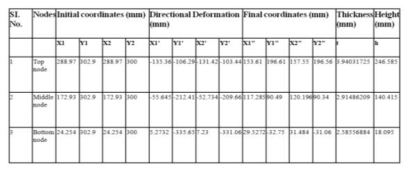
Thebestsolutionisobtainedintheblankholderpressure 12MPa and friction coefficient 0.02. The table shows the initial coordinates and directional deformation of the selectedsolution.Heretakesthetopnode,middlenode,and bottomnodeofthedome.
Table-3: Finalresultsof14.2kgcylinder
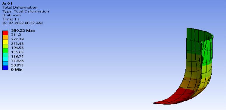
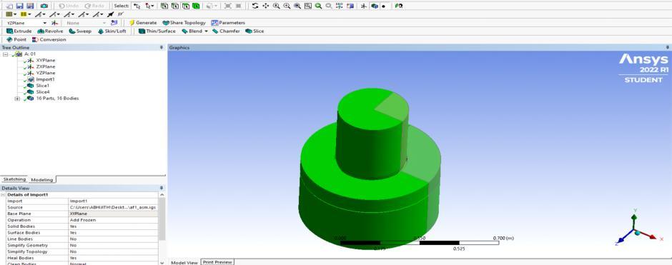
Thequarterportionofthematerialandmodelintheansys softwareandgiventhematerialassign,connections,andalso insert the displacement, fixed support, pressure, total deformation,stress,directionaldeformationsetc.Thefigure belowrepresentthetotaldeformationofthedome.
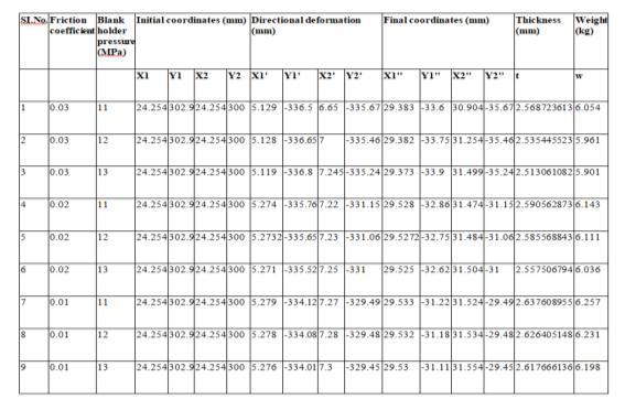
Fig-3: Thetotaldeformationofthedome
Inthecaseoftheapplicationofconstantpressureinthe14.2 kgcylinder,thefrictioncoefficienttakenfrom0.03to0.01 andtheblankholderpressuretakenfrom11Mpato13Mpa are tested. Also calculate the thickness a dome.Thetableshowsapplicationofconstantpressurein the14.2kgcylinder.
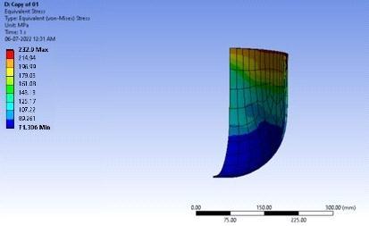
The stress distribution is varied from the top to bottom portionofthedome.Themaximumstressisobservedatthe top portion of the dome. The figure shows the stress distributionofthedome.
Table 2: Applicationofconstantpressureinthe14.2kg cylinder
Fig 4: Stressdistributionof14.2kgcylinder
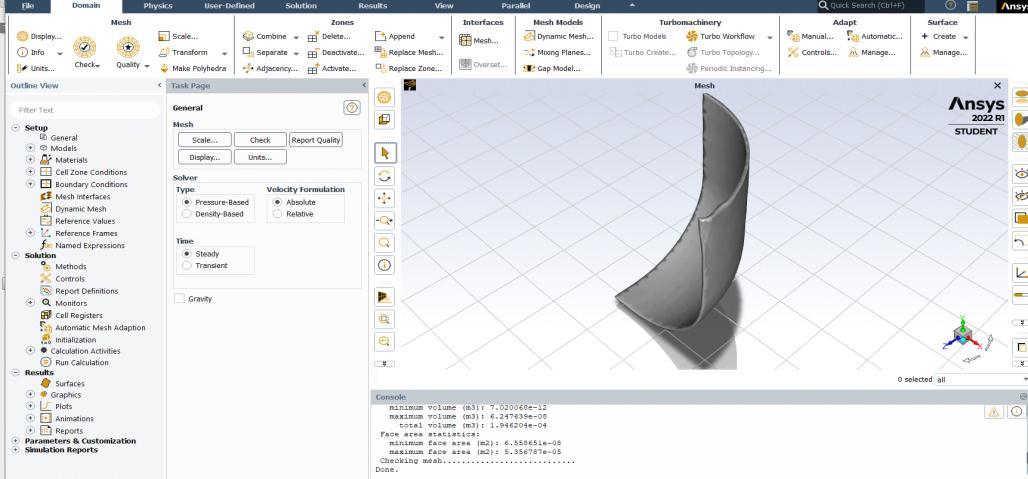
ThedomeiscutintorequiredlengthandThevolumeofthe domeiscalculatedbyusingthefluidflowfluent.Thefigure showsthevolumecalculationbyusingthefluidflowfluent.
Fig 5: Weightcalculationbyusing fluidflowfluent
International Research Journal of Engineering and Technology (IRJET) e ISSN: 2395 0056
Volume: 09 Issue: 07 | July 2022 www.irjet.net p ISSN: 2395 0072
Theweightofthedomeiscalculatedbyusingtheequation,
Inthecaseoftheapplicationofvariablepressureinthe14.2 kgcylinder,thefrictioncoefficienttakenfrom0.03to0.01 andtheblankholderpressuretakenfrom11Mpato13Mpa are tested. The only difference is applying the variable pressureastwostages.Thatisapplyingvariablepressureis devidedintoinitialstageandfinalstage.Alsocalculatethe thickness and weight of the dome. The table 6.5 shows applicationofvariablepressureinthe14.2kgcylinder.
The best solution is obtained in the initial pressure at 10 Mpaandfinalpressureat12MPaandfrictioncoefficient is 0.02.Heretakesthetopnode,middlenode,andbottomnode ofthedome.TosolvetheproblembyusingMicrosoftexcel sheet. The table below shows, the calculated final results are,
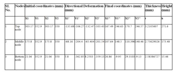
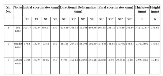
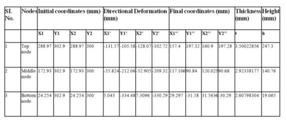
Table 4: Finalresultsof14.2kgcylinder
Similarlyinthecaseoftheapplicationofconstantpressure inthe19kgcylinder,thefrictioncoefficienttakenfrom0.03 to0.01andtheblankholderpressuretakenfrom12Mpato 14Mpaaretested.Alsocalculatethethicknessandweightof the dome. The table 6.7 shows application of constant pressureinthe19kgcylinder.
Thebestsolutionisobtainedintheblankholderpressure13 MPaandfrictioncoefficient0.02.Heretakesthetopnode, middlenode,andbottomnodeofthedome.Alsocalculate thethicknessandweightofthedome.Thetable6.8shows applicationofconstantpressureinthe19kgcylinder.
Table-5: Finalresultsof19kgcylinder
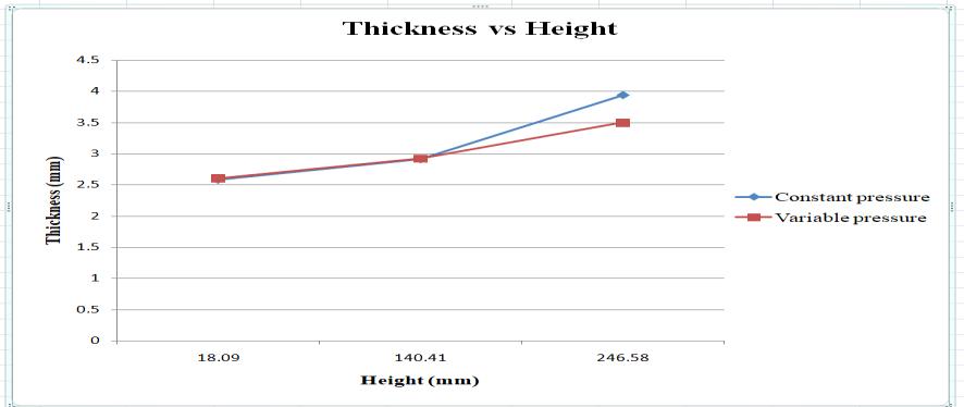
Thefigureshowsthethicknessvsheightgraphoftheboth constantpressureandvariablepressure.Inhorizontalaxis represent the height and vertical axis represent the thicknessofthedome.
Similarlyinthecaseoftheapplicationofvariablepressurein the19kgcylinder,thefrictioncoefficienttakenfrom0.03to 0.01andtheblankholderpressuretakenfrom12Mpato14 Mpaaretested.Theonlydifferenceisapplyingthevariable pressureastwostages.Thatisapplyingvariablepressureis devidedintoinitialstageandfinalstage.Alsocalculatethe thickness and weight of the dome. The table 6.9 shows applicationofvariablepressureinthe19kgcylinder.
The best solution is obtained in the initial pressure at 10 Mpaandfinalpressureat13MPaandfrictioncoefficientis 0.02.Heretakesthetopnode,middlenode,andbottomnode ofthedome.TosolvetheproblembyusingMicrosoftexcel sheet.Thetable6.10shows,thecalculatedfinalresultsare,
Table 6: Finalresultsof19kgcylinder
Chart 1: Thicknessvsheightgraphof14.2kgcylinder
International Research Journal of Engineering and Technology (IRJET) e ISSN: 2395 0056
Volume: 09 Issue: 07 | July 2022 www.irjet.net p ISSN: 2395 0072
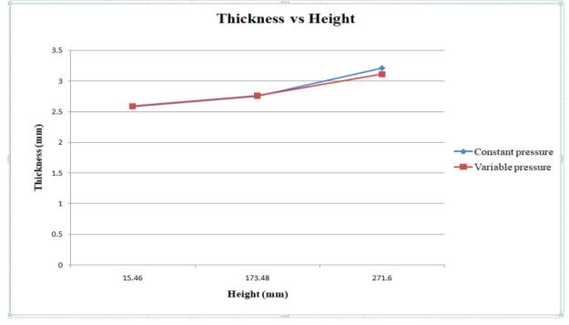
Thefigure6.17showsthethicknessvsheightgraphofthe bothconstantpressureandvariablepressure.Inhorizontal axis represent the height and vertical axis represent the thicknessofthedome.
holderpressureandfrictioncoefficientreducesthethinning of the deep drawn part. At low constant blank holder pressure in the initial stage prevents thinning of the material.Iftheblankholderpressureistoosmallitwillleads to wrinkling in the material. The magnitude of the blank holderpressureintheinitialstagesplaysavitalroleinthe thickness distribution in the drawn part. Then the punch pressure remains constant, an increasing blank holder pressure restrains the wrinkling tendency and enables a smoothflowofmaterialintothediecavity.
Forapplyingthevariableblankholderpressureextrasetup are needed in the industry. Because, as far as industry is concerned only single constant pressure application is possible.Thereisonlysingleinputsetupis possibleinthe industry.Soadditionalsetupsareneededtotheapplication ofvariableblankholderpressureintheindustry.
Chart 2: Thicknessvsheightgraphof19kgcylinder
Inthecaseoftheapplicationconstantpressureinthe14.2 kgcylinder,theresultsindicatesthicknessvariationishigh. But the proposed parameter values reduce the overconsumptionofthematerial.Thebestresultisobtained atfrictioncoefficient0.02andpressureat12Mpa.
Similarlyinthecaseoftheapplicationvariableblankholder pressure in the 14.2 kg cylinder, the results indicates thickness variation is less compare to constant pressure application.Alsotheproposedparametervaluesreducethe overconsumptionofthematerial.Thebestresultisobtained atfrictioncoefficient0.02andpressureininitialstageat10 Mpaandinfinalstageat 12Mpa.
Inthecaseoftheapplicationconstantpressureinthe19kg cylinder,theresultsindicatesthicknessvariationishigh.But theproposedparametervaluesreducetheoverconsumption of the material. The best result is obtained at friction coefficient0.02andpressureat13Mpa.
Similarlyinthecaseoftheapplicationvariableblankholder pressureinthe19kgcylinder,theresultsindicatesthickness variationislesscomparetoconstantpressureapplication. Also the proposed parameter values reduce the overconsumptionofthematerial.Thebestresultisobtained atfrictioncoefficient0.02andpressureininitialstageat10 Mpaandinfinalstageat 13Mpa.
Theapplicationofconstantblankholderpressureincreases the variation between minimum thickness and maximum thickness and it lead to increased thinning at the bottom portion of the cup. whereas, the proposed variable blank
[1] V.Sravani,M.Alekya(2020),Simulationandoptimization ofdeepdrawingprocessparametersforcylindricalcup byusingFEMandtaguchi,JournalofInterdisciplinary CycleResearch,ISSNNO:0022 1945.
[2] Chandra Pal Singh, Geeta Agnihotri (2017), Finite elementanalysisofdeepdrawingprocesstoinvestigate effect of friction, ijmet, Volume 8, Issue 10, October 2017,pp.759 767.
[3] R.Padmanabhan,M.C.Oliveira,J.L.Alves,L.F.Menezes (2008),Numericalsimulationandanalysisonthedeep drawingofLPGbottles,journalofmaterialsprocessing technology200(2008)416 423.
[4] P Venkateshwar Reddy, Perumalla Janaki Ramulu, G SandhyaMadhuri,DasariGovardhan,PVSRamPrasad (2016),DesignandAnalysisofDeepDrawingProcesson angular Deep Drawing Dies for Different Anisotropic Materials,IOPConf.Series.
[5] Anubhav Singh, Shamik Basak, Lin Prakash P.S, Gour Gopal Roy, Maha Nand Jha,Martin Mascarenhas, Sushanta Kumar Panda (2018),Prediction of earing defectanddeepdrawingbehaviorofcommerciallypure titanium sheets using CPB06 anisotropy yield theory, Elsevier,256 267.
[6] Sandip chaudhary, Dhaval shah (2015), A Review on Influence of the effect of process parameters in deep drawing,ijar,volume5,issue1.
[7] AdnanI.O.Zaid(2017),EffectofDifferentLubricantson DeepDrawingofGalvanizedSteel,InternationalJournal ofScientific&EngineeringResearch,Volume8,Issue1, January 2017.
International Research Journal of Engineering and Technology (IRJET) e ISSN: 2395 0056
Volume: 09 Issue: 07 | July 2022 www.irjet.net p ISSN: 2395 0072
[8] AlokTom,GeoMathewPius,GeorgeJoseph,JacobJose andMathewJJoseph(2014), DesignandanalysisofLPG cylinder,InternationalJournalofEngineering&Applied Sciences(IJEAS),Vol.6,Issue2(2014)17 31.
[9] Dr.R.VenkatReddyand V.Mounika(2017), EffectOf VariousProcessParametersOnPunchAndDieDesignIn DeepDrawingProcess,(IJITR)Internationaljournalof innovativetechnologyandresearch,VolumeNo.5,Issue No.6,October November2017,7684 7691.
[10] HusseinZein andOsamaM.Irfan(2021),Optimization and Mapping of the Deep Drawing Force Considering FrictionCombination,MDPI, Appl.Sci.2021,11,9235.