International Research Journal of Engineering and Technology (IRJET) e-ISSN: 2395-0056
Volume: 09 Issue: 07 | July 2022 www.irjet.net p-ISSN: 2395-0072
ANALYSIS OF CONCRETE FILLED HYBRID FOUNDATION
Aleeda Shaju1 , Neethu Joseph2
1Mtech Student, Dept. of Civil Engineering, St. Joseph’s College of Engineering and Technology, Palai 2Assistant Professor, Dept. of Civil Engineering, St. Joseph’s College of Engineering and Technology, Palai ***
Abstract wind power industry has the higher stability and low civil complaints contrast with inland wind farms and also consider as a reliable energy source rather than sustainable energy.Theseenergysystemsdemandmorerobust design and execution than the onshoreturbine. InthisprojectI am presenting a new concept, i.e. Concrete Filled Hybrid Foundation (CFHF). The CFHFisanimprovedversionofhybrid foundation. The main components of the foundation are double skin monopile, wide shallow bucket and radial stiffeners. The double skin monopile isfilledwithconcrete The parametric study of various parameters of CFHFiscarriedout and their maximum horizontal displacement and moment bearing capacity of CFHF is studied in detail. The all parameters will reducethemaximumhorizontaldisplacement and increase the moment bearing capacity.
Key Words: Wind Power, Concrete Filled Hybrid Foundation, , Hybrid Foundation ,Double Skin Monopile, Wide Shallow Bucket And Radial Stiffeners.
1. INTRODUCTION
TheOffshoreWindPower(OWP)industryisoneofthe fastestgrowingenergysystemsinthisera.Thisindustryhas thehigherstabilityandlow civil complaintscontrast with inland wind farms and also consider as a reliable energy sourceratherthansustainableenergy.Theseenergysystems demandmorerobustdesignandexecutionthantheonshore turbine.Windisa secondarysourceofsustainableenergy dependentsonthesun.Thewindvelocityanditsdirection are influence by topographical features, temperature gradientandrevolutionoftheearth.
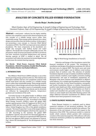
CurrentlyEuropeisthegloballeader inoffshorewind energy sector. The first offshore wind farm (i.e. Vindeby) wasinstalledinDenmarkin1991.AccordingtotheGlobal Wind Energy Council’s (GWEC) report the global OWP marketcapacitygrownfrom29.2gigawatt(in2019)to35 gigawatt (GW) and the current OWP capacity is 35.3 GW where United Kingdom has 29% of the global installation capacity.“HornseaProjectOne”isoneofthelargestoffshore windprojectsinUnitedKingdomwhichhasthecapacityof 1.2 GW. According to the statistics the global OWP installationcapacitywill exceedtwothousandgigawatt in 2050.CurrentlyourIndiahasnooperationalOWPplantbut thefirstonegigawatOWPprojectwasplannedinGujarat. Fig1showsthedevelopmentof thedevelopmentofwind turbine.
Fig 1:WindEnergyInstallationsinYears[7]
Selectionanddesignofthefoundationcontrolthe financial soundness of the project. The investment in installationanddesignoffoundationsconstitutes20 30%of the total cost of a typical OWP. The harsh wave and wind environment results higher cost of offshore wind turbine projects than of onshore ones. The selection of suitable foundationdependsontypeofseabed,installationmethods, oceanicclimaticcondition,waterdepths,economics,loading characteristics and type of installation equipments etc. Monopileisthemostcommonusedfoundationinoffshore windindustry.Itisasimpletypefoundationconsistsoflarge diameter steel tube. Gravity based foundation, monopoles and bucket foundations (known as shallow foundations) usedforwaterdepthupto30m. Jacketfoundationsareused for water depth up to 60m.These foundations are fixed in seabed and classified into grounded systems. For deeper watersorwaterdepthmorethan60mfloatingsystemwill adopt. Different innovative foundations for offshore wind turbineshavebeenproposedinrecentyears.
2. FINITE ELEMENT MODELING
Finite Element Analysis is a methods used to obtain numerical solutions of real practical problems. The soil domainiscreatedascontinuummodelinthesoftware.The dimension of the soil domain is fixed with respect to the dimensionoftheCFHF.Thecontinuummodelisamaterial model, which contains infinite particle with continuous variationofthematerialproperties.FEAsoftwarewillsolve continuummechanicsproblems bysubdividingthemodel intofiniteelements.
© 2022, IRJET | Impact Factor value: 7.529 | ISO 9001:2008 Certified Journal | Page832

International Research Journal of Engineering and Technology (IRJET) e ISSN: 2395 0056
2.2 Validation
In order to validate the method, the finite element analysesofmonopileandhybridfoundationarecarriedout andtheobtainedresultsarecomparedwiththejournalChen et.al[1].
2.3 Validation of Monopile
To validate numerical modeling of this project, a finiteelementanalysisofmonopilefoundation[1]isfound and these results compare with present model. In this validation,thediameterofmonopile(D1)istakenas6mand correspondingembedmentlength(L)istakenas44.5m.The soil domain diameter is set as 20D1 and corresponding depth is 1.5L. The monopile foundation is modeled with threedimensionaleightnodelinearbrickelement(C3D8R) and it is made with steel. And normally consolidated silty sandprofilewithMohrCoulombmodelwasadoptedforthe validation.Thepropertiesofmonopileandsoildomainare giveninTable1.
Table 1: Propertiesofmonopileandsoildomain[1]
Soil Properties Monopile Properties
Youngsmodulus:13.4MPa Youngsmodulus:210GPa Poisson’sratio:0.3 Poisson’sratio:0.3 Cohesion:32kPa Density:78.5kN/m3
Frictionangle:270 Unitweight:8.7kN/m3
Thebottomboundaryofsoildomainiskeptasfixed, the horizontal displacements are restrained for lateral direction.Sincethegeometryofthemodelissymmetric,only half of the whole model is take for the analysis and the symmetricalconstrainisappliedtosymmetricalplain.The design wind and current load is applied in the form of horizontal load (H), and then horizontal load 3.5 MN is applied at an eccentricity 6 m from the reference point. Weightofsuperstructureisrepresentedbyverticalload(V) anditistakenas451.5t.Thenthemonopilewasmodeled andanalyzedinABAQUS.
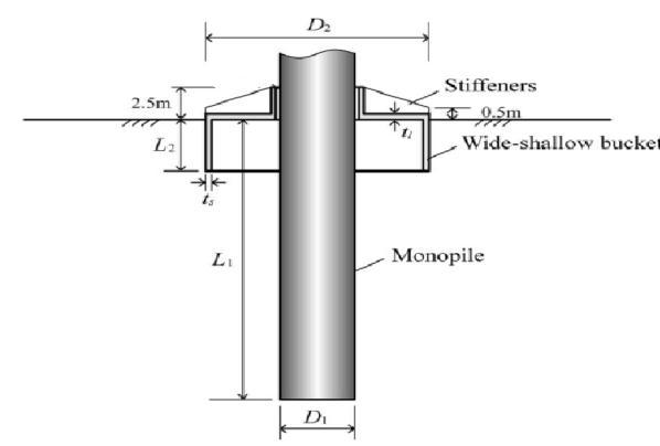
TheresultsobtainedfrompresentstudyandChen et.al (2020) on monopile foundation are plotted and compared. The moment rotation graphs of both present study and Chen et.al (2020) shown in Fig 2. The results show some variations (less than 10%) due to the assumptions of unknown data. The comparison between presentstudyandthatintheChenet.al(2020)showshigh levelofagreement.
Fig -2:Moment rotationgraphofmonopile
2.3 Validation of Hybrid Foundation
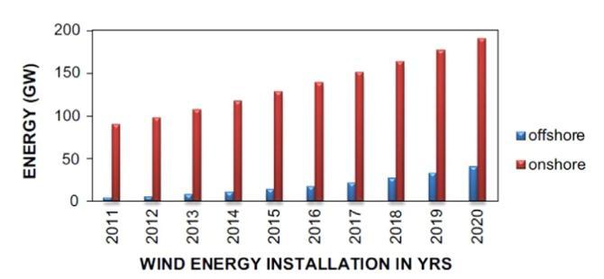
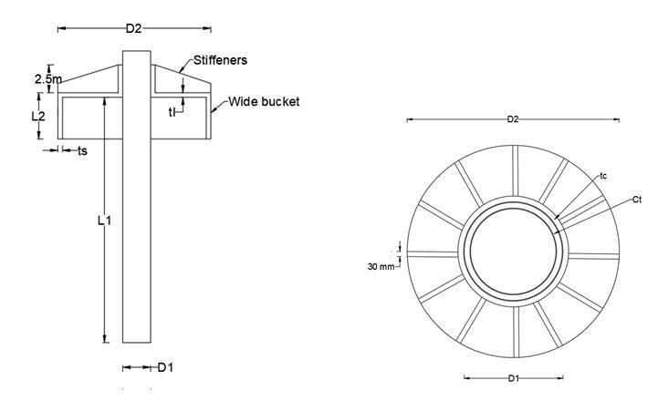
Similartomonopilefoundation,thefiniteelement analysisofhybridfoundation[1]isfoundandtheseresults comparewithpresentmodel.Inthisvalidation,thediameter of monopile (D1) is taken as 6m and corresponding embedmentlength(L)istakenas25m.Thediameterofthe wide bucket (D2) is taken as 15m and corresponding embedment length (L2) is taken as 3m. The schematic representationhybridfoundationisshowninFig.3..Thesoil domaindiameterissetas10D2andcorrespondingdepthis 1.5L1.
Fig 3:Theschematicrepresentationhybridfoundation [1]
Volume: 09 Issue: 07 | July 2022 www.irjet.net p ISSN: 2395 0072 © 2022, IRJET | Impact Factor value: 7.529 | ISO 9001:2008 Certified Journal | Page833
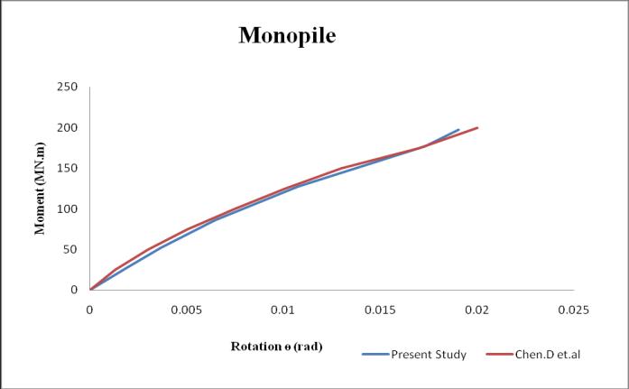
TheresultsobtainedfrompresentstudyandChen et.al (2020) on monopile foundation are plotted and compared. The moment rotation graphs of both present studyandChenet.al(2020)showninFigure4.Theresults show some variations (less than 10%) due to the assumptions of unknown data. The comparison between presentstudyandthatintheChenet.al(2020)showshigh levelofagreement.
International Research Journal of Engineering and Technology (IRJET) e ISSN: 2395 0056
Volume: 09 Issue: 07 | July 2022 www.irjet.net p ISSN: 2395 0072
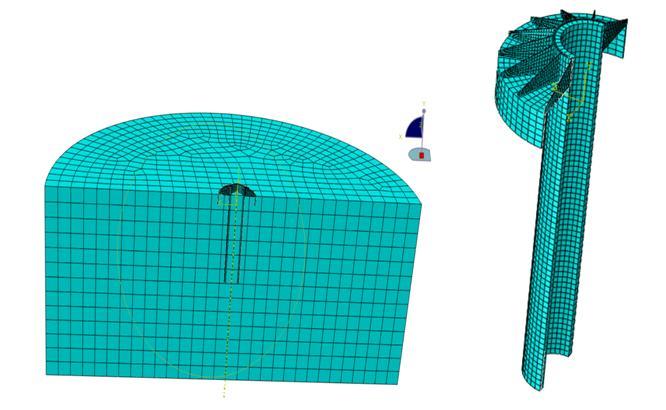
Inthisanalysissoildomaindiameterissetas10D2and corresponding depth is 1.5L1. The CFHF is modeled with threedimensionaleightnodelinearbrickelement(C3D8R) and it is made with steel.Fig.6 shows FE meshes of CFHF. AndMohrCoulombmodelwasadoptedforthisstudy.
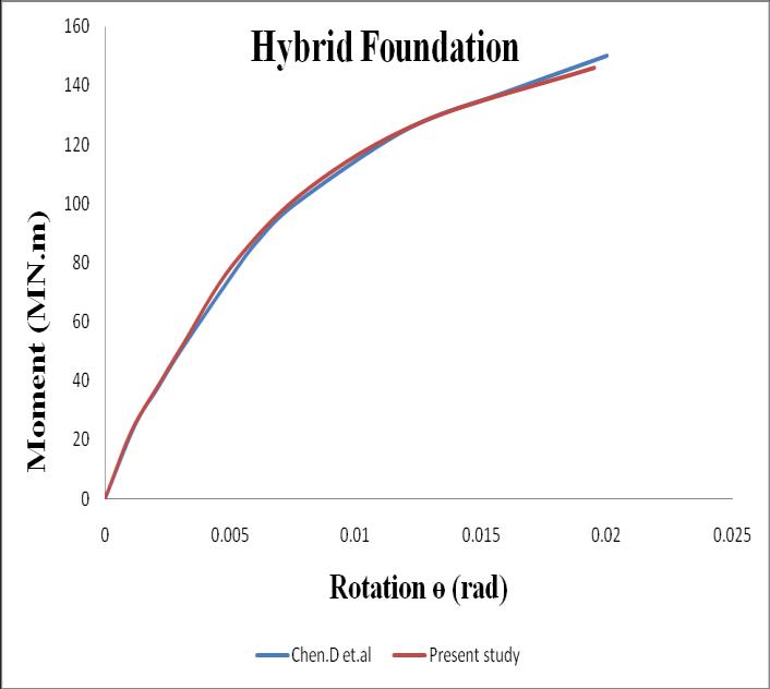
Fig 4:Moment rotationgraphofhybridfoundation
3. CONCRETE FILLED HYBRID FOUNDATION
InthisprojectIampresentinganewconcept,i.e.Concrete FilledHybridFoundation(CFHF).TheCFHFisanimproved versionofhybridfoundation.Themaincomponentsofthe foundationaredoubleskinmonopile,wideshallowbucket andradialstiffeners.Thedoubleskinmonopileisfilledwith concrete. The outer part of the double skin monopile surroundedbywidebucketandthestiffenersarearrangedin radialpatternanditislocatedonlidofthebucket.Andthe concrete s filled in between double s The schematic representationofCFHFisshowninFig 5.
Fig 6:LoadsonMonopileFoundation[6]
Thebottomboundaryofsoildomainiskeptasfixed,the horizontaldisplacementsarerestrainedforlateraldirection. Sincethegeometryofthemodelissymmetric,onlyhalfof thewholemodelistakefortheanalysisandthesymmetrical constrainisappliedtosymmetricalplain.Thedesignwind andcurrentloadisappliedintheformofhorizontalload(H), andthenhorizontalload3.5MNisappliedataneccentricity 6 m from the reference point. Weight of superstructure is representedbyverticalload(V)anditistakenas451.5t
3.2 Parametric Study on CFHF
Fig 5:SchematicrepresentationofCFHF
3.1 CFHF Model
ThedetailedschematicrepresentationofCFHFisshown in Fig.3.6 .Here D1 is the outer diameter of double skin monopile and L1 is corresponding embedment length. Wheretp,tl,tsarerepresentingthethicknessofmonopile,lid andskirtsrespectively.D2isthediameterofwidebucket, L2 is the embedment length of wide bucket and Ct is the concrete thickness. A 3 MW turbine is used for present study.
TheparametricstudyofvariousparametersofCFHFis carriedoutandtheirmaximumhorizontaldisplacementand moment bearingcapacityof CFHF isstudiedindetail.The parametersusedforthestudyarediameterofdoubleskin monopile (D1), wide bucket diameter (D2) and concrete thickness(Ct).Andthicknessofmonopile,lidandskirtsare kept as fixed throughout the analysis. And embedment length of double skin monopile and wide bucket are also keptasfixed.TherangeofCFHFparametersselectedforthe studyisshown in theTable 2.And Table3. shows model namesandparametersofCFHFmodel.
Table -2: Parametersselectedforthestudy
CFHFParameter RangeSelected
Doubleskinmonopile diameter(D1), 4mto7m
Widebucketdiameter(D2) 11mto13m Concretethickness(Ct). 0.11mto1m
International Research Journal of Engineering and Technology (IRJET)
e ISSN: 2395 0056
Table 2: Parametersselectedforthestudy
Setname Modelname D1 D2 Ct
Set1
Set2
Set3
Set4
Set5
Set6
Set7
Set8
HFD4d11Ct1 4 11
0.11 HFD4d11Ct2 0.25 HFD4d11Ct3 0.51 HFD4d11Ct4 1
HFD5d11Ct1 5
0.11
HFD5d11Ct2 0.25 HFD5d11Ct3 0.51 HFD5d11Ct4 1
Similarly in the wide bucket soil and wide bucket pile interactions,thewidebucketisassignasthemastersurface ofeachinteractionandcorrespondingslavesurfacesaresoil and pile respectively. In Pile concrete interaction, pile is definedasthemastersurfaceandconcreteassignedasthe slavesurface.Inthispresentstudyinterfacecontactistaken as‘hardcontact’andthereisnoseparationisallowed.
4. EXPERIMENTAL VALIDATION
HFD6d11Ct1 6 11
0.11 HFD6d11Ct2 0.25 HFD6d11Ct3 0.51 HFD6d11Ct4 1
0.11 HFD7d11Ct2 0.25 HFD7d11Ct3 0.51 HFD7d11Ct4 1
HFD7d11Ct1 7 11
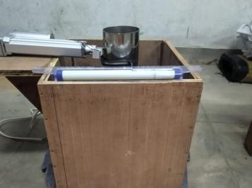
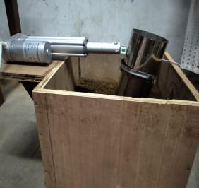
In this section numerical modeling ( Finite element method) is validated with real experiment. And the computedresultsobtainedfromFEAiscomparedwiththe experimental result. In this validation, the diameter of monopile (D1) is taken as 8cm m and corresponding embedmentlength(L)istakenas25cm.Thelength,breadth and depth of soil domain are 25 cm x 25 cm x 25cm respectively. The loose soil is used for this study. The monopileisplacedatthecenterofsoildomain.Theactuator isusedtoprovidethehorizontalloadtothesystemandthe correspondinghorizontalloadismeasuredbytheloadcell. Fig7showsdifferentstagesoftheexperiment
HFD4d13Ct1 4 13
0.11 HFD4d13Ct2 0.25 HFD4d13Ct3 0.51 HFD4d13Ct4 1
HFD5d13Ct1 5 13
0.11 HFD5d13Ct2 0.25 HFD5d13Ct3 0.51 HFD5d13Ct4 1
HFD6d13Ct1 6 13
0.11 HFD6d13Ct2 0.25 HFD6d13Ct3 0.51 HFD6d13Ct4 1
HFD7d13Ct1 7 13
0.11 HFD7d13Ct2 0.25 HFD7d13Ct3 0.51 HFD7d13Ct4 1
3.3 Soil Structure Interaction on CFHF
SoilStructureInteraction(SSI)ofCFHFisoneofthemain part of this study. The soil pile and wide bucket soil are modeledbysurfacetosurfacecontact.Pile concreteandpile towidebucketaremodeledbynodetonodeinteraction.In pile soilinteractionpileisdefinedasmastersurfaceandthe soilsurfacecontactwithpileisassignedasslavesurface.
5. RESULT AND DISCUSSION
Volume: 09 Issue: 07 | July 2022 www.irjet.net p ISSN: 2395 0072 © 2022, IRJET | Impact Factor value: 7.529 | ISO 9001:2008 Certified Journal | Page835
This chapter is mainly deals with numerical results of CFHF.Theresultsmayincludelateraldisplacementandthe momentrotationgraph.Andalsoinvestigateitsinfluencein monopile diameter, wide bucket diameter and concrete thickness.
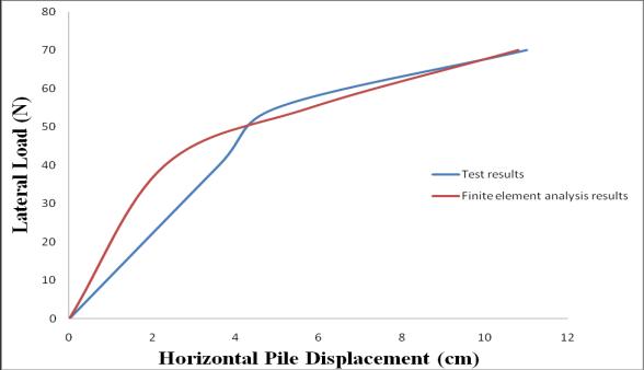 Fig 7Beforeandafterhorizontalloading
Fig 8ComparisonoftestresultsandFEA results
Fig 7Beforeandafterhorizontalloading
Fig 8ComparisonoftestresultsandFEA results
International Research Journal of Engineering and Technology (IRJET) e ISSN: 2395 0056
Volume: 09 Issue: 07 | July 2022 www.irjet.net p ISSN: 2395 0072
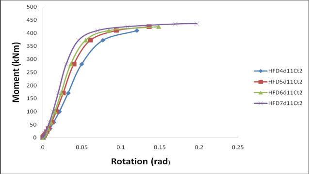
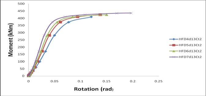
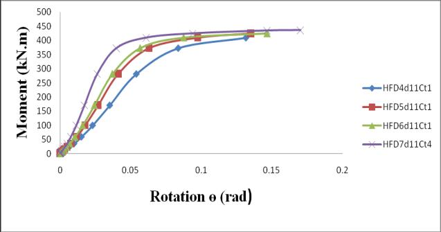

TheFig9(a)showstheM RgraphofCFHFwithdifferent doubleskinmonopilediameterandthicknessofconcreteis keptas0.11mandwidebucketdiameteris11m.TheFig9 (b)showstheM RgraphofCFHFwithdifferentdoubleskin monopile diameter and thickness of concrete is kept as 0.25mandwidebucketdiameteris11mTheFig9(c)shows theM RgraphofCFHFwithdifferentdoubleskinmonopile diameter and thickness of concrete is kept as 0.51m and widebucketdiameteris 11m TheFig9(d)showsthe M R graphofCFHFwithdifferentdoubleskinmonopilediameter and thickness of concrete is kept as 1m and wide bucket diameter is 11m. The Fig 9 shows the ultimate moment carrying capacity of CFHF is increased with increasing monopile diameters. The diameter 7m shows maximum momentbearingcapacity,BecausethestiffnessoftheCFHF is directly influenced by diameter of the steel pile. It also reducethemaximumhorizontaldisplacementofCFHF.
(a) (b) (c)
International Research Journal of Engineering and Technology (IRJET) e ISSN: 2395 0056
Volume: 09 Issue: 07 | July 2022 www.irjet.net p ISSN: 2395 0072
The concrete thickness has less impact in moment capacity. Andhavinglargeimpactonreducehorizontal displacements.
REFERENCES
[1] Chen,D.,Gao,P.,Huang,S.,Li,C.andYu,X.,(2020).“Static anddynamicloadingbehaviorofahybridfoundationfor offshore wind turbines”. Marine Structures, Vol.71, pp.102727
(d)
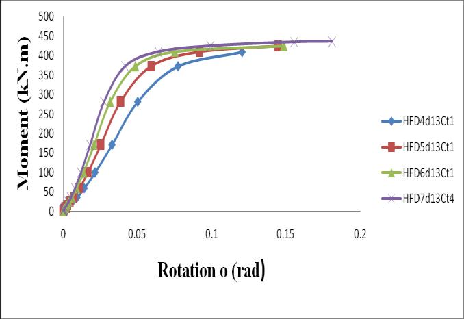
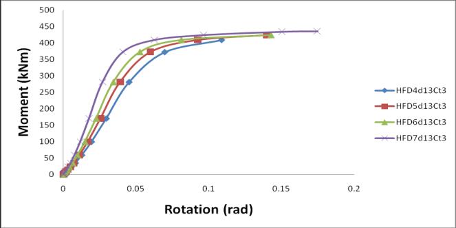
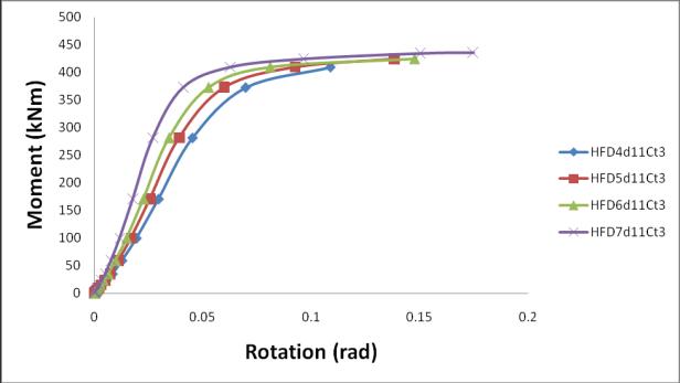
Fig 10:MomentRotationgraphof 13mwidebucket
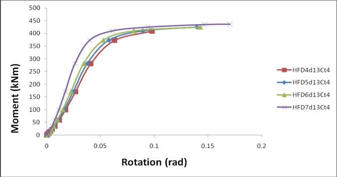
The Fig 10 (a) shows the M R graph of CFHF with different double skin monopile diameter and thickness of concreteiskeptas0.11mandwidebucketdiameteris13m. TheFig10(b)showstheM RgraphofCFHFwithdifferent doubleskinmonopilediameterandthicknessofconcreteis keptas0.25mandwidebucketdiameteris13mTheFig10 (c)showstheM RgraphofCFHFwithdifferentdoubleskin monopile diameter and thickness of concrete is kept as 0.51m and wide bucket diameter is 13m The Fig 10 (d) shows the M R graph of CFHF with different double skin monopilediameterandthicknessofconcreteiskeptas1m and wide bucket diameter is 13m. The Fig 10 shows the ultimatemomentcarryingcapacityofCFHFisincreasedwith increasing monopile diameters. The diameter 7m shows maximummomentbearingcapacity,Becausethestiffnessof theCFHFisdirectlyinfluencedbydiameterofthesteelpile. It also reduce the maximum horizontal displacement of CFHF.
BycomparingbothFig9andFig10,themomentbearing capacity of CFHF will increases with the increasing wide bucket diameters. The thicknessofconcrete alsohave the positive influence on the moment bearing capacity. This combinationofCFHFwillreducetherotationoftheCFHF
6. CONCLUSIONS
Fromtheparametricstudy,thefollowingconclusionsare obtained:
As the monopile diameter increases and other parameters are keeping constant, then the bearing capacity and rotation of CFHF increases. And the monopile having 4m diameter shows large rotation than7mdiameter.
[2] Ma,H., and Yang,J.,(2020). “ A novel hybrid monopile foundation for offshore wind turbines. Ocean Engineering,Vol.198,pp.106963
[3] Wang, X., Zeng, X., andLi, J., (2019). “Vertical performanceofsuctionbucketfoundationforoffshore windturbinesinsand”.OceanEngineering,Vol.180,pp. 40 48.
[4] Velarde, J., Kramhøft, C., and Sørensen, J.D., (2019). “Global sensitivity analysis of offshore wind turbine foundationfatigueloads”.RenewableEnergy,Vol.140, pp.177 189.
[5] Ahmed, S.S, and Hawlader, B.,(2016). “Numerical Analysis of Large Diameter Monopiles in Dense Sand Supporting Offshore Wind Turbines”. International Journal of Geomechanics,,pp.04016018 doi:10.1061/(ASCE)GM.1943 5622.0000633
[6] Bhattacharya,S. (2019), “ Design of Foundations for OffshoreWindTurbines”,Wiley,USA.
[7] Perveen,R,Kishor,N,.andMohanty,SR.,(2004)“Off shore wind farm development: present status and challenges”.RenewSustainEnergyRev,Vol.29,pp.780 792.
[8] Achmus,M., Kuo,Y.S., and Abdel Rahman,K. ,(2009). “Behaviorofmonopilefoundationsundercycliclateral load”.ComputGeotech,Vol.36(5),pp.725 35.
[9] Zaaijer,M.,(2002)“Sensitivityanalysisforfoundations ofoffshorewindturbines”.SectWindEnergy,TUDelft
[10] Nikitas,G.,Vimalan,N.J.,and Bhattacharya,S.(2016). “Aninnovativecyclicloadingdevicetostudylongterm performanceofoffshorewindturbines”.SoilDynamics and Earthquake Engineering,Vol.82, pp. 154 160. doi:10.1016/j.soildyn.2015.12.008
Thewidebucketdiameteralsohavethepositiveimpact on moment bearing capacity. The variation of wide bucketdiameterhaslessimpactontherotation.
[11] RP2A WSD A Recommended practice for planning, designing and constructing fixed offshore platforms working stress design . Paper presented at: Twenty 2000.
International Research Journal of Engineering and Technology (IRJET) e ISSN: 2395 0056
[12] Negro,V.,López Gutiérrez,J.S.,Esteban,M.D.,Matutano, C., (2014). “Uncertainties in the design of support structuresandfoundationsforoffshorewindturbines”. RenewableEnergy,Vol.63,pp.125 132. doi:10.1016/j.renene.2013.08.041
[13] Cox,J.A.,Bhattacharya,S.,andLombardi,D.,WoodMuir Wood,D.M.,(2013).“Dynamicsofoffshorewindturbines supportedontwofoundations”.ProceedingsoftheICE Geotechnical Engineering,Vol.166(2),pp.159 169. doi:10.1680/geng.11.00015
[14] Wu,X.,Hu,Y.,Li,Y.,Yang,J.,Duan,L.,Wang,T.,Adcock,T., Jiang,Z.,Gao,Z.,Lin,Z.,Borthwick,A.,andLiao,S.,(2019). “Foundations of offshore wind turbines: A review” Renewable and Sustainable Energy Reviews,Vol. 104, pp.379 393.doi:10.1016/j.rser.2019.01.012
[15] Hermans, K, and Peeringa ,J. “Future XL monopile foundation design for a 10 MW wind turbine in deep water”,(2016) Technical Report, ECN E 16 069. The Netherlands:ECN;
[16] Malhotra,S.(2011).“Selection,designandconstruction ofoffshorewindturbinefoundations.”WindTurbines,I. Al Bahadly,ed.,InTech,Rijeka,Croatia
[17] Thomsen,K.,(2014).“Offshorewind:acomprehensive guide to successful offshore wind farm installation”. AcademicPress;
[18] Castro Santos ,L,and Diaz Casas, V.,(2006). “ Floating offshorewindfarms”.SpringerInternationalPublishing
[19] DNV. “Design of offshore wind turbine structure”.(2010)DetNorskeVeritasAS.
[20] Lian,J.,Chen,F.,andWang,H.,(2014) “Laboratorytests onsoil skirtinteractionandpenetrationresistanceof suction caissons during installation in sand”. Ocean Eng.Vol.84,pp.1 13
[21] Dong ,W, Moan, T, and Gao,Z.,(2011). “ Long term fatigueanalysisofmulti planartubularjointsforjacket type offshore wind turbine in time domain”. Eng Struct,Vol.33,pp.2002 14
[22] Harris,J.M.,WhitehouseRJS.(2017)“Scourdevelopment around large diameter monopoles in cohesive soils: evidence from the field”. J Waterw Port Coast Ocean Eng,Vol.143(5)
[23] De,V.L., De,R. J, Troch ,P,and Frigaard,P.,(2011) “Empiricaldesignofscourprotectionsaroundmonopile foundations: part 1: static approach”. Coast Eng,Vol.58(6),pp.540 53
Volume: 09 Issue: 07 | July 2022 www.irjet.net p ISSN: 2395 0072 © 2022, IRJET | Impact Factor value: 7.529 | ISO 9001:2008 Certified Journal | Page838
[24] Achmus,M.,Akdag,C.T.,andThieken,K.(2013).“Load bearingbehaviorofsuctionbucketfoundationsinsand”. ApplOceanRes,Vol.43(5),pp.157 65.
[25] Wang, X, Yang ,X, and Zeng,X., (2017). “Seismic centrifuge modelling of suction bucket foundation for offshorewindturbine”.RenewEnergy,Vol.114.