International Research Journal of Engineering and Technology (IRJET) e ISSN: 2395 0056

Volume: 09 Issue: 07 | July 2022 www.irjet.net p ISSN: 2395 0072
International Research Journal of Engineering and Technology (IRJET) e ISSN: 2395 0056
Volume: 09 Issue: 07 | July 2022 www.irjet.net p ISSN: 2395 0072
1M.Tech Student, Dept. of Civil Engineering, PES College of Engineering, Mandya, Karnataka, India 2Professor, Dept. of Civil Engineering, PES College of Engineering, Mandya, Karnataka, India 3Assistant Professor, Dept. of Civil Engineering, Government Engineering college Kushalnagar, Karnataka, India ***
Abstract When a structure is exposed to natural hazards such as earthquakes, high winds, Tsunamis, andsoon, orman made hazards such as fire, gas explosions, vehicle collisions, terrorist attacks, and so on, its stability is compromised. Progressive Collapse refers to the process of local failure leading to global failure. In this study, an RCC structure with “S” shaped plan with shear walls is used for Progressive Collapse analysis. AccordingtoGeneralServiceAdministration (G.S.A.) guidelines, the columns are removed one by one at the interior, exterior, and corner regions. Linear dynamicanalysis is performed using the ETABS software version 15.2. In the critical region of the structure associated with the column removal, the Demand Capacity Ratio (DCR) and Interaction Ratio are calculated. According to the literature review, the most critical case for progressive failure is interior column removal at the base, and the least critical case is corner column removal at the base.
Key Words: Progressive Collapse, Column Removal, Demand Capacity Ratio, ETABS, GSA Guidelines, DOD Guidelines,InteractionRatio,LinearstaticAnalysis
Structures are built to withstand extreme forces and stresses. However, when the load acting on an element exceeds its ultimate value, a member fails. When a load bearingstructuralmemberinabuildingfails,itcausesthe failureofsomeotheradjacentmembers,andthefailureof those adjacent members causes the failure of some more adjacent or higher storey members, and so on until the entirestructurefails.ThisisknownasProgressive Collapse orProgressiveFailure.
The analysis can be performed by removing one or more verticalloadcarryingelements.Extremeloadingofnormal and abnormal loads causes progressive failure. The main causeofprogressivefailureisabnormalloads,whichinclude gas explosion loads, wind overpressure loads, blast loads, earthquakeloads,andsoon.Whenabuildingissubjectedto abnormalloads,thestructuralelementsarethefirstto be damaged. When a vertical member, such as a column, is damaged due to a sudden impact of load, the load is distributedtootheradjacentorneighboringelements.Ifthe adjacent members are strong enough to withstand the
additionalloadTherewillbenofailure,butiftheycannot,a memberwillfail.
1. The structure should be designed as a redundant structure,sothatifanyofthecolumnsfails,thereis anotherwaytodistributetheloadseffectivelyand thestructurecanwithstandthelossofanymember.
2. Providinglocalresistance,whichentailsusingsome extraelementstoconnectthestructuralelementsso that the structure can effectively transfer or redistributeforces.
3. Themembersshouldbeeffectivelyinterconnected so that forces can transfer without causing any damage. This is nothing more than increasing redundancyorlocalresistance.
Themaingoalofthisguidelineistoensurethatthefailure occursatthebeginning,whichisreferredtoasalocalfailure, and that this local failure is limited to some damage less point so thattheglobal failure, or wholestructure failure, can be stopped. First, this guidance provides an analysis proceduretodeterminewhetherornotthebuildingissafe basedonbuildingusage,load,andotherparameters.Ifthe structure passes the analysis, it is referred to as safe; otherwise,columnsareremovedatspecificlocationsandthe resultsareevaluatedtoensurethestructure'sresistanceto progressivecollapse
GSAspecifiescolumnremovallocationsas
1. exterior column removal in buildings in both the longerandshorterdirections.
2. Buildinginteriorcolumnremoval.
3. Buildingcornercolumnremoval
International Research Journal of Engineering and Technology (IRJET) e ISSN: 2395 0056
Volume: 09 Issue: 07 | July 2022 www.irjet.net p ISSN: 2395 0072
1. Beforecolumnremovaltheloadcombinationtobe consideredisDL+LL
2. Aftercolumnremovalforlinearstaticanalysisthe loadcombinationtobeconsideredis2(DL+0.25LL)
3. After column removal for linear dynamic analysis theloadcombinationtobeconsideredisDL+0.25LL
1. It is appropriate for structures subjected to abnormalloadsbecauseitisadynamicphenomenon. Asaresult,dynamicanalysisbecomesnecessary.
2. Eventhoughdynamicanalysesareavoidedbecause theyarecomplexandtimeconsuming,theyhavea higher accuracy level than static analyses because they account for amplification factors, inertia, and dampingforces
3. It is also known as Time History analysis and is a step by stepprocedurefordeterminingthedynamic responseofastructuretospecificloadingthatmay varyovertime.
4. Inthisanalysistheloadcombinationis(DL+0.25LL)
5. The D C Ratio of structural members is used to differentiateresults.
6. The disadvantage is that the non linearity of geometryandmaterialisnottakenintoaccount.
1. Create a computer model with the necessary configuration.
2. Removethecolumnsfromthedesignatedlocations.
3. Runtheanalysisusingthedynamicloadcombination specifiedbyG.S.A
4. Thetimehistoryfunctionisusedwithazero starting condition
5. DeterminetheD Cratioofthestructuralmembers based on the peak value calculated from the time historyresponse.
The G.S.A classifies structural members as safe or unsafe based solely on D C Ratio values. If the D C Ratio value is withintheacceptablerange,itissafe;otherwise,itisunsafe. It is defined as the ratio of "force acting on the structural membertothemember'sultimatecapacity".
D CRatio=PULTIMATE /PACTING Where, PACTING denotes the force acting on the element. It couldbeanykindofforce,suchasabendingmoment,shear force,oraxialload.
PULTIMATE=Themember'sultimateforceorcapacityinterms ofShearforceoraxialload.G.S.Alimitsthepermissiblevalue ofG.S.A
FortypicalstructurestoD CRatio=2.0. Foratypicalstructures,D CRatio=1.5
ThelinearanalysisD CRatioisusedtodeterminemember safetyagainstcollapseaswellasfornonlinearanalysis.The rotationoftheplastichingeandthedisplacementductility ratioareused.
As the analysis is a three dimensional frame analysis, the columnsinthiscasearesubjectedtoaxialloadandbiaxial moment.Bi axialbendingismoreprevalentinthebuilding's corner columns. Even though the exact design is difficult, thesecolumnsaredesignedusingtheInteractionratio.The designshouldbedonefortherespectiveloadcombinations, suchas(DL+LL)beforecolumnremovaland2(DL+0.25LL) after column removal. The flexure details, such as rebar percentage,Axial load,andmoments,arethenrecorded.
[MUX/MUX1]n+[MUY/MUY1]n1.00istheinteraction formula.
Where,MUXandMUYarethemomentsaboutthexandy axescausedbythedesignload.
MUX1 and MUY1 are the maximum uniaxial moments for axialloadsaboutthexandyaxes,respectively.
0.45fckAc+0.75fy=Puz Asc
Where,fckandfyaretheconcreteandsteelcharacteristic strengths,respectively. Ac and Asc represent the concrete and steel areas, respectively.
To grasp the concept of progressive failure, different columnsareremovedfromvariouslocations,andvariations in Bending moment, Axial load, and interaction ratio are observedfromfloortofloor.
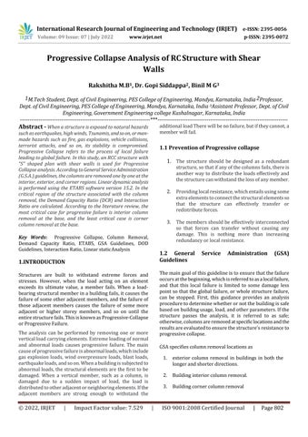
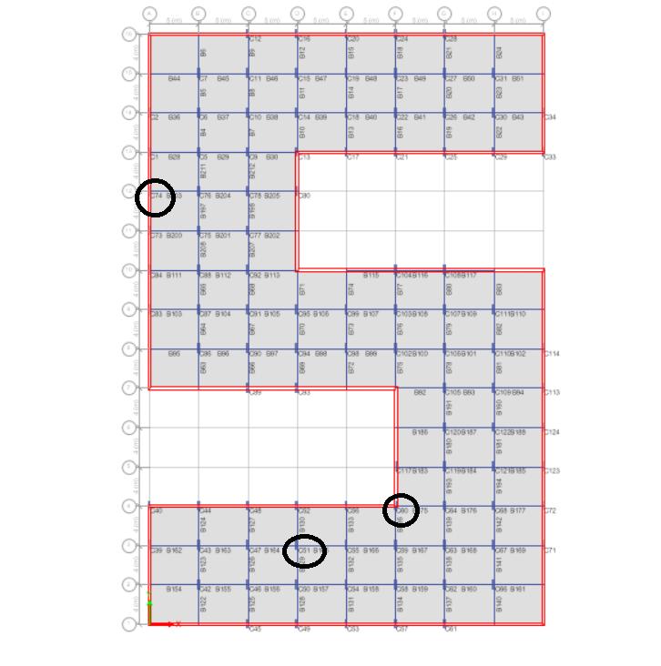
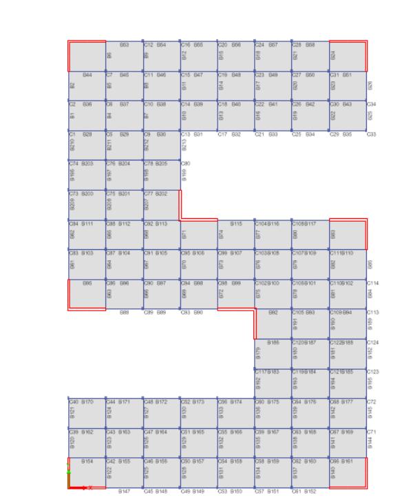
Thestructureisintheshapeofan"S"withbasementfloor, groundfloor,and20storeys,withbaysizesof5 metersin theXdirectionand4metersintheYdirection.Theheightof typicalstoreyare3.2meters,andtheheightofBasestoreyis 3.1meters.Thedimensions ofthebeamsremainconstant across all storeys, but the dimensions of the columns decrease as the floor rises, giving the building geometric irregularity.
The load combinations are taken according to G.S.A guidelines,whichare(DL+LL)forbefore columnremoval casesand2(DL+0.25LL)forthecaseaftercolumnremoval.
International Research Journal of Engineering and Technology (IRJET) e ISSN: 2395 0056
Volume: 09 Issue: 07 | July 2022 www.irjet.net p ISSN: 2395 0072
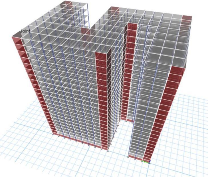
Case 1: Removal of Exterior column C74 atStorey 2
For this case DCR of beams B203, B196, B210 and Interaction ratio of columns C73, C76, C1 needs to be considered.
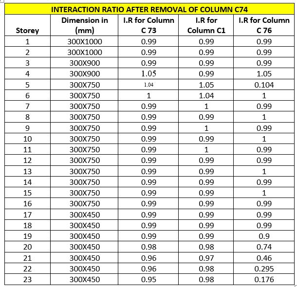
Table 1: InteractionRatioafterremovalofcolumnC 74
Chart 1:D CRatiov/sStoreyforBeamB203
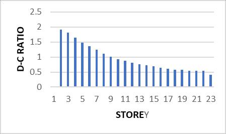
In this case, the DCR value of beam 209 is exceeding the permissiblevalue1.5instoreys2to3exceptotherstories,the DCRvalueofBeam196and210isexceedingthepermissible value1.5instoreys2to6andlieswithinlimitsforremaining storeys. From table 1 we can observe that the interaction ratioofcolumnsadjacenttotheremovedcolumnlieswithin thepermissiblevalue1.0
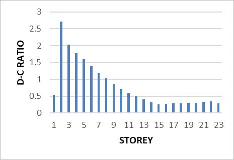
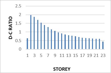
For this case DCR of beams B174, B175, B136, B192 and InteractionratioofcolumnsC56,C64,C59,C117needstobe considered.
Chart 2:D CRatiov/sStoreyforBeamB196
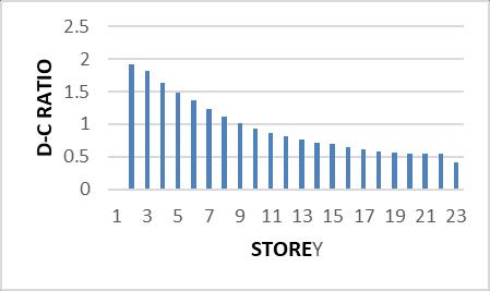
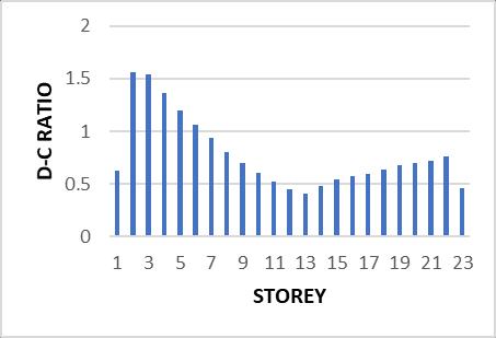
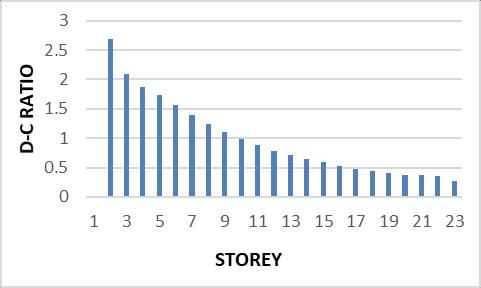
Chart 4:D CRatioV/SStoreyforBeam175
Chart 3:D CRatiov/sStoreyforBeam210
2022, IRJET | Impact Factor value: 7.529 | ISO 9001:2008 Certified Journal
International Research Journal of Engineering and Technology (IRJET) e ISSN: 2395 0056
Volume: 09 Issue: 07 | July 2022 www.irjet.net p ISSN: 2395 0072
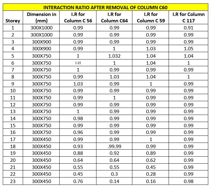
Table -2: Interaction Ratioafterremoval ofcolumnC60
Chart 5:D CRatiov/sStoreyforBeamB174 Chart 6 :D CRatioV/SStoreyforBeam136
In this case, the DCR value of beam B174 and B175,B136,ffffareexceedingthepermissiblevalue1.5in storeys2,3,4,5 exceptotherstorey,DCRvalueofbeam192 isexceedingthepermissiblevalue1.5instoreys1to9and lieswithinlimitsforremainingstoreys.
FromTable2wecanobservethattheInteractionratioof columnsadjacenttotheremovedcolumnlieswithinthe permissiblevalue1.0
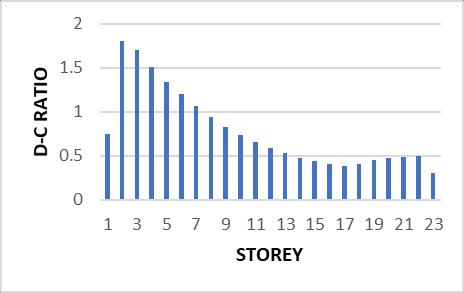
Case 3: Removal of interior column C 51 at storey
ForthiscaseDCRofbeamsB164,B165,B129,B130and InteractionratioofcolumnsC47,C55,C50,C52needstobe considered.
International Research Journal of Engineering and Technology (IRJET) e ISSN: 2395 0056
Volume: 09 Issue: 07 | July 2022 www.irjet.net p ISSN: 2395 0072
Table 3:
afterremoval ofcolumn C51
Chart -9:D CRatiov/sStoreyforBeamB165
Chart 10:D CRatiov/sStoreyforBeamB129
Inthiscase,theDCRvalueofallbeamB164,B165,B129,are exceedingthepermissiblevalue1.5instoreys2to5 andlies withinthelimitforotherstoreys,DCRvalueofbeam130is exceedingthepermissiblevalue1.5instoreys2to9andlies withinlimitsforremainingstoreys
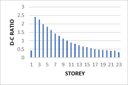
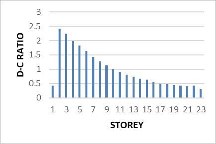
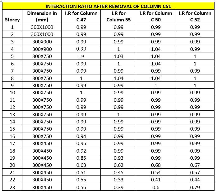
From Table 3 we can observe that the Interaction ratio of columns adjacent to the removed column lies within the permissiblevalue1.0
1. Vertical structural element failure is more dangerous than horizontal structural element failure.
2. Theaxialforceatthebaseisgreaterinthecolumn removedcasethaninthenormalcase,andwecan concludefromthecomparisonoftheresultsofaxial forcewithandwithoutconsideringdynamicfactor that it is better to design the building without considering dynamic factor as that case is more critical.
3. consideringdynamicfactorthatitisbettertodesign thebuildingwithoutconsideringdynamicfactoras thatcaseismorecritical.
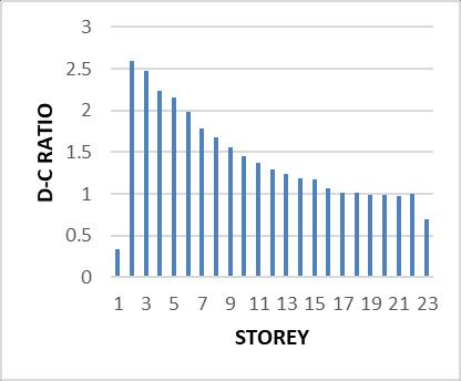
Chart -11:D CRatiov/sStoreyforBeamB130
4. The interior column removal case at the base is discovered to be the most critical case for progressivefailure.
International Research Journal of Engineering and Technology (IRJET) e ISSN: 2395 0056
5. Forthestructureunderconsiderationinthispaper, theD CRatioforbeamexceedsthelimitonlyfor the upper 2 6 floors; the values for the remaining storeysarewithinthelimit.
[1] Binil M G, Dr. H. J. Puttabasave Gowda, “Progressive Collapse analysis of Reinforced Concrete Structure” International Research Journal of Engineering and Technology(IRJET),e ISSN:2395 0056,p ISSN:2395 0072,Volume:08Issue:05|May2021
[2] Rakshith K G, Radhakrishna, “Progressive Collapse Analysis of Reinforced Concrete Framed Structure”, International Journal of Research and Technology, e_ISSN:2319 1163,p_ISSN:2321 7308,November2013.


[3] Samrat prakash khokale, Prof.Mrs.U.R.Kawade, “Progressive CollapseofHighriseRCCstructureunder Accidentialloads”.InternationalJournalofLatesttrends In Engineering and technology (IJLTET) ISSN: 2278 621X,Vol3,DOI:4March2014.
[4] ZHANG Peng, CHEN Baoxu, “Progressive Collapse analysis of Reinforced Concrete Structure in Linear staticAnalysisbasedonG.S.A”2013ThirdInternational Conference on Intelligent System design and EngineeringApplications, DOI 10.1109/ISDEA.2012.253,©2012IEEE,China.
[5] LIZhongxian,SHIYanchoa,“Methodsfor Progressive CollapseAnalysisofBuildingStructuresunderBlastand Impactloads”,TransactionsofTianjinUniversity2008, Vol15No52008,DOI 10.1007/s12209 008 0056 0,
[6] M. Lupoae, C Baciu, D Constantin, H Puscau, “Aspects ConverningProgressiveCollapseofReinforcedConcrete frame Structure with Infill walls” Proceedings of the WorldCongressonEngineering2011Vol.шWCE2011, July6 8,2011,LondonU.K.
[7] M. Lupoae, C Baciu, D Constantin, H Puscau, “Aspects ConverningProgressiveCollapseofReinforcedConcrete frame Structure with Infill walls” Proceedings of the WorldCongressonEngineering2011Vol.шWCE2011, July6 8,2011,LondonU.K.
[8] Anu Thampy, Hanna Paulose,”Assessment of ProgressiveCollapsePotentialinRegularandIrregular RC Structures Using Linear Static Analysis”, International Journal of Advance Engineering and ResearchDevelopmentVolume4,Issue6,June 2017.
[9] Bhavik, R. patel and Dr. Bharat J. Shah, “Progressive CollapseAssessmentofReinforcementConcreteFrame Structure with and without Considering Actual Soil Condition”,International ConferenceonResearch and
Innovations in Science, Engineering & Technology, Volume1,2017.
[10] David Stephen, Dennis Lamb, John Forth, Jianqiao Ye, Konstantinos Daniel Tsavdaridis. “An evaluation of modeling approaches and column removal time on progressive collapse of building”, Journal of ConstructionalSteelResearch,2018.
[11] Digesh D. Joshil, Paresh V. Patel and Saumil J. Tank, “LinearandNonlinearStaticAnalysisforAssessmentof ProgressiveCollapsePotentialofMultistoriedBuilding”, ASCE,2010.

RakshithaMB
M.TechStudent DepartmentofCivilEngineering PESCollegeOfEngineering Mandya,Karnataka,India
Dr.GopiSiddappa Professor DepartmentofCivilEngineering PESCollegeOfEngineering Mandya,Karnataka,India
BinilMG AssistantProfessor DepartmentOfCivilEngineering Govt.EngineeringCollege Kushalnagar,Karnataka,India
Volume: 09 Issue: 07 | July 2022 www.irjet.net p ISSN: 2395 0072 © 2022, IRJET | Impact Factor value: 7.529 | ISO 9001:2008 Certified Journal | Page808