EARTHQUAKE STABILITY EVALUATION OF BRACED STEEL FRAMES INTEGRATED WITH SEISMIC ENERGY DISSIPATION SYSTEM
Nasrin.K 1 , Sadic Azeez2
Abstract Seismic energy dissipation consists of many methods like dampers, viscous dampers etc... But no cost effective method is available for seismic energy dissipation. When seismic energy transfers to the building, the joints like beam and column joint, brace beam joint etc. tends to fail due to shear. To minimize this shear failures, wecanprovideshear fuses as energy dissipating system. The beams in which these fuses are installed is referred as “Shear Energy Dissipation Beams” (SEDB). This fuse is placed on the beam where deformations are likely to happen. When seismic energy transfers through this fuse, the fuse fails and protects the primary structure. Then, failed fuse can be replaced with another one. This shear fuses are very cost effective and cheapest method. The modelling and analysis are done using ETABs software.
needed. Traditional seismic resistant steel frames prevent damage and ensure safety of life. But, two major drawbacks of conventional systems are that they experience significant damage in main structural members and residual storey drifts after a strong seismic force act on it. Socio economic losses associated with repairing damage in structural members include high repair costs and excessive disturbance to building use or occupation. Braced frames indicates a system with high seismic performance due to theirhighinitialstiffness,whichcaneffectivelyreducestory drifts.
Key
Words: Shear energy dissipation beam, Seismic, Base shear
1. INTRODUCTION
A braced steel frame is a structural system designed to resist earthquake. Members in braces frame are not allowedtoswaylaterally.Theyexhibitductilebehaviour when subjected to transient lateral loading,caused by earthquakeaction.Thetwotypesofbracingsystems are; concentrically braced system and eccentrically braced system. During the earthquakes, theEBF system mainly dissipates seismic energy actingstructure through the inelastic deformation of the energy dissipating beam (EDB).EDB has replaceable fusesonit.SothattheEDBis prone to yield before othermembers in the structure. Replaceable fuses are introduced in the beams at the locations where plastichinges are expected to develop. Accordingtotheyieldmechanismtheory,theEDBscanbe divided into three categories, namely, shearing type, bending shearing hybrid type and bending type. Comparedwithbendingandbending shearhybrid types, the shearing type is better in deformability and energy consumption capacity. Accordantly, shear type energy dissipating beams (SEDBs) has been used as an importantpartoftheenergydissipationcapacitysystem in various EBF structures as it plays a major role in preventing earthquake loads. Therefore, understanding the influencing of the SEDBs geometrical parameters is
The buckling restrained braces (BRBs) shows a stable hysteretic response and it has the ability to withstand significantductilitydemands.However,theymaybeprone to large residual drifts. An effective strategy to overcome the issue of repairability of structural members is to concentrate damage in replaceable elements, named as energydissipationbeam.
2. LITERATURE REVIEW
Jixiang Xu et al. (2021)[1] developedcomputationmodel ofshearenergydissipationbeaminD shapedeccentrically bracedsteelframein2021byusingfiniteelementsoftware ANSYS,thecomputationmodelwasverifiedviatheexisting experimental results[1]. In order to investigate the aseismic performanceofshearenergy dissipation beam in D shaped eccentrically bracedsteelframe,19computation modelsoftheSEDBin D shaped eccentrically braced steel frame were established by considering the parameters including the cross section height, flange width, web thickness,flangethickness[1]andthenumberofstiffeners (spacing)frompracticalengineering,thenaparameterstudy was performed to explore the hysteresis performance, stiffness degradation, stress distribution, ductility[1] and energy consumption[1]. The section height of the shear type energy dissipating beam section had a significant influence on the hysteretic performance of the SEDB[1]. The increase in height could effectively improve the bearingcapacityofthemember,butitwillalsoreducethe ductility of the structure accordingly. From the study it is concludedthatthecross sectionheightofSEDBshouldbe controlledwithintherangeof180mmto220mm.

International Research Journal of Engineering and Technology (IRJET) e ISSN: 2395 0056
Yan Wen Li et al. (2021)[2] conducted an experimental and numerical study of beam through energy dissipative rocking columns for mitigating seismic responses. The energy dissipative rocking column is a novel seismic mitigation device that couldeffectively mitigate maximum interstorydriftanddriftconcentrationoflow risebuildings underearthquakes.The beam through configuration could effectivelyreducethenecessaryworkloadinthepractical application of EDRC’s. Feasibility of the configuration is verified by cyclic loading tests. Effectiveness of the EDRC in mitigating maximum drift and drift concentration is verifiedbynon lineartimehistoryanalysis.
Feifei Shao, Miki Taguchi (2020)[3] proposed a paper withnew bracetypeshearfuses(BSF’s)inseriesconnection. Damage of the proposed axial type shear fuses is detectable and can be correlated with inter story drift. Experimentalstudyoneffectsofcriticaldesignparameters is conducted. Excellent cumulative ductility, stable and symmetrichystereticpropertiesisachieved.Damagecontrol inaframeisverifiedthroughtimehistoryanalysis.
Alper Kanyilmaz et al. (2019)[4] investigated the influence of repairable beam splices (structural fuses)on reducing the seismic vulnerability of steel concrete composite frames. A benchmark building frame has been studiedwithandwithoutbolteddissipativebeamsplices[6]. Theperformanceofbothstructureshasbeenquantifiedin terms of energy dissipation, floor displacement and inter storydrift[6].
Yiyi chen and Ki Ki (2019)[5] investigated the seismic performance of high-strength steel frame equipped with sacrificial beams of non-compact sections in energy dissipation beams[5]. This work focuses on the seismic performance of the high- strength-steel frame equipped with mild-carbon-steelsacrificial beams of non-compact sections in energy dissipation beams namely the HSSFNCEDB structure.This work was commenced with a test programme of a HSSF-NCEDB system as a feasibility study[5]. The test results indicate that the novel structure exhibits the desirable damage control behavior with inelastic actions locked in the sacrificial beams with non- compact sections for the expected deformation[5] range[5]. The findings from this work indicate that the HSSF-NCEDB structure is a promising option for structuresinlow-to-moderateseismicregions[5].
3. ANALYSIS OF DIFFERENT SECTIONS OF LINK BEAMS ON THE PERFORMANCE OF STEEL BUILDING
This chapter deals with the analysis of link beams of differentsectionslikeI Section,boxsection,circlesection. Theseismicperformanceofdifferentsectionsvariesand it can be assessed by different parameters like drift, displacementetc…
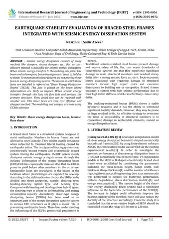
According to AISC 341 16 Provisions, ISMB 175 I Section is used as the link beam. Section dimensionsof 175mmI Sectionisgiveninthebelowfigure.
Fig-1: Sectiondimensionsof175mmI Section
Analysis results obtained by using I Section 175 mmis giveninthetablebelow.
SB I section 175 mm
4 73.93 0.0036 4 77.142 0.0037
TABLE 1: Displacementanddriftsofvariousstoriesof LinkbeamIsectionof175mmsize. 93 76 3 62.852 00057 33 3 65.815 00060 45 2 45654 0.0072 15 2 4768 0.0075 15 1 24008 00080 03 1 25134 00083 78 0 0 0 0 0 0
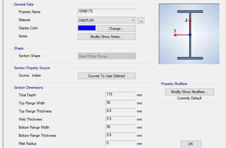
ISMB175Boxsectionisusedasthelinkbeam. The followingtablegivestheanalysisresults.
Volume: 09 Issue: 07 | July 2022 www.irjet.net p ISSN: 2395 0072 © 2022, IRJET | Impact Factor value: 7.529 | ISO 9001:2008 Certified Journal | Page712
FIG-2: Sectiondimensionsof175mmBox-Section
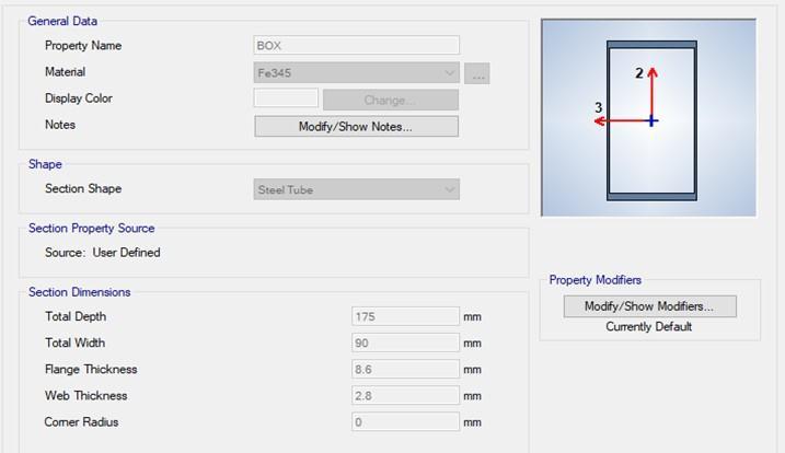
thicknessis9.8 mm so as to attain the same area as that of I-Section link beamandboxsectionlinkbeam. 8 14 2 46.512 0.0073 78 2 49.76 0.0079 34 1 24.377 0.0081 26 1 25.957 0.0086 52 0 0 0 0 0 0
Fromaboveresults,itisclearthatLinkBeamofI-SECTION is more effective as it has comparatively less displacement(73.93 mm)than Box section and Circle section link beam.(displ=75.509 mm).The base shear for allofthosesectionfoundtobealmostequal,but thereisa smalldecreaseincaseofI-Sectionlinkbeam.
4. ANALYSIS OF I-SECTION LINK BEAM OF
SIZE 200 mm
ThischapterdealswiththeanalysisofI-Sectionlinkbeam of size 200 mm in 2 different patterns; in forwardpattern andbacktobackpattern.
FIG-4: 3DView
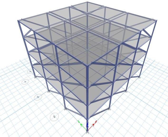
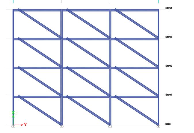
FIG-5: Elevation
International Research Journal of Engineering and Technology (IRJET) e-ISSN: 2395-0056
Volume: 09 Issue: 07 | July 2022 www.irjet.net p-ISSN: 2395-0072 200 mminbacktobackpattern.
SB I section 200 mm (in forward pattern)
THX THY STO RY NO
DISPLACEM ENT DRIFT STO RY NO
DISPLACEM ENT DRIFT 4 72822 00036 4 77183 00037 29 81 3 61.936 00056 3 65.841 00060 32 44 2 45.039 00071 2 47.708 00075 01 13 1 23736 00079 1 2517 00083 12 9 0 0 0 0 0 0
Thefollowingfiguresshows3Dviewandelevationofasteel buildingwithI Sectionlinkbeamofsize200mminbackto backpattern.
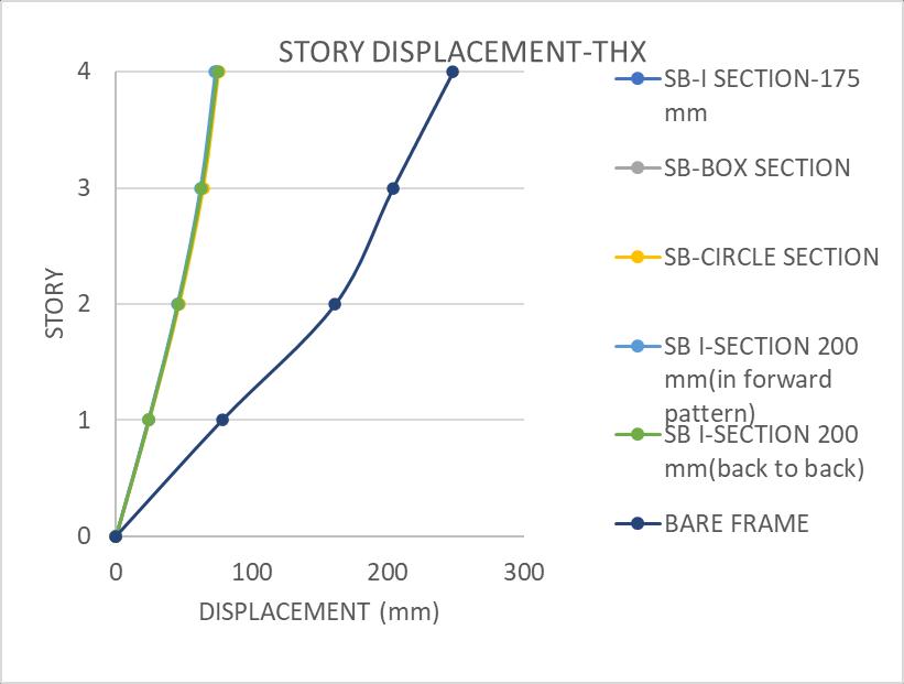
TABLE-5: DisplacementandstorydriftofSBI-Section
SB I section 200 mm (back to back)
THX THY STO RY NO DISPLACEM ENT DRIFT STO RY NO DISPLACEM ENT DRIFT
4 74804 0.0040 85 4 84321 0.0042 89 3 63.24 00059 7 3 72.254 00067 04 2 45882 00072 67 2 52702 00084 1 1 2424 0.0080 8 1 27572 0.0091 91 0 0 0 0 0 0
LinkBeamI-Sectionofsize200mm(inforwardpattern)is more effective than 175 mm size. Displacement, Drift and Base shear of 200 mm is less compared to 175 mm ISection.So,We take I-section of200 mm size as link beam forfurthercomparativestudies.
The story displacement variations and story drift variations in x and y directions of different pattern comparedwithbareframeisgivenbelow:
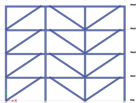
FIG 6: 3DView
TABLE-4: DisplacementandstorydriftofSBI-Section200 mminforwardpattern. FIG-7: Elevation © 2022, IRJET | Impact Factor value: 7.529 | ISO 9001:2008 Certified Journal | Page714
FIG-8: Storydisplacementinxdirection
International Research Journal of Engineering and Technology (IRJET) e-ISSN: 2395-0056
Volume: 09 Issue: 07 | July 2022 www.irjet.net p-ISSN: 2395-0072
STORY
SB I SECTION 200 mm(in pattern)
5. ANALYSIS OF SB WITH ENERGY DISSIPATING BEAMS ON DIFFERENTLOCATIONS
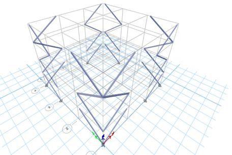
This chapter deals with the analysis of steel buildingwith energy dissipating system on different locations.For this studyweselectedbracingsplacedonalternatebasessinceit foundtobecomparativelyeffective.Thedifferentlocations include interior, exterior, interior middle, exterior middle, Xshape,diagonal.
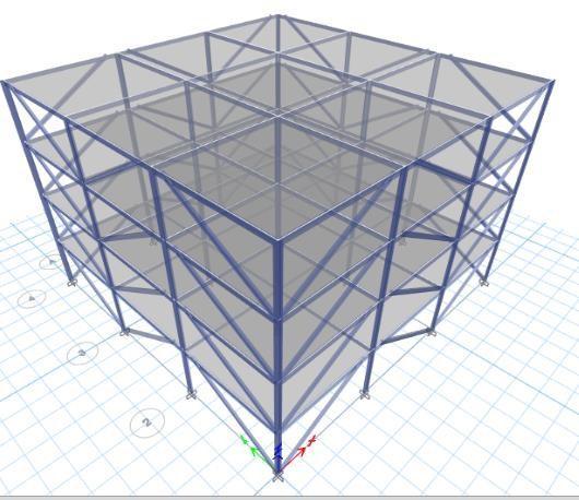
FIG-12: 4S-alternatebase-exterior
FIG-13: 4S-alternatebase-exterior
International Research Journal of Engineering and Technology (IRJET) e-ISSN: 2395-0056
Volume: 09 Issue: 07 | July 2022 www.irjet.net p-ISSN: 2395-0072
Table-6:comparisonofDisplacement,drift,baseshear
and timeperiodoflinkbeamsondifferentlocations.
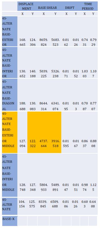
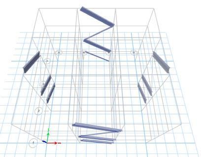
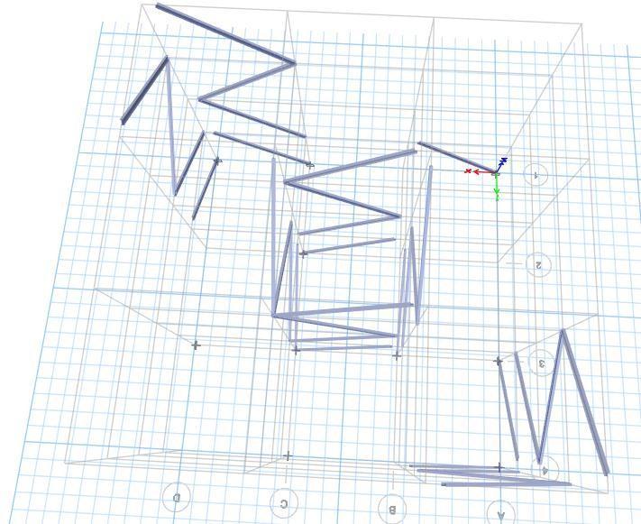
FIG 14: 4S alternatebase interiormiddle
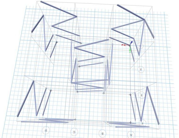
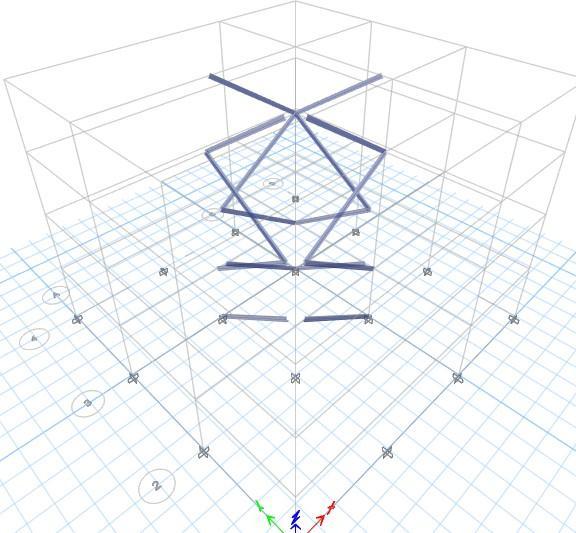
FIG 15: 4S alternatebase diagonal
FIG 16: 4S alternatebase XShape
International Research Journal of Engineering and Technology (IRJET) e-ISSN: 2395-0056
Volume: 09 Issue: 07 | July 2022 www.irjet.net p-ISSN: 2395-0072
Among the EDB’s placed on interior, exterior, interior middle, exterior middle, diagonally Shaped, EDB placedon exterior middle is found to be more seismically effective. Since its displacement in X direction is
127.094 mm and displacement in Y direction is 122.322 mm, base shear in X and Y directions are 4737.644and3916.518KNrespectively.Similarlydriftand timeperiodisalsolesscomparedtootherlocations.
This comparative study is conducted by introducing energy dissipation beam (EDB) on steel building to effectively concentrate the shear forces on the link beam only.Thus,protectingthemainstructuralcomponentsina steel building from seismic hazards. Among different sections usedforlink beam,I-Sectionis the most effective section.
7. CONCLUSIONS
6.
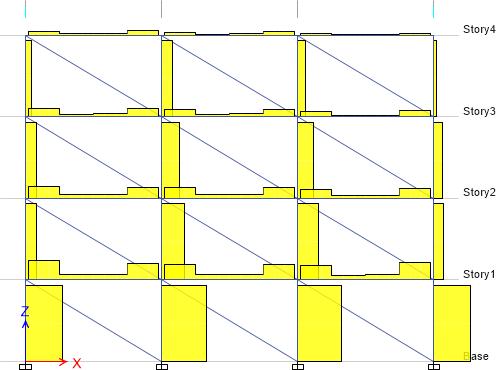
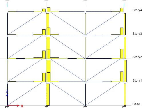
SHEAR FORCE DISTRIBUTION ON STEEL BUILDING WITHOUT EDB AND WITH EDB.
Shear forcedistributionof steel building withandwithout EDBfiguresisgivenbelow.
From the analysis of different SEDB models following conclusionscanbedrawn:
1. I-Section link beam have comparatively less displacement (73.93 mmin X-axis,77.141 mmalongy axis),lessbaseshear (around10000KN alongxand y directions)andlessdrift.
2. By selecting I-Section link beam, various sizes for ISectionsay175mmand200mmisanalysed.
3. Among 175 mm and 200 mm I-Section ,200 mm ISectionperformedwell.
4. I-Sectionof200mmisarrangedin2configurations;in forwardpatternandbacktobackpattern.Outofthese2 patterns, Link Beam I- Section of size 200 mm (in forward pattern) is more effective than 175 mm size sinceitsdisplacement,driftetc.areless.
FIG
17: SBwithoutEDB
FIG-18: SBwithEDB
5. It has 72.822 mm displacement in x direction,77.183 mm displacement in y direction, around 10160 KN base shear on x and y direction,0.008 driftonx andy directions.
6. Among theEDB’s placed on interior, exterior,interior middle, exterior middle, diagonally, X Shaped, EDB placed on exterior middle is found tobe moreseismicallyeffective.
7. Since its displacement in X direction is 127.094 mm displacementinYdirectionis 122.322mm
8. Base shear in X and Y directions are 4737.644 and 3916.518KNrespectively.
9. Least base shear results in least stiffness, hence greaterflexibilityofthebuilding.
10. steel buildingsinstalledwithenergydissipation beam (shear fuse) concentrate the shear force distribution onEDBitself.
11. Thus, the damage is mostly concentrated on EDB instead of beams and columns and the fuse can be replacedwhenfailed.
International Research Journal of Engineering and Technology (IRJET) e-ISSN: 2395-0056
12. Repairing of structural members can be reduced toa greaterextent.
REFERENCES
[1]. Jixiang Xu et.al “Seismic performance of shear energy dissipation beams in D shaped eccentrically braced steel frames”Journal of Constructional Steel Research,2021.
[2]. Yan Wen Li, Yuan Zuo Wang, Yan Bo Wang “Experimental and numerical study of beam through energy dissipative rocking columns for mitigating seismic responses”Journal of constructional steel research,2021
[3]. Feifei Shao, Miki Taguchi “Experimental study on damage detectable brace type shear fuses”Engineering structures,2020
[4] Alper Kanyilmaz, Milot Muhaxheri, Carlo Andrea Castiglioni“Influenceofrepairablebeamsplices(structural fuses)onreducingtheseismicvulnerabilityofsteel concrete composite frames”. Soil dynamics and earth quake engineering, 2019 https: //sci hub.se/10.1016/j.jcsr.2016.03.019
[5] Yiyi chen and Ki Ki “the seismic performance of high strength steel frame equipped with sacrificialbeams of non compactsectionsinenergydissipationbays”,2019
Volume: 09 Issue: 07 | July 2022 www.irjet.net p-ISSN: 2395-0072 © 2022, IRJET | Impact Factor value: 7.529 | ISO 9001:2008 Certified Journal |