International Research Journal of Engineering and Technology (IRJET) e-ISSN: 2395-0056

Volume: 09 Issue: 07 | July 2022 www.irjet.net p-ISSN: 2395-0072
International Research Journal of Engineering and Technology (IRJET) e-ISSN: 2395-0056
Volume: 09 Issue: 07 | July 2022 www.irjet.net p-ISSN: 2395-0072
1.Harshal S. Hemane, 2. Raman Iyer, 3. Ashish Kumar Mishra, 4. Aditi Sangar
1 Assistant Professor, Bharati Vidyapeeth (Deemed to be University) College of Engineering,Pune 2,3,4 Student, Bharati Vidyapeeth (Deemed to be University) College of Engineering,Pune ***
Abstract- The disabled person gets the most from hand operated vehicles since they can move in the direction, they wish to go without having to punch any buttons. This system includes a glove with a receiver circuit mounted on top and an Atmega microcontroller connected to an accelerometer that the user is expected to wear while operating the device. RF receiver, Arduino micro, Raspberry pi Pico, and Driver IC are all components of the vehicle's circuit. The Arduino mini transmits the orders that are received by the IC on the circuit to the RF receiver, which then sends the signal to the motor driver, driving the motors in turn.
Keywords raspberry pi Pico, RF receiver, automatic vehicleatmega328,RFtransmitter,DCmotor
Everything in today's world is automated, and artificial intelligence has taken over the market. One of the key components of innovation is robotics. Artificial intelligenceandroboticsareunrelatedbutdistinctfields. Robotics is the process of building machines that can carry out activities without human assistance, whereas AIisthe processthrough whichmachines mimic human decision making and learning. Although robotics can have an AI component (and vice versa), both can exist independently of one another and typically do. Most simple, repetitive task performing robots don't require sophisticated AI because their jobs are straightforward, predictable,andpre programmed.
However, many of these AI free robotics systems were developedkeepinginmindthepastlimitationsofAI,and as the technology continues to advance at a breakneck pace every year, robotics manufacturers may feel more confident in pushing the boundaries of what is possible whencombiningthetwodisciplines.
A robot is a machine that can automatically complete a complex series of tasks, especially one that can be programmed by a computer. A robot can be directed by aninternal control systemoranexternal control device. Although some robots are built to resemble humans, most robots are task performing machines that place a greater focus on bare utility than on expressive aesthetics.
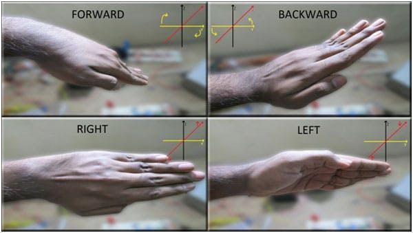
A robot that can be controlled by gestures rather than conventional buttons is known as a gesture controlled robot. You merely need to carry a little transmitting devicewithanaccelerationmetreinyourhand.Thiswill send therobotthe appropriateinstruction sothat itcan performwhatevertaskweaskofit.
Robot controlled by gestures moves as our hands develop as we hold the transmitter in our hands. Robot starts moving forward when we turn toward the front and continues moving forward until the next command is delivered. Robot changes state and starts moving in reversedirectionwhenhandistiltedtotheoppositeside until another command is provided. When we turn it to the left Robot moves left and in the following direction. Robot rotated to the right when we inserted our hands. Additionally, in order to halt the robot, we maintain stablehand.
The main goal of this project is to use an accelerometer and a Raspberry Pi Pico to control the evolution of the robotwithhandgestures.Typically,arobotisamachine thatoperatesautonomouslythroughhandmotions.
Since a long time ago, robotic vehicles have been operated by hand gestures in both the transform and spatial domains. In this section, a few techniques have beenexamined.
NitinGargandChiragGupta haveproposeda method.A gesture controlled robot, or "gesture controlled car," is onethatmaybeoperatedwithhandgesturesratherthan themoretraditionalwayofpressingbuttons.Simplyput, the user must wear a tiny transmitting gadget with an accelerometer type sensor on his hand. An extremely precise hand movement can send an instruction to the robot,whichcanthenmoveinthatexactsamedirection. The transmitting device has an encoder IC for encoding thefour bitdatasothatitcanbecommunicatedbyanRF transmitter,aswellasacomparatorICforallocatingthe proper levels to the input voltages from the accelerometer.
Itisfeasibletomovea robotinaccordancewithgesture detection, according to a technology developed by Archika et al.1 that uses an accelerometer sensor. The
International Research Journal of Engineering and Technology (IRJET) e-ISSN: 2395-0056
Volume: 09 Issue: 07 | July 2022 www.irjet.net p ISSN: 2395 0072
primary technologies for interacting between humans and machines, accelerometers provide extremely decent motion sensitivity in a variety of applications. Motion technology makes it easier for people to interact organically with machines without the need for modifications brought on by mechanical equipment' shortcomings. Its low moderate cost and the relatively modestsizeoftheaccelerometersarethecharacteristics that make it an excellent tool to detect and understand humangestures.
The Hand Gesture Controlled Robot Using Arduino was presented by Ms. Asmita Jadhav. This paper introduces an Arduino based Hand Gesture Controlled Robot that can be operated with a single hand gesture. The accelerometer starts moving in response to a person's hand movement. Based on three accelerometer axis, the robot can move in four directions: left, right, forward, and backward. We employ an infrared sensor with a 790nm wavelength range to detect human movements. This kind of robot is frequently employed in industrial robotics, the construction industry, and military applications. In such a field, it is extremely dangerous and challenging to operate the machines using switches or remotes, and occasionally an operator may become confused as a result. This novel concept brings machine controlthroughhandmotion.
Human computerinteraction(HCI)isbecomingthemost importanttopicforresearchersandscientists,according to Soubagya Nayak, as a result of the relentless juggernaut of computing advancements and artificial intelligence creeping into our lives. However, the traditionalHCIapproachofusingamouseandkeyboard makes life boring and stifling. In order to improve the qualityoflifefortheelderlyandphysicallydisabled,itis imperativethatgesturecontroltechnologybeimproved. Our research moves forward with the lofty goal of creating a modernized environment for HCI by eliminating all the undesirable, antiquated, traditional communicating peripherals like the keyboard and mouse. It illustrates the use of a 3 axis accelerometer sensorandhandgesturecontroltooperatearobot.
Thelistofcomponentsused:
3.1 Battery: An electricalbatteryismadeupofoneor more electrochemical cells that work together to transform chemical energy that has been stored away into electrical energy. For many domestic and commercial uses, batteries are now a standard powersource.
3.2 Voltage Regulator: The three terminal positive regulators of the LM78XX/LM78XXA series come in
the10 220/D PAKpackageandincludeanumberof set output voltages, making them useful in a variety of applications. Internal current limiting, thermal shutdown,andsafeoperatingareaprotectionareall used by each kind, making them virtually indestructible. They can deliver more than 1A of outputcurrentifsufficientheatsinkingisoffered
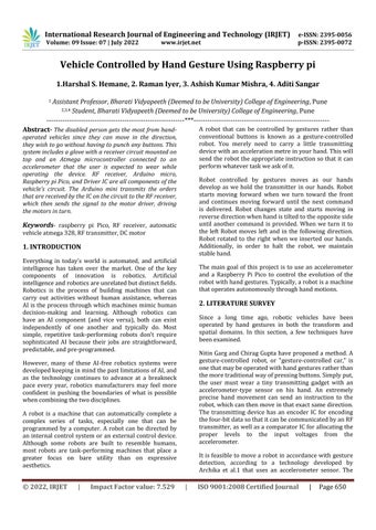
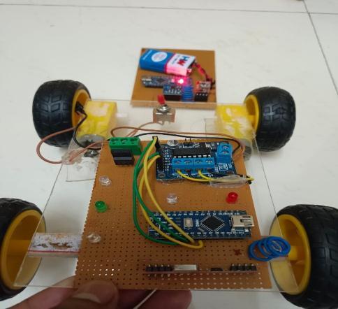
3.3 Raspberry pi: - Thesystemonchip(SOC)boardfor the Raspberry Pi is manufactured by Broadcom (BCM2835). It has an ARM1176JZF S core CPU, 256 MB of SDRAM, and a clock speed of 700 MHz The Raspberry
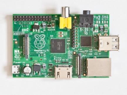
Fig 1: Raspberrypi
Pi USB 2.0 ports only support external data communication. The micro USB adaptor, with a minimum range of 2. Watts, provides power for the board (500 MA). The purpose of the graphics specific chip is to accelerate the processing of picture calculations. This has a Broadcom video core IV wire builtintoit.
3.4 Push buttons: Push buttons can be mechanically linked together in industrial and commercial applicationssothatpressingonebuttonreleasesthe other, allowing a stop button to "compel" a start button to release. When a machine or process does not include electrical control circuitry, this form of linking is employed for straightforward manual actions.Inordertopreventoperatorsfrompressing the incorrect button, pushbuttons are frequently color codedtocorrespondwiththeirfunctions.
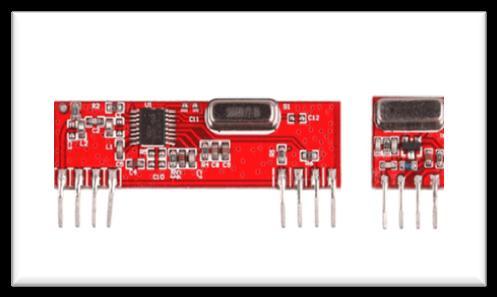
3.5 Motor Driver: Two integrated H bridge driver circuitsarepresentinL293D.TwoDCmotorscanbe run concurrently in both forward and reverse directions in its usual mode of operation. The input logicatpins2&7and10&15cancontrolthemotor operations of two motors. The matching motor will stop if input logic is 00 or 11. It will rotate counterclockwiseforlogic01andclockwiseforlogic 10, accordingly. The two motors' respective enable pins I and 9 must be high for the motors to begin running. The linked driver is enabled when an
International Research Journal of Engineering and Technology (IRJET) e-ISSN: 2395-0056
Volume: 09 Issue: 07 | July 2022 www.irjet.net p ISSN: 2395 0072
enableinputissettohigh.Theoutputsthusbecome active and operate in synchrony with their inputs. Similarly, that driver is disabled and their outputs arenotactivewhentheenableinputislow
3.6 DC motor: - Axle, rotor (also known as armature), stator, commutator, field magnets, and brushes are the six fundamental components of a DC motor. High strength permanent magnets are used to providetheexternalmagneticfieldinthemajorityof typical DC motors. The motor's stationary component, known as the stator, consists of the motor casing and one or more permanent magnet pole pieces. In relation to the stator, the rotor revolves. The commutator is electrically coupled to the windings that make up the rotor, which are typically on a core. When power is provided, the activated winding and the stator magnet(s) are mismatched due to the geometry of the brushes, commutator contacts, and rotor windings. As a result, the rotor rotates until it is almost aligned withthestator'sfieldmagnets.Thebrushesadvance to the following commutator contacts as the rotor aligns and energize the following winding. With regard to our two pole example motor, spinning causes the current flowing through the rotor winding to reverse direction, causing the magnetic field of the rotor to "dip," which causes the rotor to continuerotating.
3.7 RF Transmitter: The best option for wireless control applications needing short range and good quality is this PLL based ASK Hybrid 434 MHz RF transmitter module. A SAW stabilized oscillator is used in the transmitter module to ensure precise frequency control for optimal performance over the broadest feasible range. The transmitter's 3 to 12 volt power source range makes it ideal for battery poweredapplications.
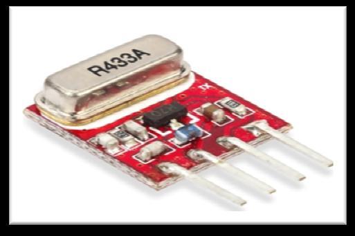
3.8 RF Receiver: The modulated RF signal is fed into anRFreceivermodule,whichdemodulatesit.Super regenerative receivers and super heterodyne receivers are the two different types of RF receiver modules. Super regenerative modules often employ a series of amplifiers to separate modulated data fromacarrierwaveinlowpower,low costdesigns.
Fig-4: RFReceiver
3.8 Diodes: The highest reverse bias voltage capacity of diodes with the numbers IN4001, IN4002, IN4003, IN4004, IN4005, IN4006, and IN4007 is 50V,whilethemaximumforwardcurrentcapacityis 1 Amp. Similar capacity diodes can be substituted for one another. In addition, a diode with a higher capacitycanbeusedinplaceofadiodewithalower capacity,butthereverseisnottrue.
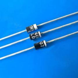
Fig-5: Diodes
3.9 Accelerometer: - The user can better grasp an object's surrounds thanks to accelerometers. This little device lets you tell whether anything is flying horizontallyoranglingdownward,whetheritwould
International Research Journal of Engineering and Technology (IRJET) e-ISSN: 2395-0056
Volume: 09 Issue: 07 | July 2022 www.irjet.net p ISSN: 2395 0072
topple over if it tilts any farther, and whether it is travelling uphill. The most popular type of accelerometer uses the piezoelectric effect, which relies on small crystal formations that are strained byaccelerationforces.Thetensiononthesecrystals generates a signal, which the accelerometer interprets to calculate velocity. and direction. The capacitance accelerometer detects changes in capacitance between nearby microstructures. When one of these structures is moved by an accelerative force, the capacitance will vary, and the accelerometerwillconvertthischangetovoltagefor interpretation.
We note down the range for the forward tilt we take a reading when the hand is slightly tilted and do another reading when the hand is tilted to the maximum angle. With these values of x and y, we get a range for x and a rangefory.
Similarly,wetakethereadingforthebackwardtiltofthe hand,right,left,andstationarytiltofthehand.
After noting down the range of x and y in forwarding, backward,left,right,andstationarypositionsofhandwe move to coding the final code using micro python in thonnyide.Westartbyincludingthevirtualwirelibrary which is necessary for transmitting and receiving any messagethroughtherftransmitterandreceivermodule. 3integersaredefinedheretwoforxandyvalueswhich are analog values and one integer as led13 which is the inbuilt led. We set pin13 as output. In the void loop, we start by assigning the x value and y value sent by the adxl335accelerometertothex valueandy value.
Fig 6: Accelerometer
ThetransmitterpartofthisprojectcontainsaRaspberry pi pico and adxl335 accelerometer and RF receiver module.
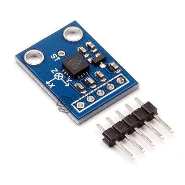
The adxl335 accelerometer provides output in the form of coordinates and we can read the output sent by the accelerometer. ADXL335 has the ability to provide the co ordinated in x, y, and z direction. But since we don't needthez axisvalueswedon’tconnectittotheArduino.
The purpose of the transmitter is to calculate the directionthehandhasbeentiltedandsendamessageto thereceivercorresponding toit.Thex andy axisvalues canbeinterpretedtoprovidethetiltdirectiontocontrol themotorspin.
The x and y axis pin of the adxl335 provides an analog output because of which they are connected to the analogpinsofthePi.
Inside the while loop, we set the x value and y value as integers and store the x axis value and y axis value receivedfromtheadxl335accelerometerinit.
The stored value in the integer is then displayed on the serialmonitorandaftera2 seconddelay,itdisplaysthe newx axisvalueandnewy axisvalue.
Next by using if else statements we write that if the x value and y value fall under the range (xval>395 && xval<416) && (yval>360 && yval<380) then the hand is tiltedforwardandthetransmittermodulesendsaletter “f” to the receiver, similarly for backward right left stationaryletters“a”“r”“l””s” aresentrespectively,and every time a signal is sent for forward backward left righttheinbuiltledatpin13isturnedon.
The transmitter section sends the corresponding letter to the receiver after determining whether the hand is tilted backward, left right, or stationary. Before the receivercanusethiscodeanddecodeit,weneedtogeta fewmorereadings.
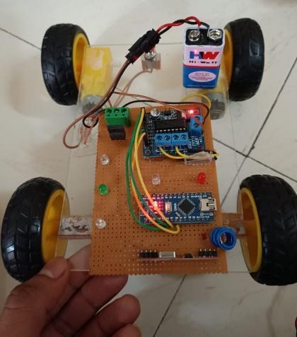
The receiver section of this project consists of an l293d motor driver 2 motors an rf receiver module and a switch.
L293DisamotordriverICwhichisusefulwhenwewish to control the direction of the motor spin without disconnecting the motor and switching the polarities. TheICpinouthasbeenattachedwhitthispaper.Wecan see that the IC has 2 enable pins. Whenever these pins aremadehighonlythendotheyallowforthatsideofthe IC to be enabled. The IC has 4 input pins and 4 output pins. Output one and output two are connected to the two terminals of the battery and outputs 3 and 4 are connected to the two terminals of another motor. The input 1,2,3, and 4 are connected to Arduino and the Arduino gives the signal for the direction of motor spin viathesepins.wedetecthowtheinputvaluesneedtobe changedforthemotortospininthedesireddirectionby writingasimplecodeonthonnyide.
International Research Journal of Engineering and Technology (IRJET) e-ISSN: 2395-0056
Volume: 09 Issue: 07 | July 2022 www.irjet.net p ISSN: 2395 0072
Inthiscode, westart bynaming the pinsconnectingthe picowiththeIC.
Thenbydigitallywritingthevaluesofinput123and4, we note down the combination for which both motors spin forward, both the motors spin backward, one spins forwardwhiletheotherdoesn'tmove,andvice versa.By this, if we want the motor to take a right turn we know whichinputtosetashighand whichinputtosetaslow toachievethiscondition.
Afterthis,wemoveontowritingthefinalcode. Herewereceivethelettersentbythetransmittersignal. If the signal received is f then we turn the input pins of the IC as high and low for the vehicle to move forward. Similarly,itisdonebackward,left,andright.
The system's objective is to use a Raspberry Pi Pico to construct an accelerometer based hand gesture controlledcar.Simplemovementscanbeusedtomoveit in any direction, and we can successfully balance the system's responsiveness to motions to suit our preferences.
Aftercarefullystudyingthissystem,wehavecometothe conclusion that when a person moves their hand in any of the four directions Left, Right, Down, or Up the accelerometer will identify changes and send a certain signal to the next order. accelerometer raspberry pi Pico encoder transmitter decoder motor driver motor. The suggested method can be used in hazardous environments when a vehicle mounted camera can be observed by the user. This technique can alsobeusedinthemedicalindustry,wheresmallrobots have been developed to aid surgeons in performing effectivesurgeries.
The system's real time palm gesture detection feature, whichenablesintuitiveandefficientvehicleoperation,is one of its key advantages. By properly installing the sensor, the vehicle can be improved to detect people
International Research Journal of Engineering and Technology (IRJET) e-ISSN: 2395-0056 Volume: 09 Issue: 07 | July 2022 www.irjet.net p ISSN: 2395 0072
buried under earthquake and landslide debris. The vehicle can be equipped with a GPS device to track its location. The tool may alsobe utilized by the military to keep an eye on battlefield locations devoid of human activity.
1. Chan Wah NG, Surendra Ranganatha, Real time GestureRecognitionSystemandApplicationImage andVisionComputing(20):993 1007,2002.
2. Sergio’s Theodoridis, Konstantinos Koutsoubos, Pattern Recognition, Elsevier Publication, Second Edition,2003.
3. Seyyed Eghbal Ghobadi, Omar Edmond Logperch, Farid Ahmadov Jens Bernshausen, Real Time Hand Based Robot Control Using Multimodal Images, Iaengm International Journal of Computer Science,35:4,IJCS_35_4_08,Nov2008.
4. https://circuitdigest.com/microcontrollerprojects/a ccelerometer basedhand gesture controlled robotusing arduino
5. Setia Archika, Mittal Surbhi, Nigam Padmini, Singh Shalini, Gangwar Surendra "Hand gesture recognition based robot using accelerometer sensor, International Journal of Advanced Research in Electrical, Electronics and InstrumentationEngineering2015:4(5):4470 76.
6. Gupta Chirag and Gary Nitin, "Gesture controlled car,InternationalJournalofElectronics.
7. Sham sheer. "Hand gestures remote controlled robotic arm". Advance in Electronic and Electric EngineeringInternational2013,3601 06.
8. JawalekarPrajwalAshwin,"Robotcontrolbyusing human hand gestures International Research JournalofEngineeringandTechnology2018,5(2): 389 91.
9. Wu Xing Han, Su Mu Chun, and Wang Pa Chun, "A hand gesture based control interface for a car robot", Institute of Electrical and Electronics Engineers.2010;4(10):4644 648.
10. Mansuri Riyaz, Vakale Sandesh, Shinde Ashish, Patel Tanveer, "Hand gesture control robot vehicle", International Journal of Electronics & CommunicationTechnology2013,4(2):77 80.
11. Sathiyanarayanan Mithileysh, Azharuddin Syed, KumarSanthosh,KhanGibran,"Gesturecontrolled robot for military purpose", International Journal for Technological Research in Engineering 2014: 1(11):1300 303.