International Research Journal of Engineering and Technology (IRJET) e ISSN: 2395 0056

Volume: 09 Issue: 07 | July 2022 www.irjet.net p ISSN: 2395 0072
International Research Journal of Engineering and Technology (IRJET) e ISSN: 2395 0056
Volume: 09 Issue: 07 | July 2022 www.irjet.net p ISSN: 2395 0072
1Student, St. Joseph’s College of Engineering and Technology, Palai
2Assistant Profosser, St. Joseph’s College of Engineering and Technology, Palai ***
Abstract Beam column joints are the most seismically affected element in a framed structure, hence seismic performance of joint is of great importance for overall structural safety. In order to make appropriate design decisionsfor joints, itis necessarytoknowhow jointsbehave. Concrete encased concrete filled steel tubular (CFST) beam column joints consist of CFST inside and reinforced concrete outside. Several investigations have beenconductedon joints with steel beams and RC columns and with steel beams and CFST columns. This paper studies load carrying capacity of concrete encased CFST beam column joints by ANSYS software
Key Words: Beam column joints, CFST, load carrying capacity.
Theintersectionportioncommontocolumnandbeamina buildingisknownasbeamcolumnjoint.Framesthatresist moment in reinforced concrete, the joint in between the columnandbeamiscritical.Duringseveregroundshaking,it isexposedtolargeforces,anditsbehaviourhasa notable impactontheresponseofthestructure.Connectionbetween beam and column in a frame structure is most likely to sustaindamageduringaseismicdisaster.Theproperdesign andexecutionofitisnecessaryforabetterperformance.In ordertomakeappropriatedesigndecisionsforjoints,you needtoknowhowjointsbehave.Acompositeelementisa structural element that is made of two or more different materials. Composites offer the benefit of combining the propertiesofeachmaterialintooneunitthatperformsmore effectivelythanitsconstituentpartsindividually.Oneofthe mostpopularlyusedcompositemembersinthestructural engineering industry is steel concrete composite. We all know that concrete is week in tension and good in compressionalsosteelisweekincompressionandgoodin tension,bycombiningbothwecanmakeamemberwhich exhibitsbothpropertiesofconcreteandsteelandhencegive betterperformance.Beam columnjointswithconcretefilled steel tube (CFST) with concrete encasing consisting CFST inside and concrete with reinforcing outside. Steel tubes filled with concrete (CFST) have a number of structural advantages,suchasincreasedstrengthandresistancetofire attacks, as well as high ductility and energy absorption efficiency. The embedded steel tubes in such joints make themstronger, moreductile,andmoreabletocarrymore weight than ordinary concrete beam column joints.
ComparedwithordinaryCFSTmembers,thememberswith concrete encasing CFST have better fire resistance and durabilitybytheprotectionofexternalRCcomponent.Also, it shows favorable seismic behaviour and can be used in earthquake prone areas. Moreover, construction speed is increasedbecausetheCFSTcanbeconstructedinitiallyto carrythetotalconstructionloadingsandtheconcretepart andreinforcingbarsarepouredorinstalledlater.
CFSTbeam tocolumnjointwithconcreteencasingismade upofCFSTascoreandreinforcedconcrete(RC)outside.The Performanceofconcrete encasedCFSTbeam columnjoints istobeevaluatedbyfiniteelementmethodusingANSYS.
To study load carrying capacity of encased CFST beam columnjoints.
To analyze concrete encased CFST beam column jointscyclicallyusingANSYS.
TheParametricStudiestobedoneare:
EffectofconcreteencasedCFSTindifferenttypesof joints.
Effectofdifferentmixproportionsofconcrete.
Theparametersconsideredforthemodellingandanalysis ofexteriorCFSTcolumn steelbeamjointis:
• Steelbeam concreteencasedCFSTcolumnjointis considered
•
Lengthofbeam:1.75m
• Lengthofcolumn:1.5m
• Reinforcement
• Mainbar:18mm
• Middlebar:14mm
• Stirrups:8mm
• Mixproportionofconcrete:M25
International Research Journal of Engineering and Technology (IRJET) e ISSN: 2395 0056
Volume: 09 Issue: 07 | July 2022 www.irjet.net p ISSN: 2395 0072
Andmaterialpropertiesare:
ForStructuralSteel,
• Density:7850Kg/m3
• Young’smodulus:2x10⁵MPa
• Poisson’sratio:0.3
• Tensileyieldstrength:250MPa
• Tensileultimatestrength:460MPa
• Compressiveyieldstrength:250MPa

• Density:2300Kg/m3
• Young’smodulus:29250MPa
• Poisson’sratio:0.18
• compressiveultimatestrength:25MPa
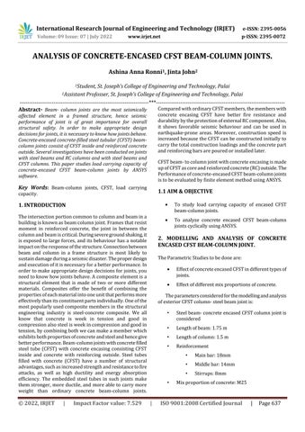
Table 1: maximumloadcarriedbyexteriorCFSTjoint.
Pmax(+)(KN) 149.09
Pmax( )(KN) 140.2
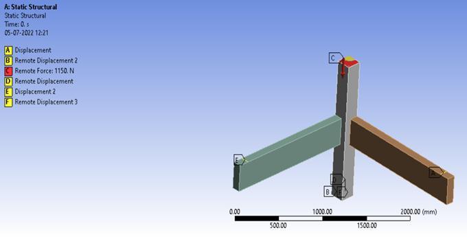
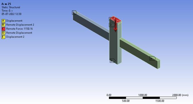
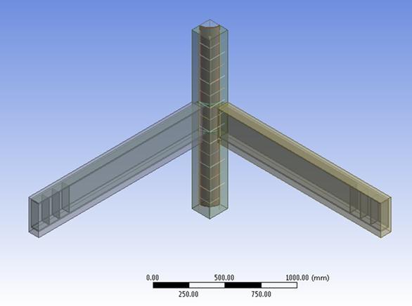
Fig 1: symmetrymodelusedforanalysisofexteriorCFST joint.
Chart 1: Hysteresisloopofexteriorjoint.
2.2 3D JOINT WITH M25 GRADE CONCRETE
• Density:2300Kg/m3
• Young’smodulus:29250MPa
• Poisson’sratio:0.18
• compressiveultimatestrength:25MPa
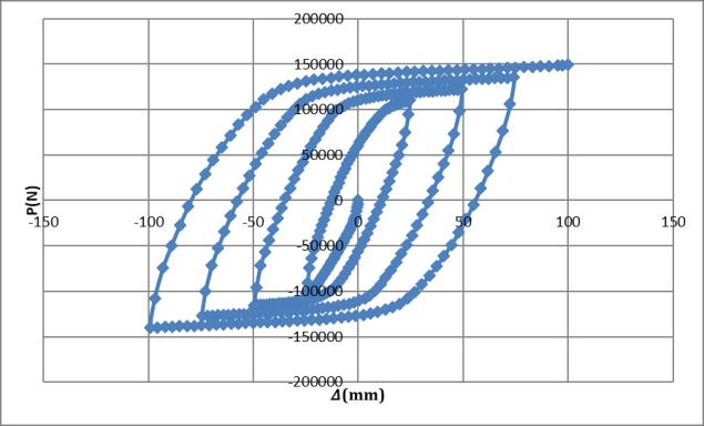
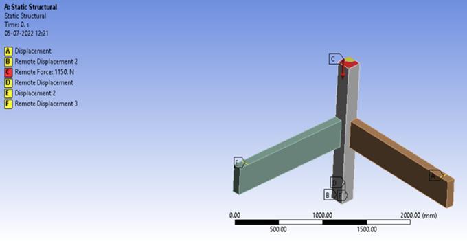
Fig 2: boundaryconditionsofexteriorCFSTjoint.

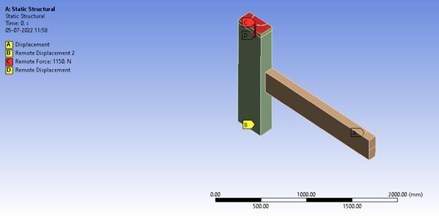
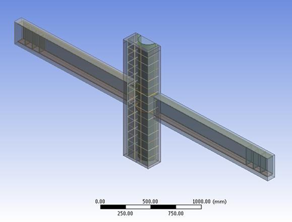
Fig 3: symmetrymodelusedforanalysisof3DCFSTjoint.
Fig-4: boundaryconditionsof3DCFSTjoint.
International Research Journal of Engineering and Technology (IRJET) e ISSN: 2395 0056
Table 2: maximumloadcarriedby3DCFSTjoint.
Pmax(+)(KN) 134.2
Pmax( )(KN) 131.7
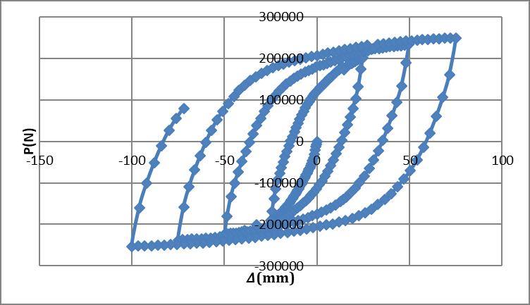
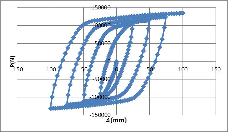

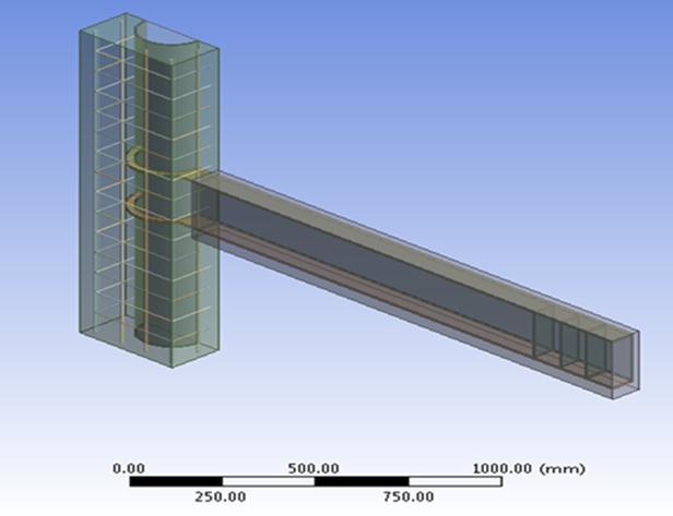
Chart 2: Hysteresisloopof3Djoint.
• Density:2300Kg/m3
• Young’smodulus:29250MPa
• Poisson’sratio:0.18
• compressiveultimatestrength:25MPa
Table 3: maximumloadcarriedbyplanarCFSTjoint.
Pmax(+)(kN) 249.4
Pmax( )(kN) 253.02
Fig 5: symmetrymodelusedforanalysisofplanarCFSTjoint.
Chart 3: Hysteresisloopofplanarjoint.
• Density:2300Kg/m3
• Young’smodulus:27117MPa
• Poisson’sratio:0.18
• compressiveultimatestrength:30MPa
Fig 6: boundaryconditionsofplanarCFSTjoint.
Fig 7: symmetrymodelusedforanalysisofexteriorCFST joint.
Fig 8: boundaryconditionsofexteriorCFSTjoint.
Volume: 09 Issue: 07 | July 2022 www.irjet.net p ISSN: 2395 0072 © 2022, IRJET | Impact Factor value: 7.529 | ISO 9001:2008 Certified Journal | Page639
International Research Journal of Engineering and Technology (IRJET) e ISSN: 2395 0056
Volume: 09 Issue: 07 | July 2022 www.irjet.net p ISSN: 2395 0072
Table 4: maximumloadcarriedbyexteriorCFSTjoint.
Pmax(+)(KN) 162.78
Pmax( )(KN) 153.15
Table 5: maximumloadcarriedby3DCFSTjoint.
Pmax(+)(KN) 146.1 Pmax( )(KN) 143.8
Chart 4: Hysteresisloopofexteriorjoint.

• Density:2300Kg/m3
• Young’smodulus:27117MPa
• Poisson’sratio:0.18
• compressiveultimatestrength:30MPa
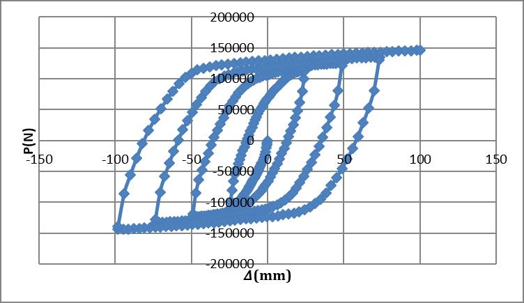
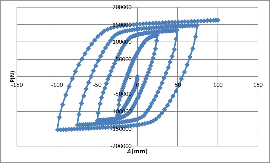
Fig 10: boundaryconditionsof3DCFSTjoint.
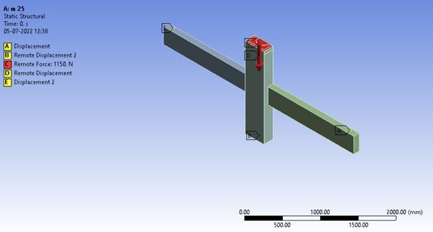
Chart-5: Hysteresisloopof3Djoint.
• Density:2300Kg/m3
• Young’smodulus:27117MPa
• Poisson’sratio:0.18
• compressiveultimatestrength:30MPa
Fig 11: symmetrymodelusedforanalysisofplanarCFST joint.
Fig 12: boundaryconditionsofexteriorCFSTjoint.
International Research Journal of Engineering and Technology (IRJET) e ISSN: 2395 0056
Table 6: maximumloadcarriedbyplanarCFSTjoint.
Pmax(+)(KN) 275.1 Pmax( )(KN) 262.29 Chart-6: Hysteresisloopofplanarjoint.
The obtained results for concrete encased beam column jointsareasfollows:
Pmax (+) (kN) Pmax ( ) (kN)
Exteriorjoint M25 149.09 140.2 M30 162.78 153.15
3Djoint M25 134.2 131.7 M30 146.1 143.8
Planarjoint M25 249.4 253.02 M30 275.1 262.29
Theconcreteencasedbeam columnjointsshowbetterload carrying capacity. The embedded steel tubes in concrete encased CFST beam column joints make them stronger, more ductile, and more able to carry more weight than ordinary concrete beam column joints. Compared with conventional CFST members, the concrete encased CFST memberhavebetterdurabilityandhigherfireresistancedue totheprotectionofexternalRCcomponent.Henceitcanbe usedfortheconstructionofhigh risebuildingsandbuildings inhighlyseismicproneareas.
[1] Wei Li, Li Feng Xu and Wei Wu Qian, “Seismic performance of 3 D steel beam to concrete encased CFSTcolumnjoints:Tests”,2021
[2] Wei Li, Li Feng Xu and Wei Wu Qian, “Seismic performanceofconcrete encasedCFSTcolumntosteel beamjointswithdifferentconnectiondetails”,2022
[3] Ben Mou, Yingze Li and Qiyun Qiao, “Connection behavior of CFST column to beam joint implanted by steelrebarsundercyclicloading”,2021.
[4] ZhangD,GaoSandGongJ,“Seismicbehaviourofsteel beamtocircularCFSTcolumnassemblieswithexternal diaphragms”,2012.
[5] Fei YuLiao,Lin HaiHanandZhongTao,“Behaviourof compositejointswithconcreteencasedCFSTcolumns undercyclicloading:Experiments”,2014.
[6] Wanqian Wang, Jingfeng Wang, Lei Guo, Xiang Guo, XiaoxianLiu,“Behaviorandanalyticalinvestigationof assembledconnectionbetweensteelbeamandconcrete encasedCFSTcolumn”,2020.
[7] Yu Feng An, Lin Hai Han and Charles Roeder, “Performance of concrete encased CFST box stub columnsunderaxialcompression”,2015.
[8] K.B.ManikandanandC.Umarani,“Understandingson the Performance of Concrete Filled Steel Tube with DifferentKindsofConcreteInfill”,2021.
Volume: 09 Issue: 07 | July 2022 www.irjet.net p ISSN: 2395 0072 © 2022, IRJET | Impact Factor value: 7.529 | ISO 9001:2008 Certified Journal | Page641