International Research Journal of Engineering and Technology (IRJET) e ISSN: 2395 0056

Volume: 09 Issue: 07 | July 2022 www.irjet.net p ISSN: 2395 0072
International Research Journal of Engineering and Technology (IRJET) e ISSN: 2395 0056
Volume: 09 Issue: 07 | July 2022 www.irjet.net p ISSN: 2395 0072
PG Student, Department of Electrical Engineering, Government College of Engineering, Karad, India Associate Professor, Department of Electrical Engineering, Government College of Engineering, Karad, India ***
Abstract - Transformers are widely in the transmission network to either step up or step down the voltage. In order to get efficient performance, these transformers should be tested periodically over the period of time, whether the transformer is working in proper condition or not. For testing of the power transformers. There are various tests are conducted such as ratio test, vector group test, core balance test, no load test, short circuit test as well as load test. To perform each test there are large numbers of instruments and equipment are used. From which, each reading should be noted manually, which wastes more amount of time. To avoid those problems and to reduce human efforts, this paper represents a MATLAB SIMULINK model which can be used to perform several tests where the results are obtained in a simpler manner.
Key Words: Transformers, MATLAB SIMULINK, Tests, Performance, Accuracy
Transformer,devicethattransferselectricenergyfromonealternating currentcircuittooneormoreothercircuits, eitherincreasingi.e.,steppinguporreducingi.e.,steppingdownthevoltagesuppliedtoit.Transformersareemployedfor widelyvaryingpurposes;e.g.,toreducethevoltageoftheconventionalpowercircuits,tooperatethelow voltagedevicessuch asdoorbellsandtoyelectrictrains,toraisethevoltagefromelectricgeneratorssothatelectricpowercanbetransmittedover longdistancesetc.Comingtothiswiderangeofapplicationsoftransformers,transformerisalsorequiredtobemonitoredover the period of time for the satisfactory operations. In order to get this, we perform various performance tests on the transformers.Thesetestsaretimeconsumingaswellascancausevariouserrorssuchasconnectionerror,calculationerror, testingerror,etc.So,toavoidthis,wecanperformthesetestsonMATLAB
A. NY Dahlan, 2017 IEEE 9th International Conference on Engineering Education, Transformer Interactive Learning Tool Based on MATLAB Simulink and GUI.
ThispaperpresentstransformerinteractivelearningtoolwhichisdevelopedinMATLABSimulinkandGraphicalinterfacei.e., GUI.Thistoolisdevelopedtoimprovestudent’sinterestandunderstandingontransformersubjectandpractical.Thetool consistsofthreesectionswhicharenothingbutthetransformerperformance,open circuittestandshortcircuittest.Usingthis tool, the transformer electrical behavior can be understood and also the effect of parameter variation of transformer is observed because it is repeated several times. The output of this tool has been verified and compared with the manual calculationinlab.Thedevelopedtoolisadditionallytestedforvariousreadings
B. Amangaldi Koochaki, Indian Journal of Science and Technology, Teaching Calculation of Transformer Equivalent Circuit Parameters using MATLAB/Simulink.
ThispaperpresentsMATLAB/Simulinkimplementationoftransformertestsnamelydctest,open-circuittestandshortcircuit tests performed to identify the equivalent circuit parameters and to study effective transformer modeling and reinforcementofthetheoreticalconcepts.Theproposedmethodhasbeensuccessfullyintegratedintoelectricmachinery courses at Author University with encouraging results. The results show that relative errors are negligible, and the proposedsimulationmodelscanaccuratelypredictequivalentcircuitparameters.Also,thismethodwillbeveryhelpful forstudentswhentheycarryouthardwarelaboratoryexperimentsinpractice.
International Research Journal of Engineering and Technology (IRJET) e ISSN: 2395 0056
Volume: 09 Issue: 07 | July 2022 www.irjet.net p ISSN: 2395 0072
C. Prof. J. H. Patil, IJIRST International Journal for Innovative Research in Science & Technology Transformer Testing and Analysis using MATLAB/Simuink.
ThisresearchpapergivesinformationaboutaMATLABbasedprogramwhichutilizesaGraphicalUserInterface(GUI)to calculatethecircuitparametersandefficiencyofsingle phaseactransformer.Theprojecthasbeendesignedanddeveloped with the help of MATLAB SIMULINK. The GUI developed can be used in the form of simulation for an electrical software applicationinlabsessionforbetterunderstanding.ThispaperhaspresentedavirtualinstrumentofACtransformerwiththe helpofMATLAB&SIMULINK.Itisauser friendlyapplicationinwhichauserjustneedstogiveadesireddataforprocessing stageandoutputperformanceresult.Also,theMATLAB&SIMULINKresulthavebeenverifiedandcomparedwithmanual calculationinordertoensurethatthecorrectandreliablesolutionsareobtained.
D. Mr. M. Subramani, International Journal of Advanced Science and Engineering Research, Investigations of Power Transformer Parameters Using Core Balance and Vector Group Test.
Power transformers are used in the high voltage transmission network to step up or step down the voltage as per our requirement. These transformers should be tested periodically in order to check whether the transformer is working in optimumconditionsornot.Thispaperprovidesacomputer basedsolutionforthesetests.Toperformeachtesttherearelarge numbersofmetersandequipmentarerequired.Also,eachreadingofmeasurementshouldbenotedmanuallywhichwastes moreamountoftime.Toavoidtheseproblemstestingkitisusedwherethereadingsareindigitalformatandcommunication isalsoenabled.
Inordertoreducehumaneffortsaswellastogetincreasedaccuracy,setoftestssuchas,loadtest,opencircuittest,shortcircuit testsareperformedontransformerinMATLABSIMULINKmodel.
Overtheyears,weuseseveralsetsof equipment’sforthemeasurementofperformancetestsinMATLAB.Inrecentyears, variousresearchpaperisbeingproducedtoavoidcomplexityandperformthesetestsonMATLAB.Ourresearchpaperalso helpsinperformingthesetestswithhigheraccuracyandeasiersolutions.Althoughtheseconventionaltechniquesaregoodfor conceptual understanding but it requires human efforts. In order to get those required parameters to be calculated automatically,thispaperhelpsinprovidingMATLABsolutionoverhere.
Inordertoperformtheinternalparametercalculations,MATLABR2020aisused.TogetelectricalcomponentsinMATLAB, MATLABSimulinkaswellasSimscapelibrariesareused.
R1:InternalresistanceofTransformerfromprimaryside.
L1:Inductanceofprimaryside.
Rm:Magnetizationresistance
Poc:Opencircuitpower.
Ioc:Opencircuitcurrent.
Roc:Opencircuitresistance.
Xoc:Opencircuitreactance.
Iω:Corelosscomponent.
Vsc=Shortcircuitvoltage.
R2:InternalresistanceofTransformerfromsecondaryside.
L2:Inductanceofsecondaryside.
Lm:magnetizationinductance.
Voc:Opencircuitvoltage.
Φoc:Opencircuitpowerfactorangle.
Zoc:Opencircuitimpedance.
Iµ:Magnetizingcurrentcomponent.
Psc=Shortcircuitpower.
Isc=Shortcircuitcurrent.
2022, IRJET | Impact Factor value: 7.529 | ISO 9001:2008 Certified
International Research Journal of Engineering and Technology (IRJET) e ISSN: 2395 0056
Φsc=Shortcircuitpowerfactorangle. Rsc=Shortcircuitresistance. Zsc=Shortcircuitimpedance. Xsc=Shortcircuitreactance.
ResistanceinOhms InductanceinmH,100Hz
PowerinVA Voltageinvolts Currentinamperes Reactanceinohms
1. Opencircuittest
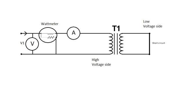
Fig.1Opencircuittestcircuit
tofig.1,definingtheequations.
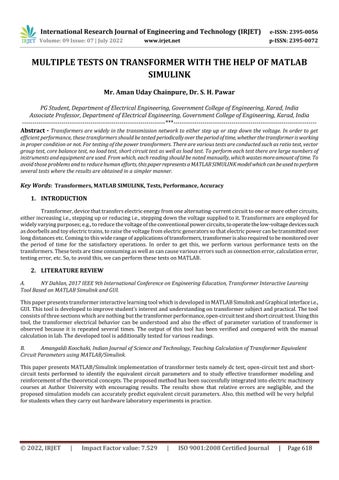
2. Shortcircuittest
Fig.2Shortcircuittestcircuit
RelatingtoFig.2,
Volume: 09 Issue: 07 | July 2022 www.irjet.net p ISSN: 2395 0072 © 2022, IRJET | Impact Factor value: 7.529 | ISO 9001:2008 Certified Journal
International Research Journal of Engineering and Technology (IRJET) e ISSN: 2395 0056
Volume: 09 Issue: 07 | July 2022 www.irjet.net p ISSN: 2395 0072
Zsc=Vsc/Isc Xsc=((Zsc)2 (Xsc)2)1/2
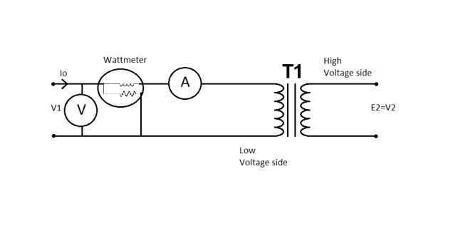
3. Loadtest
Relatingtofig.3,
%η=(W2/W1)×100
%R=(VNL VFL/VFL)×100
Measuringcurrenttransformerhasageneralpurposeaswellasaspecificpurpose.Itshouldbeaccordingtothepowersystem measurementinengineeringapplicationaswellasinthemeasurementsystemofthepracticalneedofthetypeofcurrent transformer. In practice this could be applied on higher rating of the transformer. We performed the tests based on the researchpaperdataaswellasthedatathatobtainedinourlaboratorycalculations,inthisresearchpapermeasurementsare carriedouton230V/115V,1KVA,50Hzcurrenttransformerwiththehelpofmanualtest.
Readingsobtainedareasfollows:WithRload(RheostatofthevalueR=2700hmandI=1.2A)
V1 =215V V2 =110.6V
I1 =0.218A I2 =0.016A
R1=2Ohm R2=1.1Ohm
L1=1.325Hfor100Hz,SER
L2=490mHfor100Hz,SER
O.C.Testinlab:
Poc=40W Voc=115V
Ioc=0.4A CosΦoc=0.869.
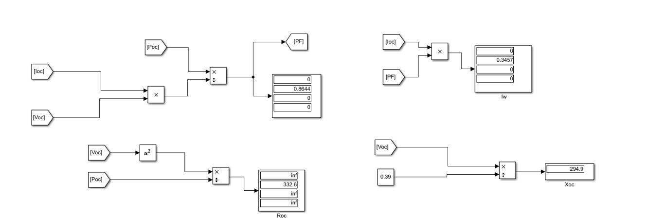
Roc=330.635 Xoc=581.10
Iµ=0.1979A Iω=0.3476A
S.C.TestinLab:
Psc=95W Vsc=27V
Isc=4.30A CosΦsc=0.85
Rsc=15.13Ohm
© 2022, IRJET | Impact Factor value: 7.529 | ISO 9001:2008 Certified Journal |
International Research Journal of Engineering and Technology (IRJET) e ISSN: 2395 0056
Zsc=6.04Ohm
Xsc=3.26Ohm
Loadtest: Efficiency=94% Regulation=1.86%
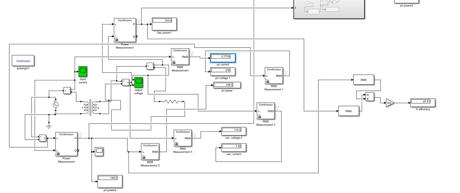
MATLABcircuitisdesignedwiththehelpSimulinkandSimscapelibraries.AnACVoltagesourceofvalue230Visconnectedon primarysideandthenonsecondaryseriesresistiveloadisconnected.Forvoltage,currentandpowermeasurements,scopes areused.Followingfigure2showstheMATLABcircuitdesign.
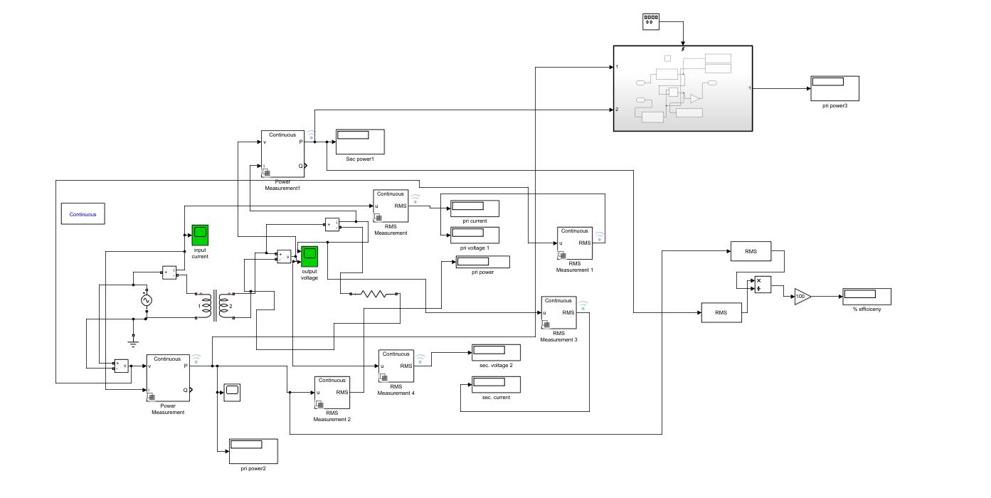
WiththehelpofapplicationofparameterestimationinMATLABSimulink,Circuitistunedforthecalculatedvaluesofvoltage andcurrent.Inparameterestimation,calculatedvaluesofinputandoutputvoltagesandcurrentareprovided.Here,calculated thevaluesofinternalresistanceandinductanceoftheprimaryandsecondarywinding.Also,sensitivityanalysisisperformed thathelpsinthathelpsinaccuracyoftheresults.Withthehelpofmultiplevalues,percentageefficiencyandpercentagevoltage regulationarecalculated.
Fig.5LoadtestMATLABSimulationresults.
Volume: 09 Issue: 07 | July 2022 www.irjet.net p ISSN: 2395 0072 © 2022, IRJET | Impact Factor value: 7.529 | ISO 9001:2008 Certified Journal
International Research Journal of Engineering and Technology (IRJET) e ISSN: 2395 0056
Theopen circuittest,orno loadtest,isoneofthemethodsusedinelectricalengineeringtodeterminethenoloadimpedance intheexcitationbranchofatransformer.Thenoloadisrepresentedbytheopencircuit,whichisrepresentedontherightside ofthefigureastheincomplete partofthecircuit. Thesecondaryofthetransformer isleftopen circuited.Awattmeteris connectedtotheprimary.Anammeterisconnectedinserieswiththeprimarywinding.Avoltmeterisoptional sincethe appliedvoltageisthesameasthevoltmeterreading.Ratedvoltageisappliedatprimary
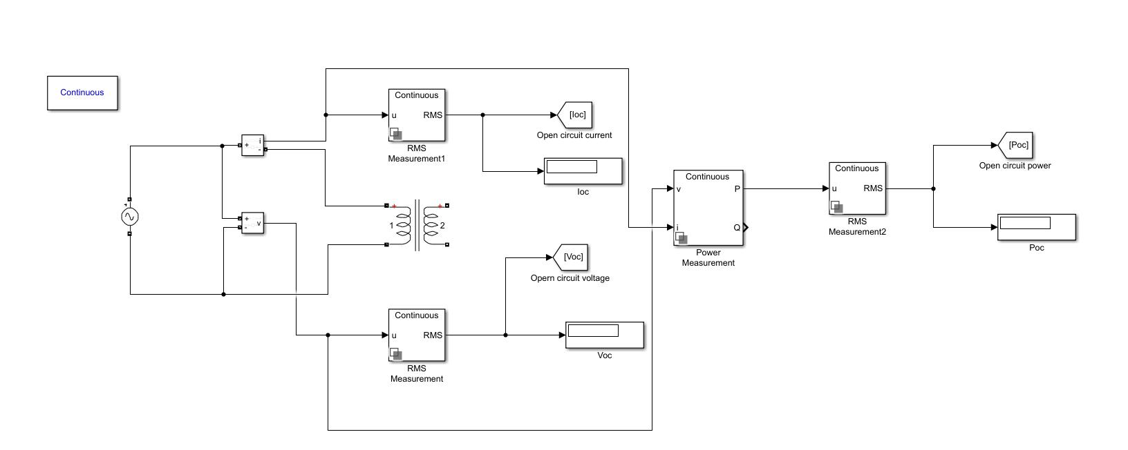
A power measurement scope is connected to the primary. A current measurement scope is connected in series with the primarywinding.Ratedvoltageisappliedatprimary.
Fig.7OCtestparameterresults
Volume: 09 Issue: 07 | July 2022 www.irjet.net p ISSN: 2395 0072 © 2022, IRJET | Impact Factor value: 7.529 | ISO 9001:2008 Certified Journal
International Research Journal of Engineering and Technology (IRJET) e ISSN: 2395 0056
Volume: 09 Issue: 07 | July 2022 www.irjet.net p ISSN: 2395 0072
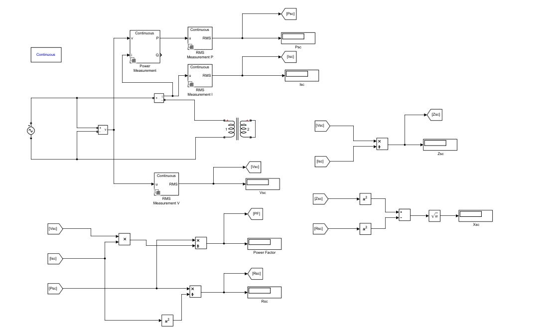
Thepurposeofashort circuittestistodeterminetheseriesbranchparametersoftheequivalentcircuitofatransformer.
Thistestisconductedonthehigh voltage(HV)sideofthetransformerwhenthelow voltage(LV)side(orthesecondary)is short circuited.Awattmeterisconnectedtotheprimaryside,anammeterisconnectedinserieswiththeprimarywinding. Withthehelpofavariac,theappliedvoltageisslowlyincreaseduntiltheammetergivesareadingequaltotheratedcurrentof theHVside.AfterreachingtheratedcurrentoftheHVside,allthreeinstrumentsreading(Voltmeter,Ammeter,andwattmeter readings)arerecorded.TheammetersreadinggivestheprimaryequivalentoffullloadcurrentIL.Asthevoltageappliedfor fullloadcurrentinshortcircuittestontransformerisquitesmallcomparedtotheratedprimaryvoltageofthetransformer, theironlossesinthetransformercanbetakenasnegligiblehere.
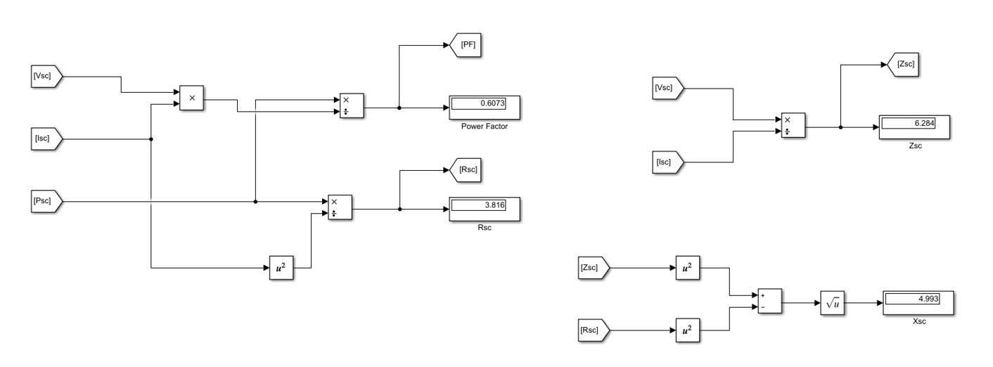
Fig.9SCtestparameterresults
2022, IRJET | Impact Factor value: 7.529 | ISO 9001:2008 Certified
International Research Journal of Engineering and Technology (IRJET) e ISSN: 2395 0056
Thispaperpresentsauser friendlyandeducation orientedtransformerlearningtoolandissuccessfullydevelopedusing MATLABSimulink.Thistoolisintendedtomaketransformertestingteachinginmoreeffectiveandeasyway.Theinterfaceof MATLABisabutton drivenprogramprovideswhichisaconvenienttoolsothatusercanrunthistoolrepeatedlytoobserve thetransformerbehaviorwithparametervariation.Byusingthistool,usercanalsoreducemanualcalculationtime.
Futureworkwillbefocusedondevelopingamorecompletelearningtoolthatconsistofalltransformerteststogether.Also,the MATLABcircuittestsdesignforotherelectricalmachinedevicessuchasinductionmachine,synchronousmachineandDC machine.
1. NYDahlan,2017IEEE9thInternationalConferenceonEngineeringEducation,TransformerInteractiveLearningTool BasedonMATLABSimulinkandGUI.
2. Amangaldi Koochaki, Indian Journal of Science and Technology, Teaching Calculation of Transformer Equivalent CircuitParametersusingMATLAB/Simulink.
3. Prof.J.H.Patil,IJIRST InternationalJournalforInnovativeResearchinScience&TechnologyTransformerTesting andAnalysisusingMATLAB/Simuink.
4. Mr. M. Subramani, International Journal of Advanced Science and Engineering Research, Investigations of Power TransformerParametersUsingCoreBalanceandVectorGroupTest
Volume: 09 Issue: 07 | July 2022 www.irjet.net p ISSN: 2395 0072 © 2022, IRJET | Impact Factor value: 7.529 | ISO 9001:2008 Certified Journal