International Research Journal of Engineering and Technology (IRJET) e ISSN: 2395 0056

Volume: 09 Issue: 07 | July 2022 www.irjet.net p ISSN: 2395 0072
International Research Journal of Engineering and Technology (IRJET) e ISSN: 2395 0056
Volume: 09 Issue: 07 | July 2022 www.irjet.net p ISSN: 2395 0072
1CSIRO Energy, Kensington, WA 6151, Australia
2CSIRO Energy, Clayton, VIC 3168, Australia
3Currently at Action Drill & Blast, Belmont, WA 6104, Australia ***
Abstract Conventional radial strain measurements in triaxialtestingare done using asmallnumberofstraingauges or cantilever radial devices. The usual restricted number of these gauges and their location does not favour capturing a full picture of material heterogeneities. Fibre Bragg Grating (FBG) sensing technology could revolutionize conventional strainmeasurement. Itoffershigher resolutionmeasurements andallows more measuringpoints, enabling 3Dshapesensing to capture localized rock mechanical changes and heterogeneities.
To integrate FBG sensing to triaxial vessels, a new end platen was designed and engineered out of carbon fibre material reinforced with epoxy resin. The platen configuration allows using conventional strain measurement devices simultaneously with FBG sensors when required. There is a high correlation, or the assumption of radially symmetric deformation regardless of the orthogonal cantilever type gauges measuring radial strain, whereas the FBG sensors measure circumferential strain.
Two hydrostatic tests were conducted on a standard aluminium plug of 76 mm in length and 38 mm in diameter. Six FBG sensors were attached to the surface of the sample. The aluminiumplug, FBG wire andplaten werepositionedand secured inside the pressure chamber using a Viton sleeve. Additionally, two orthogonal cantilever type gauges were placed on top of the test membrane.
The results show that FBG strain values are comparable to those obtainedfromthe cantileverdevices,whichindicatesthe functionality of the platen design and opens possibilities of obtaining high resolution 3D strain maps from rock samples, which is especially useful if there are heterogeneities or for reactive transport applications. The platen has so far been tested for FBG sensors only, but in principle, it would enable the integration of any fibre optic sensor
(usually cylindrical) under well controlled conditions in a laboratorywhilemeasuringtheresultingverticalandlateral deformation using strain gauges [1, 2], cantilever type gauges and Linear Variable Differential Transformers (LVDTs) [3], either individually or combined, and usually placed at the sample’s mid height. Although it is accepted thatrockdeformationcanbereliablymonitoredwiththese techniques,thosedevicesmayofferonlya limited viewof the deformation field depending on the level of heterogeneity of a given material. The impact of such simplificationcouldbeparticularlyimportant,forexample, for vuggy samples or if fractures or joints are present. Moreover, conventional electric gauges are susceptible to short circuit, e.g., when exposed to brine for a prolonged period, thermal degradation, and electromagnetic interference[4,5].
TheFibreBraggGrating(FBG)sensingtechnique[6]has established itself as a strong candidate for strain and temperature measurements, following successful applications in medical sciences, telecommunication, magneticfielddetectionandtheenergysector[7 10].FBGs’ realpowerliesinthesensor’shigh sensitivityretentionin adverse environments, multiplexing capabilities, and immunitytoelectromagneticinterferences,amongothers[5, 11,12].
Recently, multiplexing FBG sensor arrays were successfully implemented to measure the deformation of rocksamplessubjecttouniaxialcompressionunderambient conditions[12,13].However,usingFBGsensorstomeasure strain when lateral confining pressure is present (as in triaxial or hydrostatic tests) is technically challenging, especially due to the FBG wire’s fragility and limited minimumbendingradius[14].
Words: FBG Sensors, Rock Mechanics Testing, Hydrostatic tests
Atypicalrockmechanicstestinvolvestheapplicationof vertical load and lateral pressure onto a rock specimen
In this study, a new innovative end platen to integrate FBGsensorarraysintoatriaxialsystemwasdesignedand manufactured using carbon fibre reinforced with epoxy resin.Ahydrostatictestwasconductedtoverifytheplaten functionalityusingastandardaluminiumplugof76mmin length and 38 mm in diameter. For the test, an FBG wire containing six FBG sensors was inserted through the designedendplatentoreachtheplugradialsurface.TheFBG wire was then wrapped around the sample’s surface and
International Research Journal of Engineering and Technology (IRJET) e ISSN: 2395 0056
Volume: 09 Issue: 07 | July 2022 www.irjet.net p ISSN: 2395 0072
fixed using glue, and its free end was connected to an interrogator.The sample wasfinallyplacedinsidea Viton sleeve.Forthesakeof benchmarkingthestrainmeasured fromFBGtechnology,anadditionalstandardtechniquefor strainmeasurementwasalsoaddedtothesamplemounting: twoorthogonalcantilevergaugeswereplacedonthetopof the Viton sleeve, adjacent to FBG sensors 3, 4 & 5, 6, to measurethesample’sradialdeformation.Thetestwasdone under hydrostatic pressure up to 20 MPa and in a temperature controlledenvironmentofapproximately23O C.
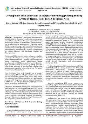
FibreBraggGrating(FBG)sensinghasgainedpopularity and received increased attention in recent years. Laying insidethecoreofanopticalfibreareFBGsensorsofdifferent wavelengthsthataresensitivetoexternaldeformationand temperature. This possibility solidifies FBGs’ multiplexing capabilities. In principle, FBG sensors work by partial reflection of broadband light that is transmitted into the systembyequipmentknownasaninterrogator(Fig 1).The reflected segment of light is of great importance and is definedbyitswavelength,knownastheBraggwavelength, λB, whichcanbecalculatedusingtheequation:
λB=2nΛ
wherenistheeffectiverefractiveindexoftheFBGandΛis the geometrical grating interval equal to the distance betweentwosuccessivealterationsoftherefractiveindex.
where represents the strain on the FBG, T is the temperaturevariation, p isthestrainoptictensorrelatedto the properties of the fibre, is the thermal expansion coefficientofthefibre,andζisthethermo opticcoefficient.
A major challenge integrating FBG sensors into a triaxial systemistoaccesstheradialsurfaceofthesamplewithout compromisingtheconfiningandporefluid(s)pressuresand temperature, nor damaging the very fragile optical fibre. Considering such constraints, a prototype end platen was designedandengineeredfromcarbonfibrereinforcedwith epoxyresin.Itfeatures(Fig 2):(i)aflatsurfaceonthetop sidetoallowstandardcoreplugstositflushduringtesting; (ii) a stainless steel ring that prevents the fasteners from damagingtheplaten;(iii)onefeedthroughnetworkatthetop centre of the platen and inclined at a 10° angle as it progressesouttotheoppositeendintheverticalorientation, toallowforthickwallcylinder(TWC)testingwithintegrated FBG;and(iv)anotherfeedthroughnetworkspirallingaround the platen from the central position, next to the internal feedthroughatthebottomendoftheplatenandexitingout onthetopsideoftheplatentofacilitateFBGintegrationinto theoutercircumferenceofstandardtestingplugs.
Fig 1:FBGsensorandthecorrespondingspectra[13]
AllvariationsinphysicalcharacteristicswithintheBragg grating zone are linked to alterations of either the geometricalgratinginterval(Λ),thecorerefractiveindex(n), or a combination of both. The relationship of the relative Braggwavelengthshift(λB)correspondingtothechangesin the mechanical strain () and the variation in the temperature (T) is expressed as a first order differential equation[6]:
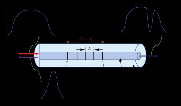
Fig 2:CSIRO’sendplatenusedtointegratetheFBG sensingtechniqueintoatriaxialrig.(a)3DCADoftheend platen,(b)end productofthemoldedplatenwithFBG wireoutofthespiralchannel,and(c)theplateninstalled insidethepressurechamberpreparingforamocktest
International Research Journal of Engineering and Technology (IRJET) e ISSN: 2395 0056
Volume: 09 Issue: 07 | July 2022 www.irjet.net p ISSN: 2395 0072
The2mmfeedthroughnetworkdesigndoublesaspore fluidlinesforflowprotocols.Theouterfeedthrough(iv)was designedtoamaximumangleof80°fromthehorizontalaxis with gradual decrements of 10° as the feedthrough progressesspirallyupwardstoallowtheminimumcurvature possible.Thistransitionisimportantasitallowsforsmooth entry of the FBG wire and prevents reflective losses while lighttravelsthroughtheFBGwire.
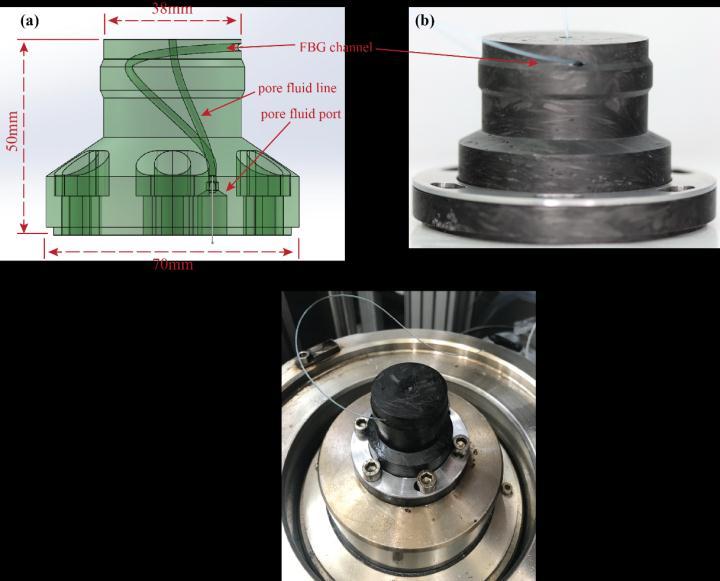
To ensure the end platen design does not impact FBG strainmeasurementunderstressconditions,ahydrostatic compression test (1 = 2 = 3 = 0) was conducted. The essence of this geomechanical test is to yield information about rock compressibility andthemagnitude ofthe pore collapsepressureifsuchfailureisachieved.Forsimplicity,a solidaluminiumplug(knownproperties)of76mminlength and38mmindiameterwaspreparedforthetest.AFiber wire with six FBG sensors model DTG LBL 1550 125, custom made by FBGS Technologies GmbH, with 125 μm claddingdiameterandOrmocercoating,wasgluedspirally alongthepluglengthusingAralditeepoxyadhesivewitha curingtimeof90seconds(Fig 3a).Theglueingwasdoneso that FBG sensors numbered 1, 3, and 5 were positioned opposedtoeachotherandatthesameheightasFBGsensors numbered 2, 4 and 6, respectively (Table 1). The range of Braggwavelengthofthesixsensorsisbetween1530to1565 nm, with a 5 nm spacing to avoid overlaps. The manufacturedwavelengthsensitivitycoefficientsassignedat ambientconditionsare0.776pm/με,8.53pm/K,and0.0023 pm/K
Aftercuring,thealuminiumplugwiththesixFBGsensors was carefully inserted into a Viton Sleeve. The assembled systemwasthenplacedinsidethetriaxialvesselontopof thenewendplatentoallowtheFBGwiretocomeoutofthe triaxialsystemandbeconnectedtoaninterrogator(Fig 3a &b).Apairofcantilever typeradials(herecalledRC 1and RC 2)wasthenplacedontopoftheVitonsleeve,asshownin Fig 3 a & b. After that, the pressure cell was closed, filled withhydraulicoil,andhydrostaticloadingcommencedat0.5 MPa/min in a temperature controlled environment set to 23°C.Twohydrostaticloading unloadingcyclesof7.5and 19.5MPa(effectiveconfiningpressure)wereconductedto ensuretherepeatabilityoftheFBGstrainmeasurements.A high accuracy, computer controlled stepper motor pump was used. A LabVIEW application recorded pressure, deformation,andtemperaturedataeverysecond.FBGpeaks datawasobtainedfromFAZTI4Femtosensesoftware(Fig 3 c), with a measuring capability of 120 dB and a 0.1 pm precision.
Toquantifythedeformationofthemembrane,whichis inevitably captured in the strain measured by the radial cantilevers placed over the sleeve, and hence allowing a morerealisticcomparisonoftheFBGstrainmeasurements withthosefromthecantilevers,anadditionaltestwasrunin
a different triaxial rig under similar temperature and pressureconditions,usinganidenticalaluminiumplugwith onecantileverattacheddirectlytotheplug’ssurface.
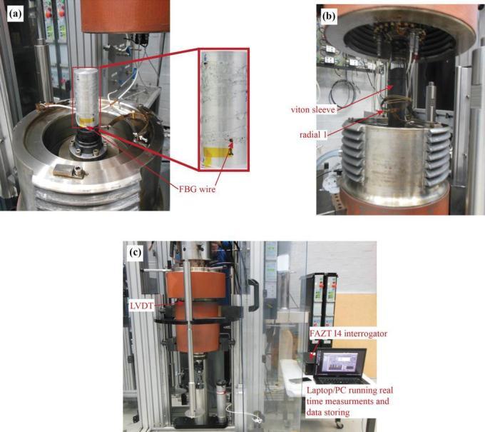
Fig 3: Sample set up in triaxial stress test vessel: (a) aluminiumplugwithFBGwiregluedtoitssurface,sittingon thenewlydesignedendplaten;(b)thesamealuminiumplug insertedintotheVitonsleeve,andradialcantileversattached to the sleeve; (c) the triaxial cell closed and interrogator communication on a PC laptopTable -1: FBG sensor locationsonthealuminiumplug
Sensor#
Distancefromthebottomendof thesample(mm)
1and2 10.0 3and4 40.3 5and6 66.3
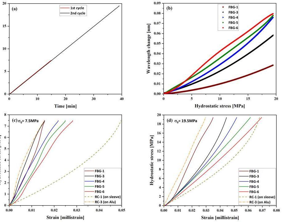
Fig 4ashowshydrostaticstressofbothcyclesvstimefor thesameloading rate.Anexampleofwavelengthshiftsof FBGs during hydrostatic loading is in Fig 4 b. The results showthatthewavelengthshiftincreaseslinearlywiththe appliedstress,consistentwiththefindingsofZhaoetal.and Leietal.[15,16].
Stress straincurvesareshowninFig 4c&Fig 4d.Data recorded by FBG sensor #2 and radial cantilever #2 were disregardedduetolowquality,hencearenotshowninthe figure.ThevariationinthereadingsfromthefivevalidFBG sensors could be attributed to: (i) nonuniformities in the glueingprocess,whichwasdonemanuallyandwhoseeffect is yet to be investigated; and (ii) the inability to manually
International Research Journal of Engineering and Technology (IRJET) e ISSN: 2395 0056
Volume: 09 Issue: 07 | July 2022 www.irjet.net p ISSN: 2395 0072
reducethereflectedopticalpower.Thelattercanbesolved byaddinganattenuatorintheFBGsystemtodealwithany round tripinsertionlosses,althoughthefluctuationsinthe strainmeasurementsarequitesmall intheorderof0.05 and 0.07 millistrain for the 7.5 MPa and 19.5 MPa, respectively. Nevertheless, it can be observed that strain dataderivedfromtheFBGsensorsshowasimilartrendto theonesderivedfromthereadingsoftheradialcantilever #3 (RC 3) (measured straight on the plug’s surface), and theyarealsoofthesameorderofmagnitude.
of the rock samples to measure 3D strain variation orthogonallyalongtheradialdirectionofsamples.
The results encouraged the design of another FBG end platen,whichiscurrentlybeingengineeredusing3Dprinted titaniumtechnology(insteadofcarbonfiberreinforcedwith epoxy resin). The material choice aims at exploring the abilityofFBGsensorstofunctionatelevatedtemperatures, allowing the performance of geomechanical tests at high temperatures(above100°C).
TheauthorswouldliketothankBruceManeyandYevhen KovalyshenofCSIROEnergyfortheirassistanceindesigning the platen. Also, many thanks to Andrey Prusenko for finalizing the design, selecting the material, and manufacturing the FBG platen. This work could not be possiblewithoutthefinancialsupportfromCSIROEnergy.
[1] Clayton C. R. I. and Khatrush S. A. A New device for measuring local axial strains on triaxial specimens. Geotechnique.1986;36:593 7.
[2] ISRM.Suggestedmethodsfordeterminingtheuniaxial compressivestrengthofrockmaterials.1972.
[3] Ibraim E. and Di Benedetto H. New local system of measurementofaxialstrainsfortriaxialapparatususing LVDT.GeotechTestJ.2005;28:436 44.
Fig 4:Summarizedgraphicalrepresentationofresults obtainedfromthisprotocol:(a)stressvstimecurvesfor bothloadingcycles,i.e.7.5MPaand19.5MPa;(b)FBG sensorswavelengthchangewiththeincreasein hydrostaticstressforthe19.5MPaloadingcycle;(c)and (d)stress straincurvesfortheloadingcycles7.5MPaand 19.5MPa,respectively,asmeasuredbyFBGsensors,RC 1 (readingontopoftheVitonSleeve)andRC 3(readingon Aluminiumsurface)
Inthiswork,weinvestigatedthepossibilityofintegrating Fibre Bragg Grating (FBG) multiplex sensors into an axisymmetrictriaxialstressvesselusingthenewlydesigned end platen. Cyclic hydrostatic stress was applied on an aluminium plug prepared with 6 FBG sensors. Simultaneously,radialcantilevergaugeswerealsousedto monitor the radial deformation of the tested plug. Results showthatFBGstrainvalues were comparabletotheones fromtheradialstraincantilevers,whichindicatesthatthe implementedFBGsensingprotocolusingthenewlydesigned platenachieveditspurposeandcanbeusedinfuturetriaxial testing campaigns. Moreover, it opens possibilities of distributingmoreFBGsensorsthroughoutthecircumference
[4] Uchida S, Levenberg E, Klar A. On specimen strain measurement with fiber optic distributed sensing. Measurement.2015;60:104 13.
[5] KovalyshenY.,S.Banks,GiwelliA.Measurementofrock strainusingFiberBraggGratingsensors.Inproceedings of: The 52nd US Rock Mechanics/Geomechanics Symposium,Seattle,Washington,USA;17 20June2018.
[6] Othonos A and Kalli K. Fiber Bragg Gratings: Fundamentalsandapplicationsintelecommunications andsensing1999.
[7] Yi XH, Chen XY, Fan HC, Shi F, Cheng XM, Qian JW. Separation method of bending and torsion in shape sensingbasedonFBGsensorsarray.OptExpress.2020; 28:9367 83.
[8] Roriz P, Silva S, Frazao O, Novais S. Optical fiber temperaturesensorsandtheirbiomedicalapplications. Sensors Basel.2020;20.
[9] SchukarV,KöppeE,HofmannD,WestphalA,SahreM, GongX,BartholmaiM,BeckU.Magneticfielddetection with an advanced FBG based sensor device. In
2022, IRJET | Impact Factor value: 7.529 | ISO 9001:2008 Certified Journal |
International Research Journal of Engineering and Technology (IRJET) e ISSN: 2395 0056
Volume: 09 Issue: 07 | July 2022 www.irjet.net p ISSN: 2395 0072
proceedings of: 30th Eurosensors Conference, Berlin, Germany;2016.
[10] Marques RD, Prado AR, Antunes PFD, Andre PSD, Ribeiro MRN, Frizera Neto A, Pontes MJ. Corrosion resistantFBG basedquasi distributedsensorforcrude oil tank dynamic temperature profile monitoring. Sensors Basel.2015;15:30693 703.
[11] da Silva FalcãoB,EstebanL,GiwelliA, Kovalyshen Y , Banks S, Al Yaseri AZ , Keshavarz A, Iglauer S. Monitoring fluid migration using in situ nuclear magnetic resonance core flooding system integrated with fiber optic sensors: A proof of concept. In proceedings of: The 35th International Symposium of theSocietyofCoreAnalysts(SCAAnnualSymposium), OnlineEvent;13 16September2021.
[12] SunYK,LiQ,YangDX,FanCK,SunA.Investigationofthe dynamic strain responses of sandstone using multichannel fiber optic sensor arrays. Engineering Geology.2016;213:1 10.
[13] daSilvaFalcãoB,GiwelliA,NogueiraKiewietM,BanksS, Yabesh G, Esteban L, Kiewiet L, Kovalyshen Y, MonmussonL,Al YaseriA,KeshavarzA,IglauerSStrain responsesofoutcroplimestonerockusingmultiplexed FBG sensor arrays: An experimental investigation Manuscriptsubmitted2021
[14] Yabesh G, Giwelli A, Nogueira Kiewiet M, Kiewiet L, EstebanL,daSilvaFalcãoB,BanksS,Al YaseriA.Can FBG sensors measure rock deformation under hydrostatic pressure? In proceedings of: ARMA/DGS/SEG International Geomechanics Symposium,Dhahran,SaudiArabia;2021.
[15] Zhao WS, Zhong K, Chen WZ. A Fiber Bragg Grating boreholedeformationsensorforstressmeasurementin coalminerock.Sensors Basel.2020;20
[16] LeiWL,ChaiJ,ZhangDD,OuyangYB,MaZ,DuWG,Liu YL. Experimental study on overburden deformation evolution under mining effect based on Fiber Bragg Gratingsensingtechnology.JSensors.2020;2020
© 2022, IRJET | Impact Factor value: 7.529 | ISO 9001:2008 Certified Journal