International Research Journal of Engineering and Technology (IRJET)
e-ISSN: 2395-0056
Volume: 09 Issue: 07 | July 2022
p-ISSN: 2395-0072
www.irjet.net
COMPUTATIONAL FLUID DYNAMIC ANALYSIS OF A PULSE JET ENGINE Harikant Chouriya 1, Chandrakant Mengoliya 2, Purushottam Sahu3 1Research
Scholar, BM College of Technology, Indore RGPV, Bhopal BM College of Technology, Indore RGPV, Bhopal 3 Purushottam Sahu Professor, Dept. of Mechanical Engineering, BM College of Technology, Indore RGPV, Bhopal ---------------------------------------------------------------------***--------------------------------------------------------------------be directed in the same direction, maximizing thrust. This Abstract - The quality of combustion in the combustion 2
U-shape has the obvious advantage of increasing thrust, but it also has several disadvantages. The largest advantage is that they have nearly twice the cross-sectional area of a traditional straight pulsejet. This combined with the fact that drag increases as the square of velocity, results in a significant drag penalty at higher forward flight speeds. Nonetheless, this U-shaped design is still popular among hobbyists who tinker with electronics pulse jet.
chamber has a significant impact on the thrust force generated by the pulsejet engine, which is dependent on the number of fuel inlets. This study employs the CFD technique to investigate the pulsejet engine, specifically the thrust generated by the eddy dissipation combustion model and the finite rate chemistry combustion model. The comparative study is based on the generation of enthalpy, pressure, and thrust force. The CAD model of the pulse jet engine is created with Creo design software, and the CFD analysis is performed with ANSYS CFX software. The static enthalpy, pressure, and thrust force of three different pulse jet designs are calculated using both eddy dissipation and finite rate chemistry combustion models.
1.2 Jet Theory and Design For nearly a century, the pulsejet's operation has been fairly well understood. Because the jet has few moving parts, its acoustic properties are almost completely described throughout the jet. Over the last decade, NC State has conducted extensive computational and experimental research, and this paper builds on that work. Any pulsejet's main design consists of three main sections, as shown in Figure 1.4. On each cycle, the inlet is a round tube that serves as the primary method of introducing fresh air into the system. It has the smallest crosssectional area because it is the shortest section of the pulsejet.
Key Words: Pulsejet, Fuel Inlet, Combustion, CFD, Thrust 1. INTRODUCTION A pulsejet engine is a jet engine that uses the heat of a fire. The pulsejet engine can be built statically with a few missing components. Pulsejet engines are lightweight jet engines with a negative congestion rate, which results in some low pressure. Another noteworthy line of research for pulsejet engines is the pulse engine, which involves repeated engine shutters and can provide high pressure and efficiency. One of the most basic forms of propulsion known to man is the pulsejet. They are well-known for having few to no moving parts, scalability, low cost, ease of use, and extremely high noise levels.
2. Objectives The goal of this research is to use CFD to investigate pulsejet engines by increasing the number of fuel inlet nozzles and diffuser angle. The specifics are as follows: 1> CAD design of a pulsejet engine using Creo 2.0 software 2> CFD analysis with ANSYS CFX software based on the base design 3> For base design, determining thrust generated, pressure plot, and velocity plot 4> Computer-aided design (CAD) modelling of new designs with multiple fuel inlets 5> CFD analysis with ANSYS CFX software on a new design with multiple fuel inlets
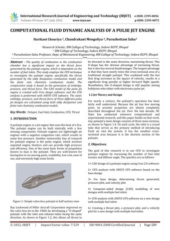
Figure 1: Simple valve less pulsejet in half section view Ray Lockwood of Hiller Aircraft Corporation improved on the valve less jet in the 1960s by developing a "U-shaped" pulsejet with the inlet and exhaust tubes facing the same direction. As shown in Figure 1.2, this allows all thrust to
© 2022, IRJET
|
Impact Factor value: 7.529
6> Creating a thrust plot, a pressure plot, and a velocity plot for a new design with multiple fuel inlets.
|
ISO 9001:2008 Certified Journal
|
Page 589