International Research Journal of Engineering and Technology (IRJET) e ISSN: 2395 0056

Volume: 09 Issue: 07 | July 2022 www.irjet.net p ISSN: 2395 0072
International Research Journal of Engineering and Technology (IRJET) e ISSN: 2395 0056
Volume: 09 Issue: 07 | July 2022 www.irjet.net p ISSN: 2395 0072
1Research Scholar, BM College of Technology, Indore RGPV, Bhopal
2Purushottam Sahu Professor, Dept. of Mechanical Engineering, BM College of Technology, Indore RGPV, Bhopal 3 Chandrakant Mengoliya BM College of Technology, Indore RGPV, Bhopal ***
Abstract -Helical coil heat exchangers are a common piece of equipment in many industrial applications. Because of their higher heat and mass transfer coefficients, narrow residence time distributions, and compact structure, helical coils are widely used as heat exchangers and reactors. The current work employs CFD analysis of heat transfer in a tube in tube helical coil heat exchanger to investigate the effect of outer and inner tube flow rates on heat transfer coefficients. The fluid used in the CFD simulation is Al2O3/water (1 percent volume fraction). The analysis is carried out for various fluid inlet velocities, namely 0.01m/s, 0.02m/s, 0.03m/s, 0.04m/s, and 0.05m/s. Comparison of parameters such as temperature plot, pressure drop and heat transfer coefficient, Nusselt number
Key Words: Heat Transfer, Pressure Drop, Reynolds Number, Nusselt number, CFD Model
Heat exchanger thermal efficiency is adequate for the commercial operation of industrial machinery. Several active or passive strategies, such as changing the fluid passage,addingspincreators,andmixingNanofluids, are used to improve the thermal efficiency of heat exchanger pipe sideways convection heat transmission. These methods reduce plant irreversibility; improve heat transfer efficiency, volume, and fluid flow characteristics. Researchers from all over the world have been studying the thermal efficiency generation of convective heat transmission in tubes using various types of addition as a liquid way transformer. The majority of the addition geometry, normal velocity gradients, and works as a mixing inducer, disorder swirl generator, and abode time accompaniment.
The scale of heat exchangers cannot become compact if the fluids complex has low thermal conduction and efficiency is too low due to low thermal conduction of fluids. Heat transmission improvement in the heat exchanger is possible with the development of the fluid's heat assets. It is a straightforward method of increasing heatpotentialbysuspendingsmall,fineparticlesinfluids. Forexample,differenttypesofpowders,metal,non metal, and polymeric particles, can be used to frame slurries in
liquids. Heat capacity is greater in complete suspended fluidsthaninsimplefluids.
The main enterprise in the application of Nano phase elements to adjust the thermal exchange execution of normal solutions is Nano fluid readiness. The term "Nano fluid" refers to more than just a solid mixture of fluids. Some unusual prerequisites are required, such as an interruption, constant interruption, strong interruption, small particle collection, and no liquid concoction shift. In general, the following are effective suspension planning techniques:
1. Changing the estimated pH of the suspension; 2. Using both activators and dispersants for surfaces; and 3. Allowingtheuseofacceleratedvibration.
The CAD model of helix geometry is built in Creo modelling software using dimensions from the literature [50]. 'The cylindrical part of the insert has a diameter of 19mm,andthehelicalinsertsweptaroundithasaheight of4mmandawidthof1mm.Theinsertisapproximately 350 mm long and has a rotation ratio of 1.92. It has a 25 mm inlet downwash and ends 50 mm before the outlet'[50]. The CAD model is encased in a cylindrical enclosurethatconformstothedimensionsspecifiedinthe literature[50].
A heat exchanger's performance will be improved by the introduction of nanofluids since they offer a faster rate of heattransferthanbasefluids.
In order to improve the heat transmission capabilities of helical insert tubing, the impact of nanofluids must be studied.
Previous studies focused on improving heat transmission using twisted tapes by employing nanofluids and tabulators. To improve heat transfer enhancement, some studies have used parametric optimization of twisted
International Research Journal of Engineering and Technology (IRJET) e ISSN: 2395 0056
Volume: 09 Issue: 07 | July 2022 www.irjet.net p ISSN: 2395 0072
tapes.Inordertoimproveheattransmissionanddecrease friction coefficient, this study investigated the usage of Al2O3/waterandCuO/waternanofluids.
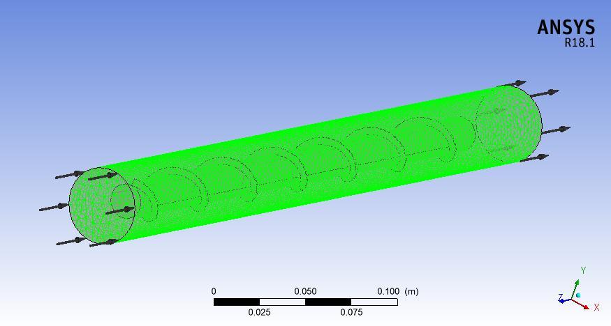
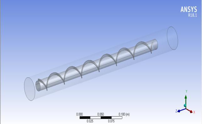
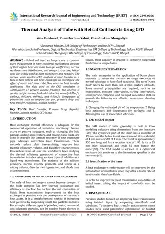
Figure4.1:IntroducedCADmodelofthehelixinANSYS designmodeler
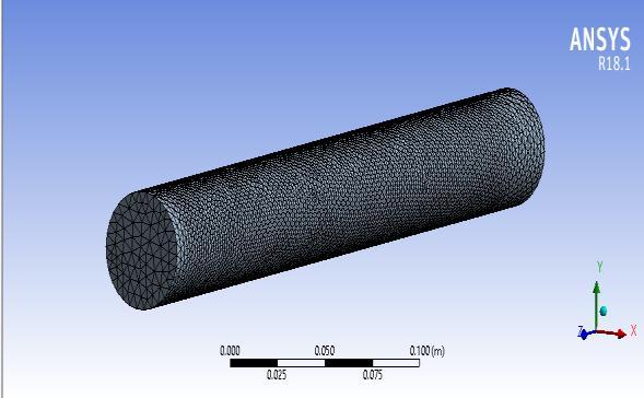
Using tetrahedral elements, the CAD model meshes. The size of significance is set at fine and inflation is set at neutral.
Figure4.3:Fluiddomain WATERASFLUIDCUO(2%VOLUMEFRACTION)
CuO/water(2percentvolumefraction)isusedasthe fluid in the third CFD simulation. Different fluid inlet velocities, including0.01m/s,0.02m/s,0.03m/s,0.04m/s,and0.05 m/s,areusedintheanalysis.
Figure4.2:ImportedCADmodelofahelixinANSYSdesign modeler
The number of generated nodes is 66669 and 334874 is the number of generated elements. The transition ratio is setto0.77andthegrowthrateissetto1.2.
The loads and boundary condition involves domain definition, turbulence definition, and material definition. Fluid form and reference pressure set to 1atm are the specifieddomain.RNGk epsilonwastheturbulencemodel andthermalenergywastheenergymodel.
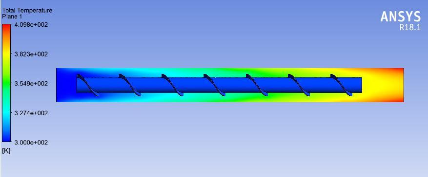
Figure5.7:temperatureplotofCuO/waterasfluid(u=.01)
CuO/water(2percentvolumefraction)isusedasthefluid, andthetemperaturemapisobtainedforhelicalscrewtape insert in a pipe. The contour map shows how the temperaturerisesas one moves from the fluid inlet to the fluidoutputwall.Theheavybluetint,whichgetslighteras yougetclosertothe exit,indicatesa temperatureof 300K at the fluid input. The contour plot displays the temperatureshiftfrom300Kto354Kinthemiddleregion, which is indicated by green, and 409K towards the exit, which is indicated by red on the edge and yellow in the centre.
International Research Journal of Engineering and Technology (IRJET) e ISSN: 2395 0056
Volume: 09 Issue: 07 | July 2022 www.irjet.net p ISSN: 2395 0072
which is indicated by green, and 409K towards the exit, which is indicated by red on the edge and yellow in the centre.
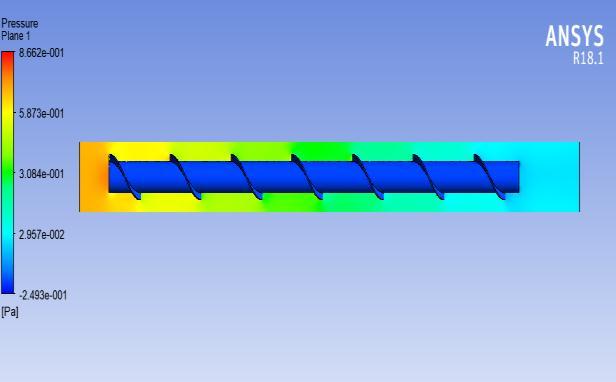
In figure 5.8 above, the pressure plot obtained for CuO/water (2 percent volume fraction) as fluid is Illustrated. As Illustrated by the orange and dark red colors, the plot indicates higher inlet pressure. The pressure near the helical screw tape is high in the magnitude of .86Pa which reduces as the fluid passes through the coil and move towards the exit. The pressure atexitis.24Pa (negative)asshownbythedark bluecolor region.
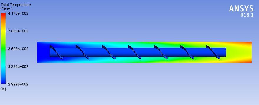
Figure5.10:TemperatureplotofAl2O3/waterasfluid (u=.01)
Al2O3/water (1 percent volume fraction) is used as the fluid, and the temperature map is obtained for the helical screwtapeinsertinthepipe.Thecontourplotshowshow the temperature rises as you move from the fluid inlet to thefluidoutletwall.Theheavybluetint,whichgetslighter as you get closer to the exit, indicates a temperature of 300K at the fluid input. The contour plot shows a temperaturedifferencefrom300Kto358Kinthemiddle, which is shown bythecolour green, to 417 K towardsthe exit,whichisshownbythecolourredontheedgeandthe colouryellowinthemiddle.
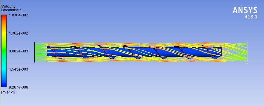
In figure 5.9 upper, the velocity streamline obtained for CuO/water as fluid is Illustrated. The plot indicates a .009m/s fluid inlet velocity at the domain inlet that changes as the fluid passes through the helix region. The streamlined flow of fluid changes to turbulent flow and remains turbulent till the fluid reaches the exit of the domain. The fluid velocity at the helix zone is .018m/s asillustratedin red colored lines while fluid velocity at the outletisthesameasthatoftheinlet.
CuO/water(2percentvolumefraction)isusedasthefluid, andthetemperaturemapisobtainedforhelicalscrewtape insert in a pipe. The contour map shows how the temperaturerisesas one moves from the fluid inlet to the fluidoutputwall.Theheavybluetint,whichgetslighteras yougetclosertothe exit,indicatesa temperatureof 300K at the fluid input. The contour plot displays the temperatureshiftfrom300Kto354Kinthemiddleregion,
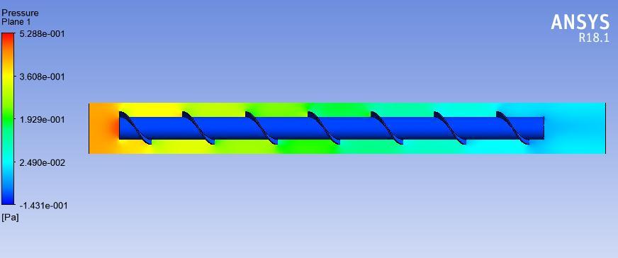
Figure5.11:PressureplotofAl2O3/waterasfluid(u=.01)
The pressure plot for the fluid Al2O3/water (1% volume fraction)isshowninFigure5.11top.Orangeanddarkred colors used in the plot demonstrate higher inlet pressure. As the fluid moves throughthe coil and toward the outlet, thepressureatthehelicalscrewtape,whichishighbythe order of.52Pa, decreases? The dark blue hue zone on the graphindicatesthatthepressureatexitis.24Pa(negative).
International Research Journal of Engineering and Technology (IRJET) e ISSN: 2395 0056
Volume: 09 Issue: 07 | July 2022 www.irjet.net p ISSN: 2395 0072
6. A 34.04 percent heat transmission related to water was observed when Al2O3/water nanofluids were used at a fluidvelocityof.05m/s.
7. The FF dropped as the RN increased for all fluids, includingwater,Al2O3/water,andCuO/water.
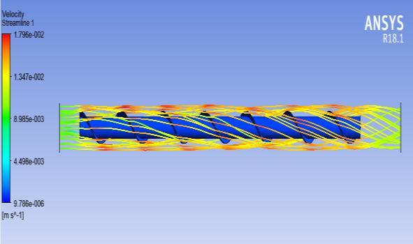
Figure5.12:StreamlineplotofAl2O3/waterasfluid (u=.01)
The upper figure 5.12 shows the velocity streamlines obtained for the fluid Al2O3/water.The graphshowshow the fluid's initial inlet velocity, which is 0.89 m/s at the domain inlet, changes as it passes through a helix's zone. Thefluid'sstreamlinedflowtransformsintoturbulentflow and stays turbulent all the way to the domain's exit. As shown by the red lines, the fluid velocity at the helix zone is.017m/s,whilethefluidvelocityattheoutletisequalto thatattheintake.
To investigate how nanofluids affect the spiral screw tape addition tube's heat transmission properties, a numerical simulation is run. The CFD study showed how well it worked at analysing the properties of heat transmission and fluid flow via pipes. When compared to experimental testing methods, using computer simulation software is moreaffordableandquicker.
1.TheNNrosewithanincreaseinRNforallfluidsthatcan be linked to an increase in heat transfer at higher fluid velocities. The fluid flow becomes turbulent with an advancedheattransferfrequencyathigherfluidvelocities.
2. The use of Al2O3/water nanofluids has significantly enhancedthecharacteristicsofwater'sheattransmission.
3. Using CuO/water nanofluids has resulted in decreased heattransferfeaturescomparedtowater,whichhasahigh frictionfactor.
4.Comparedtowaterwithalowerfluidvelocityof.01m/s, the use of Al2O3/water nanofluids has improved heat transmissionby43.7%.
5.TheuseofAl2O3/waternanofluidsledtoa41.5percent increase in heat when compared to water with a fluid velocityof.03m/s.
[1] L.H. Tang, M. Zeng, Q.W. Wang, Experimental and numericalinvestigationontheair sideperformanceoffin and tube heat exchangers with various fin patterns, Experimental Thermal and Fluid Science 33 (2009) 818 827.
[2] Mao Yu Wen, Ching Yen Ho, Heat transfer enhancement in a fin and tube heat exchanger with improved fin design, Applied Thermal Engineering 29 (2009)1050 1057.
[3] ParinyaPongsoi, PatcharapitPromoppatum, SantiPikulkajorn,SomchaiWongwises,Effectoffinpitches ontheair sideperformanceofL footedspiralfin and tube heat exchangers, International Journal of Heat and Mass Transfer59(2013)75 82.
[4] A. Nuntaphan, T. Kiatsiriroat, C.C. Wang, Airside performance at low Reynolds number of cross flow heat exchanger using crimped spiral fins, International Communications in Heat and Mass Transfer 32 (2005) 151 165.
[5] ParinyaPongsoi, SantiPikulkajorn, ChiChuan Wang, SomchaiWongwises, Effect of fin pitches on the air side performance of crimped spiral fin and tube heat exchangers with a multipass parallel and counter crossflowconfiguration, International Journal of Heat and MassTransfer54(2011)2234 2240.
[6] ParinyaPongsoi, SantiPikulkajorn, ChiChuan Wang, SomchaiWongwises, Effect of number of tube rows on the air side performance of crimped spiral fin and tube heat exchanger with a multi pass parallel and counter cross flow, International Journal of Heat and Mass Transfer 55 (2012)1403 1411
[7] ThirapatKuvannarat, Chi Chuan Wang, Somchai Wong wises,Effectoffinthicknessontheair sideperformanceof wavy fin and heat exchangers under dehumidifying conditions,InternationalJournalofHeatandMassTransfer 49(2006)2587 2596
[8] Chi Chuan Wang, Jane SunnLiaw, BingChwen Yang, Airside performance of herringbone wavy fin and tube heat exchanger data with larger diameter tube, InternationalJournalofHeatandMassTransfer54(2011) 1024 1029.
International Research Journal of Engineering and Technology (IRJET) e ISSN: 2395 0056 Volume: 09 Issue: 07 | July 2022 www.irjet.net p ISSN: 2395 0072
[9] Han Taw Chen, Wei Lun Hsu, Estimation of heat transfer coefficient on the fin of annular finned tube heat exchangers in natural convection for various fin spacings, InternationalJournalofHeatandMassTransfer50(2007) 1750 1761.
[10] JayaramThumbe, Samuel R, Rajath K, SaiSuparna K &RajuPoojari, March 2017 Computational analysis of double pipe counter flow heat exchanger using fins attached to the inner pipe. International Journal of EngineeringResearchesandManagementStudies[ICAMS:] 98 107