International Research Journal of Engineering and Technology (IRJET) e ISSN: 2395 0056

Volume: 09 Issue: 07 | July 2022 www.irjet.net p ISSN: 2395 0072
International Research Journal of Engineering and Technology (IRJET) e ISSN: 2395 0056
Volume: 09 Issue: 07 | July 2022 www.irjet.net p ISSN: 2395 0072
Chandan Sanjiv Verma1 , Pratyusha Gajbhiye2 , Shilpa Vinchurkar3
1 2PG Student, Department of Mechanical Engineering, G.H.R.C.E, Nagpur, Maharashtra, India 3Assistant professor, Department of Mechanical Engineering, G.H.R.C.E, Nagpur, Maharashtra, India ***
Abstract - heat is energy, so energy is one of the important issues in terms of the use of refrigerants and the protection of the global environment. This waste heat leads to global warming when the heat in the area rises, and it is not good for the ozone layer, so it affects the environmental conditions. Therefore, it is necessary to take concrete measures to save energy by using waste heat. I tried to use the waste heat from the condenser of the refrigerator. This heat can be used for many household and industrial purposes. With minimal construction, maintenance and operation costs, this system is very useful for home use. This is a valuable alternative approach to improving overall efficiency and reusing waste heat. Technically feasible and economically viable.
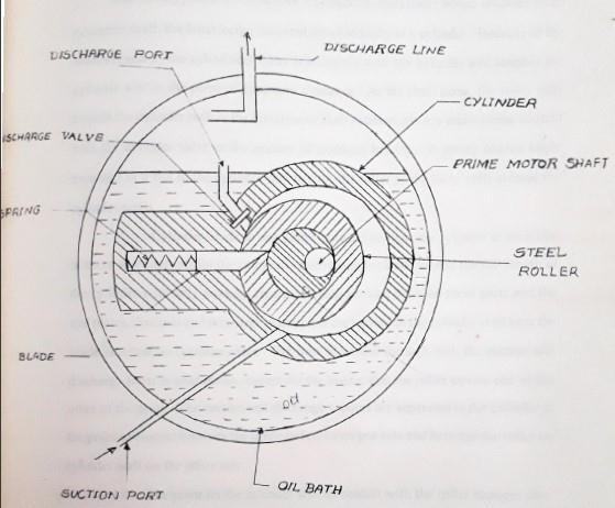
With the aim of saving energy and to reduce global warming effect, our work focuses on the valorization of the waste heat evacuated by the condenser of a refrigeration machine (air conditioner) for the desalination of sea water. In this paper, we have realized the concept of a new system that combines air conditioning and desalination. The modelling of the heat exchanges of each part of the system is realized. To improve the performance of the system, various experimental tests are represented and discussed.
Key Words: Refrigeration, desalination, condenser, global warming, etc.
The vapour compressor system employs the main components as Evaporator compressor. Expansion Device and condenser. The heat sucked by refrigetant from evaporatorandheataddedincompressorisextracted,then it can be useful for other purposes. The amount of heat is directlyproportionaltotherefrigerationcapacityofplant. So,theheatutilizationcanbeeconomicalforlargecapacity plants.
Thecondenseriskeyelementforourproject,Theaimofthe projectistodesignacondenserwhichisaheatexchanger which will cause the heat transfer from the refrigerant to water.Theheatedwateristobeusedforlowtemperature applications. The data required i.e., capacity, refrigerants etc.,Nagpurthecapacityofplantis30TR.Theheattransfer from refrigerant to water is assurned to be by natural convection The condensation of refrigerant is film condensation.Thebasicaimofdesigningtheheatexchanger is to fuel the length of coil for complete condensation of refrigerant,raisingthewatertemperatureby50C.
TheScienceofthermodynamicdealswiththequantitative transitionandrearrangementofenergyasheatinbodiesof matterHeattransferistheSciencewhichdealswiththerate of exchange of heat between hot cold bodies called the sourceandreceiver.Therearethreedistinctwaysinwhich heat may pass from a source to a receiver. Almost all engineering applications are based on this. These are Conduction.ConvectionandRadiation.
Conductionheattransferistheprocessbywhichenergy is transferofkineticenergyatamolecularlevel.Energyflow occursinthedirectionfromareasofhighertemperatureand highermolecularenergyleveltoareaoflowertemperature andlowermolecularenergylevel.
q=KA(dT/dx) Whereq=heattransferredinxdirection dT/dx=Temperaturegradientinxdirection A=Areanormaltoternperaturegradient K=Thermalconductivity. ThisequationiscalledFourierlaw.
Convection heat transfer is the transport of energy to or fromacombinedaction.conductionheattransferandfluid motion.Convectionheattransferatsolidfluidsurfacesisof most common interest, but fluid fluid interfaces are also encounteredForcedconvectionheattransferinvolvesfluids that are moved by some mechanical means. Free natural convectionheattransferreferstobuoyantconvectionwhich results from the influence of gravity upon fluids density difference induced by the heat transfer process itself Convective heat transfer coefficients are generally characterizedinthetermsof'h',whichisemployedin q=hA(Tl T2) where,q=Rateofheattransfer A=Surfacearea (T1 T2)=Temperaturedifferencebetweensurface andbulkfluid.
This equation is known as Newtonion law of cooling. The flow regions whether laminar or turbulent, have a major influence on convection heat transfer coefficients are practicallyappliedthroughcertaincorrelationsandrequire
International Research Journal of Engineering and Technology (IRJET) e ISSN: 2395 0056
Volume: 09 Issue: 07 | July 2022 www.irjet.net p ISSN: 2395 0072
knowledge of thermophysical properties of the fluid, the fluidvelocityfield,andthesurfacegeometry
Thermalradiationisaformofelectromagneticenergy.Itis travelingatthespeedoflightthroughHomogeneousmedia. It is characterized by the frequency range of the electromagneticspectrum.Thatincludesthevisibleportions and extends through the infrared. At any particular temperaturethermalradiationenergyisemittedbyabody overawidebandoffrequencies.
Arefrigerantisasubstancewhichwillabsorbtheheatfrom the source (at lower temp.) and dissipate the same to the sink(athighertemp.)eitherintheformoflatentheatorin theformofsensibleheat.
Theimportantpropertiesanidealrefrigetantshould possessare:
1) Positiveevaporatingpressure: leakage of atmospheric air into the system is preventedduetopositiveevaporatingpressure.
2) Lowercondensingpressure: lowercondensingpressurepermitstheuseoflight weightequipmentandpipingofthehigh pressure sideofthesystem.
3) Highcriticaltemperature: Thecritical temperatureof therefrigerantshould be high as compared to the condensing temperature.Duetothispowerconsumptionwillbe less.
4) Lowfreezingtemperature: Freezingtemperatureoftherefrigerantshouldbe low enough as compared to evaporating temperaturetopreventsolidificationandchoking to the pipeline andvalves.
5) Specificheatofliquidshouldbelowtoincreasethe C.O.P.
6) HighlatentHeatVaporization: To extract more amount of heat from the cooling material (cooling chamber) per unit weight of refrigerant.
7) Lowspecificvolume: Toreducethesizeofcompressor.
1) Ammonia:
It has condensing pressure (about 12bar), high evaporatingpressurehereIatentheat(1212kj/kg at 15C). Its critical temperature is 132.6C and critical pressure is 116 bar and freezing temperatureis 77.8C(low).Ithaslargelatentheat, andithasmoderateworkingpressures.
2) Carbon Dioxide(C02):
It has specific volume and therefore suitable for ships where space is a vital consideration. The criticalpointofCO2isanddryice(solidC02)boils at 78.5Catis81Catmosphericpressure.Ithaslow critical temperature (31C) which is below condenser temperature and freezing point is sufficientlylow( 110C).Itischeapnon toxic,non corrosiveandnon flammable.Thedisadvantageof COishighworkingpressure(70bar)duetowhich powerrequiredisgreaterandC.O.Pisless.
3) Air:
Airisavailablefreeofcost,itisnontoxicandnon flammable. It has low C.O.P. Dry air is used in aircraft air conditioning where low weight is more important that the efficiently.
4) Freon 11orTrichloro monofluro methaneCCI3(F): It is colorless. non corrosive, non toxic and non flammable liquid. Commercial name is F 11. At atmospheric pressure its boiling temperature is 23.8C which is relatively high. It has a freezing temperatureof 111Candacriticaltemperatureof 197.8C. Due to low operating pressures and high volumes,centrifugalcompressorsareusedwiththis refrigerant.Itisusedforairconditioningandwater chillingapplications.
5) DicholoroDifluro methane freon12(CCl2F2): Its commercial name is F 12. It is colorless, odourless and non toxic. Boiling ternperature is 29.8Catatmosphericpressure.Ithashighcritical temperature(111.5C)andlowfreezingtemperature of 157.8C. Its latent heat of vaporizations is low anddielectricstrengthishigh.Itsspecificvolumeis smallascomparedtothatofammonia.
6) Difluro monochloro methane (CHCIF2) Freon 22: Itboilsat 40Catatmosphericpressure.Itisdenser compared to ammonia and its evaporating temperatureislow.Itisusedinsmallandmedium commercialplants.
International Research Journal of Engineering and Technology (IRJET) e ISSN: 2395 0056
Volume: 09 Issue: 07 | July 2022 www.irjet.net p ISSN: 2395 0072
Therearevariousmethodsofrefrigeration:
1) Icerefrigeration
2) Evaporativerefrigeration
3) Refrigerationbyexpansionofair.
4) Refrigerationbythrottlingofgas.
5) Vapourabsorptionsystem.
6) Vapourcompressionsystem.
7) Steamjetrefrigeration.
Dryicerefrigeration.
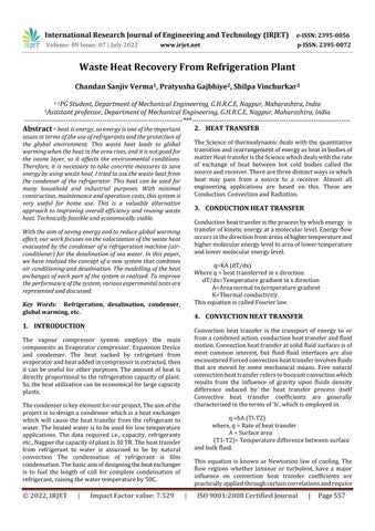
Theabsorptionrefrigerationsystemisheatoperatingunit whichusesarefrigerantthatisalternatelyabsorbedbyand liberatedfromtheabsorbent.Minimumno.ofprimaryunits essential in absorption system includes evaporator, absorber, generator, and condenser figure shows a simplifiedflowdiagramofanammoniaabsorptionsystemin which water serves as the absorbent. During the compression stroke the vapour is compressed isentropicallytopressureP2andtemperatureT2delivered out from the compressor (P2). P2 shows the vapour in superheatedstate.Thevapourat2passesandtocondenser inwhichthecoolingwaterissuppliedtoremoveheatfrom the vapour. Thus, vapour is first cooled to the saturated temperature at pressure p2 and further removal of heat, condensesittoliquidremovingitslatentheattillpt3Thus, to carry out this operation, the saturation temperature correspondingtopressureP2shouldbysufficientlyhigher than the temperature of cooling water for efficient heat transfer.
Thehigh pressureliquidisnowexpandedthroughathrottle valve,oftheliquidat3throttlestolowerpressureP1and theconditionobtainedaftertheconstantenthalpyexpansion isshown4Afterthrottling,wegetIuqidpartlyevaportedat lowertemperatureT4andlowerpressurep1,thusafterthe throttlevalvewegetwetvapouratlowtemperature.This vapour now passes through evaporator coils immersed in brine or the chamber to be refrigerated. These vaopur absorblatentheatfrombrineinfurtherevaporatingitself. The vaopur may reach condition 1 i.e., dry saturated pressureP,thuscompletesthecycleabsorber.
Thestrongammoniasolutionthusformedisthenpumped intothegenerator.Thepumpincreasesthepressureofthe solutionabout10kg/cm.Thestrongsolutionofammoniais heatedbyexternalmeans(steamorgas),andintheheating process,therefrigerantvapourisdrivenoutofsolutionand the same heat is given out to the condenser, where it is condensedtolowpressurelevelbyanexpansionvalveand thenreturnedtotheabsorber.
The high pressure liquid ammonia is passing through a throttlevalvetotheevaporatorwhereitabsorbsitslatent heat of vaporization and maintains the cold. The dry ammonia vapour is coming out of evaporator which is allowedtomixwiththeweaksolutionofammoniasprayed intheabsorber.
Thiscompletesthecycle.
Thevapourrefrigerationsystemsnowadaysoneuniversally usedforallpurposerefrigeration.Itisgenerallyusedforall industrial purposes from a small domestic unit of 0.5 ton capacitytoanairconditioningplantofcinemahallof200 toncapacity.Thevapourcompressionrefrigerationplantis showndiagrammatically.
COMPONENTS OF VAPOUR COMPRESSION SYSTEM.
Themaincomponentsofvapourcompressionsystemare: 1) Compressor. 2) Evaporator. 3) Condenser. 4) Throttlingdevice.
Thetwotypesofcompressorsaregenerallyusedin vapourcompression
1) Reciprocatingcompressor. 2) Rotarycompressor. 1) Reciprocatingcompressor:
Thereciprocatingcompressoristhemostwidely used type being employed in all field of application, it is especially adoptable for used with refrigeration requiring relatively small displacement and condensing at relatively high pressure. Among the refrigerants used extensivelywithreciprocatingcompressorareR 12,R 22,R 500,R 502andR 717Reciprocating compressorsareavailableinsizesrangingfrom 1/8 hp (approx. 90W input) in small domestic
International Research Journal of Engineering and Technology (IRJET) e ISSN: 2395 0056
Volume: 09 Issue: 07 | July 2022 www.irjet.net p ISSN: 2395 0072
unitsupto250tonsormoreinlargeindustrial installations. Reciprocating compressor may be single acting or double acting. In single acting compressors,compressionofthevapouroccurs only on one side of the piston and once during eachrevolutionofcrankshaft,whereasindouble acting compressors. Single acting compressors are usually of the enclosed type wherein the piston is driven directly by a connecting rod workingoffthecrankshaft,bothconnecting,and crankshaftbeingenclosedinacrankcase,which is pressure tight to the outside.
Rotarycompressorsincommonuseareoffourgeneral designs:
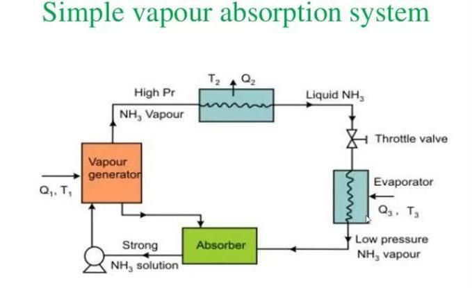
i.
Therollingpistontypeemploysacylindricalsteel roller which revolves on an eccentric shaft. the latter being mounted concentrically in a cylinder becauseoftheshafteccentric,thecylindricalroller is eccentric with the cylinder and touches the cylinderwallatthepointofminimumclearance.As theshaftturns,therollerrollsaroundthecylinder wall in the direction of shaft rotation, always maintainingcontactwiththecylindervalveinthe mannerofcrankpinbearing.Aspring loadedblade mounted in a slot in the cylinder slot to flow the rollerasthelatterrollsaroundthecylinderwalls. Cylinderheadsorendplatesareusedtoclosethe cylinderateachendtoserveasasupportforthe crankshaft. Both the roller blade extends the full lengthofthecylinderwithonlyworkingclearance being allowed between these parts and the end plates.Suctionanddischargeplatespansareinthe cylinderwallnearthebladeslot,butonopposite
sides.Thenowofvapourthroughboththesuction and discharge ports is continuous, except for the instantthattherollercoversoneortheotherofthe ports.
The rotating vane type of rotary compressor employsaseriesofrotatingvanesorbladeswhich areinstalled equidistant aroundthe peripheryof theslottedtherotorshaftismounted.Headsorend platesareinstalledontheendsofthecylinderto seal the cylinder and to hold the rotor shaft. The vanes move back and forth radially in the rotor slotsastheyfollowthecontourofthecylinderwall whentherotoristurning.Thevapourcompressed bythereductioninthatresultsasthevanesrotate fromthepointofmaximumrotorallowdischarge of the compressed vapour at the desired point duringthecompressionprocess,thatpointbeing thedesignpointofthecompressor.
iii. Helicalrotaryscrew:
Thehelicalrotaryorscrewcompressorisapositive displacementcompressorinwhichcompressionis accomplished by the enmeshing of two mating helically grooved rotors suitably housed in a cylinder equipped with appropriate inlet and dischargeports.Thegassotrappedintheinterlobe space is moved box axially and radially and is compressed by direct volume reduction as the enmeshing of the lobes of the compressor progressively reduce the moved port the suction portandsealedinainterlopespace.
It is most required important part of the refrigeration system.The evaporatorisknownascooler or freezer The evaporatorsaremanufacturedindifferentsizes,shapes,and typesasperrequirements.
Theevaporatorsaremostlydividedintotwogroups:
In flooded evaporators, the evaporator (cooler or freezer coil) is always kept filled with liquid refrigerant.Thistypeofevaporatorgiveshighrates so that smaller evaporators can be used for the required capacities. Flooded system provides an advantage of using several evaporators with equal working efficiency in conjunction with one accumulatorwithoutusingmorethanonethrottIe valve when all evaporators are used for same temperature.
International Research Journal of Engineering and Technology (IRJET) e ISSN: 2395 0056
Volume: 09 Issue: 07 | July 2022 www.irjet.net p ISSN: 2395 0072
Liquid refrigerant is fed into the dry expansion evaporator through an expansion device which meterstheliquidintoevaporatorataratesuchthat alltheliquidisvaporizedbythetimeitreachesthe endoftheevaporator.Therateatwhichtheliquidis fed into evaporator depends upon the rate of vaporizationandincreasesordecreasesastheheat loadonevaporatorincreasesordecreases.Flooded type is always filled with liquid, whereas the amount of liquid present in the dry expansion evaporatorincreasestoaccommodatethegreater load. Thus, the evaporator efficiency is greatest whentheloadonevaporatorishighest.
Theevaporatorsarealsoclassifiedasperthemodeofheat transfer.
1) NaturalConvectionEvaporators.
2) ForcedConvectionEvaporators.
These evaporators are used where low air velocity and minimumdehydrationoftheproductsaredesired.Theair circulation by natural convection depends upon the temperaturedifferencebetweenevaporatorandthespaceto be cooled. High circulation rates will be produced with highertemperaturedifferential.
These evaporators are used for cooling air by forced circulation of air. The evaporators are more efficient that natural convection evaporators because it requires less cooling surface and higher evaporative pressures can be used which save considerable power input to the compressor.Theairvelocitiesof100to200m/min.across the coil face are recommended. These evaporators are providedwithfinstoincreasetheheattransferrates.80to 120finspermeterofcoillengthsarerecommendedwhen therequiredtemperatureisbelowzerodegreeand600fins permeterarerecommendedwhentherequiredtemperature isabovezerodegree.
The expansion device is one of the basic components of a mechanical refrigeration system. It is located between receiver and evaporator (if receiver is not used then it is placedbetweencondenserandevaporator).Filteranddrier are provided before the expansion device to prevent any troubleduetomoistureandsuspendedImpurities.
The function of an expansion device is to reduce the condensate pressure down to evaporator pressure and to
regulatetheflowratethroughtheevaporator.Someofthe expansiondevicesare
(i) Capillarytube: Itismetaltubeof98to285cmsandbore0.6to2mm.It is used only in small capacity units such as domestic refrigerators, water coolers and small commercial plants. The required pressure drop is caused due to heavyfrictionalresistanceofferedbyasmalldiameter tube. The resistance is directly proportional to length andinverselyproportionaltodiameter.
(ii) Automaticexpansionvalve:
It is known as constant pressure expansion valve. It controls liquid supply to evaporator by maintaining a desire pressure. It works in response to the pressure changes in the evaporator due to increase in load (pressure increases) or due to decrease in load (pressuredecreases).
[1] S.CWalawade,B.RBarveandP.RKulkarnithey extractheathouseholdrefrigeratorandused asafoodwarmer,waterheaterandgraindryer.
[2] HussamJouhara,NavidKhordehgah,Sulaiman Almahoud,BertrandDelpech,AmishaChauhan and Savvas A.Tassou state that in industrial process lot of heat get lost they are not practicallyused.Theytrytousewasteheatin industrial process and reduced the energy consumptioninindustryandsavecost.
[3] MuhammadAsim,MichaelK.H.Leung,Zhiqiang Shan,YingyingLi,DennisY.C.LeungandMeng Ni study and analysis rankine and vapour compression refrigeration cycle for proposed waste heat recovery and for better system performance compared and analyzed the 36 workingfluidcombination.
[4] V. Naveenprabhu, F. Justin Dhiraviam, K.M. Gowtham,R.Afsal Tharick andR.Arunkumar theyextractheatfromrefrigerationandmakea separateheatchambertousebothheatingand coolingprocessgoessimultaneously,itisacost effectiveandusedeverywheretoreducepower consumption.
[5] S.CKaushikandM.Singhplacedacanopusheat exchanger between the compressor and condenser. They investigate it is possible to recoverdischargedsuperheatedvaporandto increase the temperature of external fluid(water)removingheatfromthecondenser.
2022, IRJET | Impact Factor value: 7.529 | ISO 9001:2008 Certified Journal
International Research Journal of Engineering and Technology (IRJET) e ISSN: 2395 0056
Volume: 09 Issue: 07 | July 2022 www.irjet.net p ISSN: 2395 0072
[6] AbdellahShafieianandMehdiKhiadanistated role of cooling and AC systems in submarine andwatersupplyforbothcrewandequipment is essential, at that time large amount of high temperature exhaust fumes discharged from submarine engines provide an better opportunity to recover and apply this waste energyinrequiredapplications.
Water distillation is one of the most important low temperatureapplications.Oncargoshipswhichtransferthe meat, fish etc, there is a refrigeration system of sufficient capacity. The sailors the ship is required to travel along distance through sea which take long time. even if far the monthstogether,theymustleavetheship.inthissituation the major problem is of drinking water. they can store drinkingwaterforsomanydays.so,forthisthedistillation ofseawaterisverygoodalternative.
[1] HEATTRANSFERJ.P.HOLMAN,McGraw HillEdition, Mech.Engg.Series.
[2] FUNDAMETALSOFENGG.HEATANDMASSTRANSFER. R.C.SUCHDEVA.
[3] REFRIGERATION AND AIR CONDITIONING, P.L.BALLANEY.
[4] HANDBOOKOFHEATTRANSFER,R.H.RHOSENHOW
[5] HEAT AND MASS TRANSFER BY YUNUS A. CENGEL, AFSHINJ.GHAJAR.
[6] S.C.Walawade,B.R.Barve,P.R.Kulkarni,IOSRJournal ofMechanicalandCivilEngineering(IOSR JMCE)ISSN: 2278 1684,PP:28 32www.iosrjournals.org.
[7] Hussam Jouhara, Navid Khordehgah, Sulaiman Almahoud,BertrandDelpech,AmishaChauhan,Savvas A.Tassou. “Waste heat recovery technologies and application”.Thermalscienceandengineeringprogress, June2018,volume6,Pages268 289.
[8] Muhammad Asim, Michael K.H. Leung, Zhiqiang Shan, Yingying Li, Dennis Y.C. Leung, Meng Ni. “Thermodynamics and thermo economic analysis of integratedorganicrankinecycleforwasteheatrecovery from vapor compression refrigeration cycle”. ScienceDirect,EnergyProcedia143(2017)192 198.
Thisisusefulforlargecapacityplants.Asouraimtorecover the heat, the heat loss in condenser will be more in large capacity plants. When we will get the sufficient heat, then only we can put it to use for any low tempreature application.Wetriedbythisworktoexpandtheuseofair conditionersystemsforwaterdesalination.thewasteheat rejected by the condenser and contributed to evaporate waterandextractfreshwaterbycondensationofthesteam produced while keeping the principal function of air conditioner to cool. we found that sea water temperature reachesapproximate 55°C,distilledwaterflowratereaches 3.2 Kg/m2 /Day, these results can be improved by malty solutionslikeaugmentationofthebasinsurfacebyaddinga second stage, or by acceleration of steam condensation processbyaddingabiggercondenserforthatpurpose.
[9] V.Naveenprabhu,F.JustinDhiraviam,K.M.Gowtham,R. AfsalTharickandR.Arunkumar.“Smarthotchamberin refrigeration system based on waste heat recovery”. Indian journal of science and technology, Volume 12(20), May 2019, ISSN(Print): 0974 6846, ISSN(Online):0974 5645.
[10] S.CKaushik,M.Singh.“Feasibilityanddesignstudies for heat recovery from a refrigeration system with a canopusheatexchanger”.Centerforenergystudies,IIT delhi.
[11] Abdellah Shafieian, Mehdi Khiadani. “A multipurposedesalination,cooling,andairconditioning system powered by waste heat recovery from diesel exhaustfumesandcoolingwater”.Casestudiesthermal engineering21(2020)100702.