International Research Journal of Engineering and Technology (IRJET) e ISSN: 2395 0056

Volume: 09 Issue: 06 | June 2022 www.irjet.net p ISSN: 2395 0072
International Research Journal of Engineering and Technology (IRJET) e ISSN: 2395 0056
Volume: 09 Issue: 06 | June 2022 www.irjet.net p ISSN: 2395 0072
Suhas Latpate1, Prof. U. R. Kawade2
1P.G. Student, Dept. of civil Engineering, DVVPF's College of engg, MH, India 2HOD, Dept. of civil Engineering, DVVPF's College of engg, MH, India ***
Abstract Progressivecollapseisdefinedastotalorremarkablepartialcollapseofstructurefollowinglocal damageata smallportionofthebuilding.Progressivecollapseofstructuresisduetoexplosion,vehicleimpact,fire,orotherman made hazardsetc.Themainaimofthepresentstudyistoassessthebehaviourofsteelstructureunderaccidentalloadwhichmay leadtoprogressivecollapseofcompletestructure.Performanceofsteelstructurewillbeevaluatedforsuddencolumnloss asperthepresentguidelineavailableforcriticalcolumnremovallikeGSAorDOD.Inordertostudythebehaviourofsteel buildingstructureonthespecialmomentrestingframe(SMRF)undertheprogressivecollapseG+10structureismodelled in E Tab (2018). in order to know about progressive collapse and to obtain reliable results, linear static (LS) analyses procedureforsinglecolumnremoval havebeenimplementedinthisstudyforbetterunderstandingfactorsconsideredin thestudy.Fordemandcapacityration(DCR),displacementofremovallocation,axialloadinthecolumnspeciallycolumns adjacenttoremovedcolumn
Key Words: PROGRESSIVE COLLAPSE, APM , DCR ,OMRF ,LSA ,GSA,FEM ,ETABS
The term progressive collapse has been used to describe the spread of an initial local failure in a manner analogous to a chain reaction that leads to partial or total collapse of a building. The underlying characteristic of progressive collapse is thatthestateoffailureisdisproportionatelygreaterthantheinitialfailure.
Eventhoughprogressivecollapseismanagedinthedesignrulesandnormsasoneeventitcanbedividedintoseveralparts depending on the reason for the progressivity. The reason that causes the progressive collapse depends on the type of structureandtheinitiatingevent.Belowfivetypesofprogressivecollapsewillbedescribed.Thepresentedcollapsemodes arepancake,zipper,domino,instability,andsection typedestruction.
Restricted studies of progressive collapse on high rise multi storey structure have been reported out of this lot of analytical approaches involve two dimensional analysis .in the present study special attention is given on simulating of structural response of three dimensional structures is considered for various type of framing system like OMRE In this study ,three dimensional (G+10) SMRF type of frames system are considered for all severe load combination with the structure having demand capacity ratio (DCR/PMM) between 0.5 to 0.9 .the same model is analyses for progressive for progressive collapse guidelines which is specify by GSA (2013) .after analyzing model ,reading are taken on same model fornodaldisplacement,demandcapacityratio,axialloadincolumnbendingmoment&shearforceinbeamwith&without progressivecollapse,andhencenextstepistogiveremedialmeasureforthis
In this methodology, neither missing members nor threat is considered in the design. It actually places implicit considerationstomitigateprogressivecollapsebystipulatingminimumrequirementsofstrength,continuityandductility tokeystructuralmembers.Therefore,theoretically,ifthese“minimumrequirements”arefulfilled,thestructuralsystemis considered to be able to withstand a presumed abnormal loading. Also, if a key structural element happens to fail, alternate paths should be possible for the system to redistribute its gravity loads. The intent of this method is to create superfluousstructurethatcanwithstandanypresumedloadings,whichinducedmanybuildingcodesandspecificationsto integratethisapproach,asitisbelievedtoimproveoverallstructuralresponse.However,someresearchershavecriticized this approach since it does not provide a special consideration on the behavior of a structure when a key structural elementisremoved,whichisnotconducivetoaclearideaonprogressivecollapseprevention.Theprinciplefeatureofthis
International Research Journal of Engineering and Technology (IRJET) e ISSN: 2395 0056
Volume: 09 Issue: 06 | June 2022 www.irjet.net p ISSN: 2395 0072
methodology requires the identification of tie forces. It consists of tying the structural elements of the building, which is knownastheTieForce(TF)method.
Method enhances the continuity, ductility, and structural redundancy by requiring ties to keep the components of the structure together in the event of an abnormal loading. This requires several horizontal ties, including: internal ties, peripheraltiesandtiestoedgecolumns,cornercolumnsandwalls.Aswell,verticaltiesmustbeprovidedincolumnsand load bearingwalls.Thelocationanddirectionoftiesthatarerequiredtoholdstructuralelementstogetherwhentheyare subjectedtolocalizeddamageareillustratedinFig.2.Itshouldbementionedherethat,asa numberofAssumptionsare involvedinthismethod;theempiricalfactorsneedtobecarefullychecked,inOrdertoassurethemethod’ssafety
Thepossiblescenariostobeconsideredofpotentialforprogressivecollapseofbuildingshouldbesufficientinmemberand includesalluniquestructuraldifferences.thatcouldprobablyaffecttheoutcomeofdecisionregardingloworhighpotential of building for PC For framed structural facilities that have a relatively simple, uniform and repetitive layout with no atypicalstructureconfigurationsthefollowinganalysisscenariosbeused
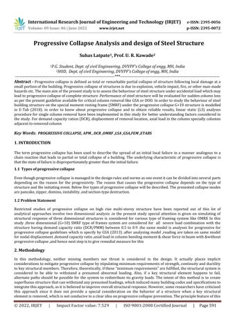
1.Analysisfortheinstantaneouslossofacolumnforonefloorabovegradelocatedatornearthemiddleoftheshortand longsideofthebuilding.
2.Analysisfortheinstantaneouslossofacolumnforonefloorabovegradelocatedatthecornerofthebuilding.
AnalyzefortheinstantaneouslossofacolumnForonefloorabovegradelocatedatornearthemiddleoftheshortsideof thebuilding.AnalyzefortheinstantaneouslossofaColumnForonefloorabovegradelocatedatorneartheMiddleofthe buildinglonglading.Analyzefortheinstantaneouslossofacolumnforonefloorabovegradelocatedatthecornerofthe building.
Figure 2.1 Plan view columns to be removed for assessment
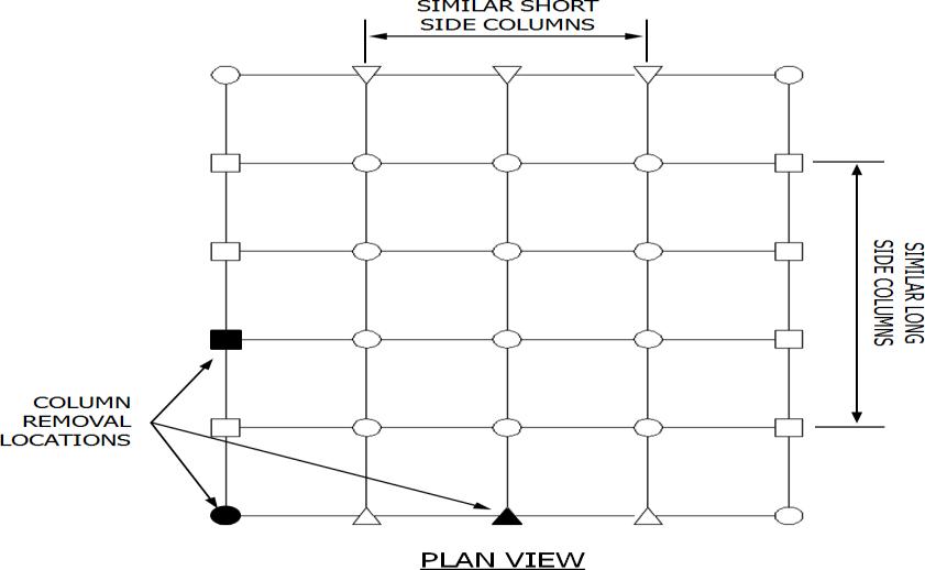
Facilities that have underground parking and/or uncontrolled public ground floor areas shall use the following interior analysiscase(s)intheprocedureoutlinedinAnalyzefortheinstantaneouslossof1columnThatextendsfromthefloorof theundergroundparkingareaoruncontrolledpublicgroundfloorareatothenextfloor(1story).Thecolumnconsidered shouldbeinteriortotheperimetercolumnlines.
International Research Journal of Engineering and Technology (IRJET) e ISSN: 2395 0056
Figure 2.2 Plan view showing column to be removed interiorly
ForaboveobjectiveasteelframedstructureismodelledinETABS2016softwarewithfollowingdetails
Table 3.1 Detail of Model Structures.
Type of structure Special moment resisting frame (SMRF)
Number of stories Ground +10
Location assumed Mumbai
Average wind speed 43m/s Soil type II
Live load for floor &terrace floor 2.5 KN/m2
Floor finish for floor &terrace floor 1.25 KN/m2
Wall load on beams 10 KN/m2
Concrete with unit weight 25 Steel with unit weight 77.008 Grade of steel used are Fy345Pa and E=200GPa Plan dimensions 40X40 and 4X4
Floor to floor height 3m
Height of the building 30m Slab thickness assumed 150mm Seismic zone Zone III
Importance factor 1
Response reduction factor 5
Section used BOX and I section
AccordingtoGSAnonlinearanalysisshouldbeperformedonhighrise(greaterthan10story)buildingsoastoconsiderthe effect of dynamic impact due to sudden loss of element in the structure.since the pushdown analysis is performed in the currentprojectwithdueconsiderationofP delta effect.asdiscussinthelastchapterAPMisthebestsuitablemethodfor analysisagainstPCunderremovalofprimarystructureelementononelevelatatime.
Generallyandasaminimumexternalcolumnsmustberemovalnearthemiddleoftheshortnearthemiddleofthelongside and at the corner of the building .columns must also be removal at location where the plan geometry of the structure changessignificantlysuchasabruptdecreaseinbaysizeandre entrantcornersoratlocationwhereadjacentcolumnsare lightly loaded the bays have different tributary sizes members frame in at different orientation or elevations and other
Volume: 09 Issue: 06 | June 2022 www.irjet.net p ISSN: 2395 0072 © 2022, IRJET | Impact Factor value: 7.529 | ISO 9001:2008 Certified Journal | Page593
International Research Journal of Engineering and Technology (IRJET) e ISSN: 2395 0056
Volume: 09 Issue: 06 | June 2022 www.irjet.net p ISSN: 2395 0072
similarsituation.inthecurrentstudyweremovedcolumnatcornermiddleofthelongerside,centrecolumnofthebuilding atdifferentfloorlocation.forthiswedecidedthatAPistakenongroundfifth,ninthlevels.astheresultsaverynegligible variation in the member due to it higher stiffness at the collapse part , AP is taken frequent level. For structure with underground parking or other uncontrolled public ground floor areas, it is also recommended that internal column be removed near the middle of short side, near the middle of the long side and at the corner of the uncontrolled space. the removed column extends from the floor of the underground parking area or uncontrolled public ground floor area to the nextfloor(i.e.aone storyheightmustberemoved)Internalcolumnsmustalsoberemovedatothercriticallocationwithin the uncontrolled public access area, as determined with engineering judgment. for both external and internal column removal continuity must be retained across the horizontal elements that connect to ends of the column The following figuresshowthepossiblelocationforthecolumnandtheareastobeloadedwithincreasedloadasperGSAguideline
Figure
The various parameters are compared before and after sudden column strength loss by different analysis. The results obtained are discussed with due consideration of cases. In this current study, we performed the progressive collapse analysis using GSA 2013 guidelines for this the sudden removal of any column due to any abnormal loads which are mentioned earlier in chapter 1. For this various cases performed as explain for various parameter and their graphs are plottedundersuddencolumnremovaleffecttostudythebehaviourofthemodelstructures.IftheDCRofthemembergoes beyond unity it shows red colour which means that particular member reaches its maximum strength (capacity). For the currentchapterallthecasesarecombinedforthepurposeofcomparisonsandgraphsareplottedandarementionunder thesametopic.Fortheeaseinunderstandingtheresultsaretakenonlyforcriticalmemberinthestructurewhichgivesthe bestresultsfortheprogressivecollapseloadcombinationwhichwasalreadydefinedinthemodelforanalysisanddesign againstPCaccordingtoGSA 2013
International Research Journal of Engineering and Technology (IRJET) e ISSN: 2395 0056
Volume: 09 Issue: 06 | June 2022 www.irjet.net p ISSN: 2395 0072
Case 1 :( C1) analysis for the sudden loss of a column situated at the corner of building
Case1.a:ColumnC1Removeatgroundfloor , Case1.b:ColumnC1Removeatfifthfloor Case1.c:ColumnC1Removeatninthfloor
Case 2: (C6) analyses for the sudden loss of a column situated at the middle of the one of the directions (X direction in this case) of the building
Case2.a:ColumnC6Removeatgroundfloor , Case2.b:ColumnC6Removeatfifthfloor Case2.c:ColumnC6Removeatninthfloor
Case 3: (C61) analyses for the sudden loss of a column situated at or near middle removal at any suitable location should be carried out for building .in these case column next to middle position.
Case3.a:ColumnC61Removeatgroundfloor, Case3.b:ColumnC61Removeatfifthfloor Case3.c:ColumnC61Removeatninthfloor
Case 1.b: Column C1 Remove at fifth floor
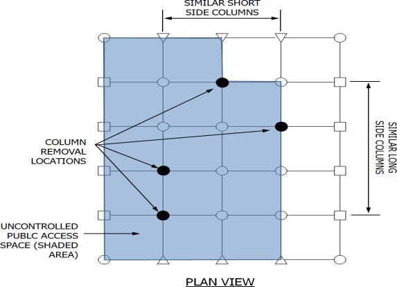
Table 4.1 Demand capacity ratio of column C1
Story Before PC After pc Remedial Diagonal Bracing 1 0.788 0.318 0.302 0.285 2 0.758 0.307 0.307 0.392 3 0.758 0.253 0.253 0.415 4 0.725 0.226 0.226 0.384 5 0.674 0 0 0 6 0.632 1.675 1.675 0.267 7 0.542 1.301 1.016 0.355 8 0.466 1.630 1.599 0.337 9 0.391 1.281 1.073 0.245 10 0.183 2.875 1.877 0.124
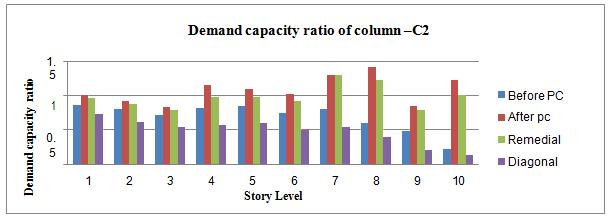
Table 4.2 Demand capacity ratio of column C2
Story Before PC After pc Remedial Diagonal Bracing
1 0.856 0.777 0.757 0.705 2 0.808 0.727 0.726 0.65 3 0.721 0.673 0.673 0.606 4 0.812 0.753 0.749 0.73 5 0.848 1.094 0.946 0.720 6 0.744 1.011 0.964 0.538 7 0.800 1.272 1.090 0.575 8 0.604 1.31 1.203 0.419 9 0.479 0.826 0.775 0.27 10 0.217 1.919 0.951 0.136
International Research Journal of Engineering and Technology (IRJET) e ISSN: 2395 0056
Volume: 09 Issue: 06 | June 2022 www.irjet.net p ISSN: 2395 0072
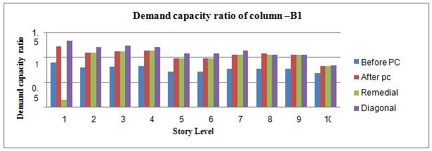
Table 4.3 Demand capacity ratio of column B1
Story Before PC After pc Remedial Diagonal Bracing
1 0.803 1.21 0.137 1.21 2 0.803 1.096 1.096 1.107 3 0.819 1.118 1.118 1.152 4 0.834 1.140 1.14 1.152 5 0.720 1.050 1.05 1.0135 6 0.720 0.983 0.883 0.983 7 0.772 1.056 1.056 1.055 8 0.772 1.055 1.055 1.055 9 0.772 1.059 1.06 1.055 10 0.685 0.834 0.834 0.835
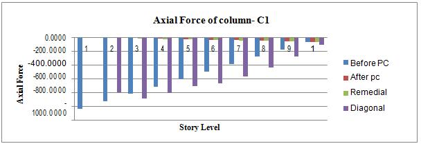
Table 4.4 Axial Force of column C1
Story Before PC After pc Remedial Diagonal Bracing 1 1040.5063 620.5856 623.5183 640.7281 2 931.0112 464.3895 464.3895 858.8703 3 821.5162 308.1935 908.1935 673.0237 4 712.2352 153.3979 153.3979 391.7032 5 606.1648 0 0 0 6 498.1661 9.5125 9.5387 286.7679 7 390.1673 21.9662 22.0184 394.3137 8 281.8779 35.4092 35.4862 366.7709 9 173.1885 48.6746 48.7914 237.2626 10 64.6991 62.127 62.102 88.7571
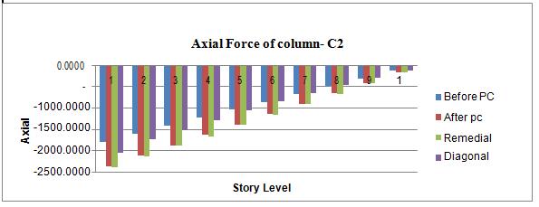
Table 4.5 Axial Force of column C2
Story Before PC After pc Remedial Diagonal Bracing
1 1781.7711 2114.036 2116.9064 2006.8265 2 1596.5924 1929.607 1929.5443 1833.3604 3 1411.41370 7545.1777 1745.1150 1710.0457 4 1225.89290 1560.26 1560.1974 1643.0009 5 855.78710 1375.3699 1375.3073 1236.2441 6 670.60330 1132.7407 1132.6885 915.4437 7 670.60330 891.1612 8091.1194 680.4272 8 486.94420 651.1035 651.0721 482.8928 9 302.79310 410.6449 410.624 294.4447 10 118.15350 169.788 169.7776 112.9428
International Research Journal of Engineering and Technology (IRJET) e ISSN: 2395 0056
Volume: 09 Issue: 06 | June 2022 www.irjet.net p ISSN: 2395 0072
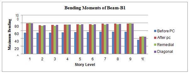
Table 4.6 Maximum Bending Moments of Beam B1
Story Before PC After pc Remedial Diagonal Bracing
1 54.4072 73.9029 75.2777 73.9029 2 54.4072 73.9029 73.9029 73.9029 3 55.0499 74.8208 74.8208 74.8208 4 55.6918 75.7407 75.7407 75.7404 5 56.4632 79.5636 79.5636 79.5636 6 56.4632 76.7669 76.7669 76.7669 7 57.0263 77.6292 77.6292 76.6292 8 57.0263 77.6292 77.6292 77.6292 9 57.0263 77.9292 77.6292 77.6292 10 36.4883 44.3425 44.3425 44.3425
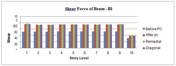
Table 4.7 Shear Force of Beam –B1
Story Before PC After pc Remedial Diagonal Bracing 1 51.4435 73.352 74.8784 73.352 2 51.4435 73.352 73.352 73.352 3 51.7856 73.8403 73.8403 73.8403 4 52.1259 74.3771 74.3271 74.3271 5 52.3247 76.1461 76.1461 76.1461 6 52.3247 74.6937 74.6926 74.6926 7 52.3011 74.8799 74.8799 74.8799 8 52.3011 74.8799 74.8799 74.8799 9 52.3011 74.8799 74.8799 74.8799 10 31.1945 39.2711 39.2711 29.2711
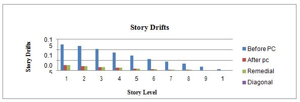
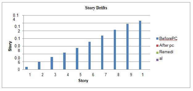
Table 4.8 Story Drifts
Story Before PC After pc Remedial Diagonal Bracing 1 0.006394 0.000331 0.000298 0.000065 2 0.019369 0.001333 0.00116 0.000056 3 0.031735 0.002364 0.002639 0.000028 4 0.042882 0.003489 0.003309 0.000061 5 0.055461 0.005115 0.004929 0.000267 6 0.071067 0.007516 0.007402 0.000187 7 0.087048 0.010396 0.010204 0.00021 8 0.102665 0.013907 0.013714 0.00015 9 0.117916 0.018690 0.018496 0.000138 10 0.125788 0.022670 0.022476 0.000142
International Research Journal of Engineering and Technology (IRJET) e ISSN: 2395 0056
Volume: 09 Issue: 06 | June 2022 www.irjet.net p ISSN: 2395 0072
a. Demand capacity ratio of column C1
b. Demand capacity ratio of column C2
c. Demand capacity ratio of column –B
International Research Journal of Engineering and Technology (IRJET) e ISSN: 2395 0056
Volume: 09 Issue: 06 | June 2022 www.irjet.net p ISSN: 2395 0072
International Research Journal of Engineering and Technology (IRJET) e ISSN: 2395 0056
Volume: 09 Issue: 06 | June 2022 www.irjet.net p ISSN: 2395 0072
InthiscaseweperformtheprogressivecollapseanalysisusingGSA 2013guidelinesforthisthesuddenremovalofany columnduetoabnormalload,inthisparticularcasethecornercolumnofthefirststorywasfailedthenthefailurepatterns ofstructurefromlocalfailuretoglobal failureAfterfailurestructureweareusingsameremedial toincreasesfailuretime i.e.decreasestheDCRi.e.completefailurewasinvested..Wecanuselinearstaticanalysis.TheDCRincreaseswhenremove columnC1at5st storyforlinearstaticwhichmeansstructurefailsatcolumnandbeamposition.
TheDCRistheratioofloadcomingontheelementtotheultimatecapacityoftheelement.Thestructurememberissafeif the DCR is below 1. And it said assumed failed when the ratio exceeds the limit of unity. Extent of damage can be quantifiable by observing the DCR values of members. DCR of adjoining structural members to removed column can be column are calculated using linear static method for column strength loss cases considered as per GSA guideline. Using remedialafterremovalofcolumnC1columntheDCRofcriticalcolumnischangedincaseofLSAanalysis.Thismeansafter usingremedialframesanddiagonalbracingarecapableoftakingloaduptocertainlimitbeforecollapse.Soitisconcluded thatremedialframeanddiagonalbracingarestrongerascomparedtonormalframe.Butascomparedtotheremedialand diagonalbracingsystemisstronger.Alsofromthegraph4.1(a,b&c)itisobservedthateffectofcolumnstrengthlosson thebeamgoondecreasingforbeamatupperlevelDCRvaluesforexteriorcolumnstrengthlossscenarioarelessbecauseof the fact that external beam contribute to less slab area as compare to internal beam. The change in bending moments of beamsobservedhelpstoconcludetheabovestatements.Thebendingmomentofbeamsgoondecreasingathigherlevels forthreecolumnstrengthlosscasesconsidered.HencetheDCRvaluesofbeamsgoondecreasing.Graph4.1(f)showsthe comparisonofbendingmomentswhencolumnstrengthlosstakesplaceatgroundlevel.Comparisonofmagnitudesofthe bending moment of beam immediate above removal column is summarized in table. It is observed that at near starting point of the beam, the shear force changes its nature and increases in magnitude whereas the shear force increases considerablyaftercolumnstrengthlosssuddenlybutdoesnotchangesitsnature.Thoughshearforcechangesitsnatureof
International Research Journal of Engineering and Technology (IRJET) e ISSN: 2395 0056
Volume: 09 Issue: 06 | June 2022 www.irjet.net p ISSN: 2395 0072
increasesconsiderablyaftercolumnstrengthlosssuddenlyitdoesnotleadtofailureofthemember,becausesectionsused havesufficientcapacitytoresistshearforceincreased.Ithasbeenobservedthatthereisno effectonshearforceofbeams forcolumnstrengthlossatdifferentlevel.Alsoweconcludedintheabovegraph4.1(d,e&f)thereIschangeinaxialforce and bending moment as inaxial force when weremoved the critical column there is drastic decrease in axial force at the criticalcolumnwhereasinothercolumnthereisincreaseinaxialforce.Whereasinbendingmomentcasethereisincrease inmomentinclockwisedirectionforalladjoinbeamsnearthecriticalcolumnlinearstaticanalysis.
Case 3.a: Column C61 Remove at fifth floor
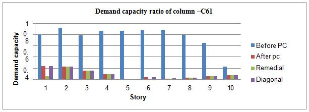
Table 4.9 Demand capacity ratio of column –C61
Story Before PC After pc
Remedial Diagonal Bracing
1 0.807 0.234 0.06 0.237 2 0.919 0.231 0.231 0.231 3 0.791 0.154 0.154 0.154 4 0.866 0.092 0.092 0.092 5 0.865 0 0 0 6 0.879 0.04 0.004 0.04 7 0.884 0.015 0.015 0.016 8 0.792 0.033 0.032 0.032 9 0.652 0.061 0.061 0.061 10 0.23 0.078 0.078 0.078
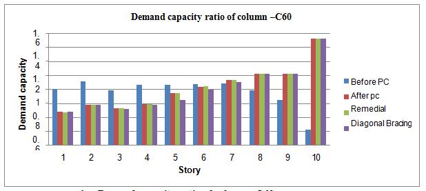
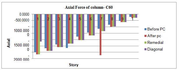
Table 4.10 Demand capacity ratio of column C60
Story Before PC After pc
Remedial Diagonal Bracing
1 0.807 0.481 0.476 0.481 2 0.919 0.577 0.577 0.577 3 0.791 0.527 0.527 0.523 4 0.866 0.586 0.586 0.578 5 0.865 0.751 0.751 0.648 6 0.879 0.84 0.841 0.798 7 0.884 0.934 0.934 0.906 8 0.792 1.024 1.024 1.024 9 0.652 1.021 1.021 1.021 10 0.23 1.522 1.522 1.522
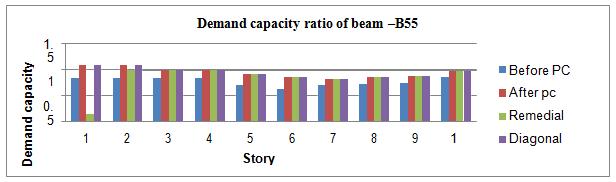
Table 4.11 Demand capacity ratio of beam B55
Story Before PC After pc
Remedial Diagonal Bracing 1 0.837 1.087 0.138 1.087 2 0.837 1.087 0.991 1.087 3 0.837 0.991 0.991 0.991 4 0.837 0.991 0.991 0.991 5 0.703 0.925 0.925 0.925 6 0.628 0.863 0.863 0.863 7 0.698 0.823 0.827 0.827 8 0.719 0.853 0.854 0.853 9 0.741 0.879 0.879 0.879 10 0.862 0.978 0.978 0.979
International Research Journal of Engineering and Technology (IRJET) e ISSN: 2395 0056
Volume: 09 Issue: 06 | June 2022 www.irjet.net p ISSN: 2395 0072
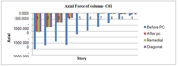
Table 4.12 Axial Force of column C61
Story Before PC After pc Remedial Diagonal Bracing
1 2991.8246 1551.5661 1591.7052 1551.5661 2 2680.3946 1162.4221 1162.4221 1162.4221 3 2370.7491 774.7057 774.7057 774.7057 4 2661.1036 386.9893 386.9893 386.9893 5 1752.3770 0 0 0 6 1443.5687 11.6407 11.6419 11.6405 7 1135.3963 37.4759 37.4752 37.4761 8 823.2353 62.521 62.521 62.5204 9 521.5664 87.1728 87.1714 87.1714 10 215.3916 111.8438 11.8443 111.8443
Table 4.13 Axial Force of column C60
Story Before PC After pc Remedial Diagonal Bracing
1 2991.8246 3162.5610 3160.7394 2162.561 2 2680.3946 2879.217 2879.217 2879.217 3 2370.7491 2597.3006 2597.3006 2597.3006 4 2661.1036 2315.3842 2315.3842 2315.3842 5 1752.3770 2034.1949 2034.1949 2037.1949 6 1443.5687 1677.3485 1677.2485 1677.2485 7 1135.3963 3224.4574 1324.4574 1324.4574 8 823.2353 972.4723 972.4723 972.4723 9 521.5664 620.8825 620.8825 620.8825 10 215.3916 269.6879 269.6879 269.6879
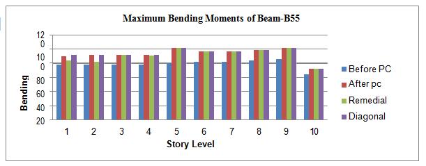
Table 4.14 Maximum Bending Moments of Beam-B55
Story Before PC After pc Remedial Diagonal Bracing
1 78.0415 90.0328 83.5049 92.0328 2 78.0415 92.0328 82.0328 92.0328 3 78.0415 92.0328 92.0328 92.0328 4 78.0415 92.0328 90.9017 92.0328 5 80.0351 101.2802 101.2802 101.2802 6 81.8833 96.7298 96.7298 96.7298 7 81.7979 96.6614 96.6614 96.6614 8 83.6553 98.975 98.975 98.975 9 85.5229 101.3081 101.3081 101.3081 10 63.9933 72.1602 72.1602 72.1602
International Research Journal of Engineering and Technology (IRJET)
e ISSN: 2395 0056
Volume: 09 Issue: 06 | June 2022 www.irjet.net p ISSN: 2395 0072
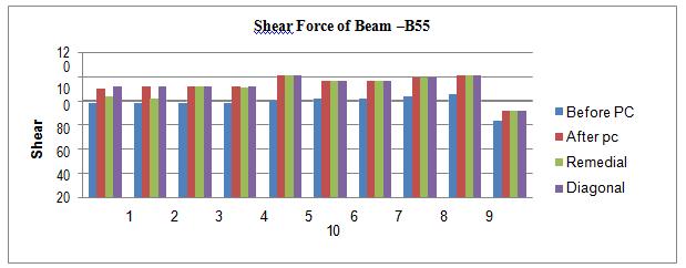
Table 4.15 Shear Force of Beam B55
Story Before PC After pc Remedial Diagonal Bracing 1 73.0370 90.4789 90.1722 90.4789 2 73.0370 90.4789 90.4889 90.4789 3 73.0370 90.4789 90.4749 90.4789 4 73.0370 90.4789 90.4789 90.4789 5 73.6920 95.0789 95.0789 95.0789 6 74.1606 92.203 92.223 92.223 7 74.0794 92.1501 92.1501 92.1501 8 74.5227 92.9347 92.9347 92.9347 9 74.9619 93.7076 93.7076 93.7076 10 53.0557 61.3736 61.3736 61.3736
Story Before PC After pc Remedial Diagonal Bracing 1 0.006394 0.000001 0.000001 0.000041 2 0.019369 0.000001 0.000002 0.000032 3 0.031735 0.000002 0.000002 0.0000014 4 0.042882 0.000004 0.000004 0.000003 5 0.055461 0.000004 0.000005 0.000006 6 0.071067 0.000005 0.000006 0.000008 7 0.087048 0.000008 0.000008 0.000011 8 0.102665 0.000009 0.000009 0.000001 9 0.117916 0.000011 0.000011 0.000012 10 0.125788 0.000014 0.000014 0.000016
a . Demand Capacity Ratio Of Column C61
International Research Journal of Engineering and Technology (IRJET) e ISSN: 2395 0056
Volume: 09 Issue: 06 | June 2022 www.irjet.net p ISSN: 2395 0072
International Research Journal of Engineering and Technology (IRJET) e ISSN: 2395 0056
Volume: 09 Issue: 06 | June 2022 www.irjet.net p ISSN: 2395 0072
International Research Journal of Engineering and Technology (IRJET) e ISSN: 2395 0056
Volume: 09 Issue: 06 | June 2022 www.irjet.net p ISSN: 2395 0072
InthiscaseweperformtheprogressivecollapseanalysisusingGSA 2013guidelinesforthisthesuddenremovalof any column due to abnormal load, in this particular case the corner column of the first story was failed then the failure patternsofstructurefromlocalfailuretoglobalfailurei.e.completefailurewasinvestigated.Afterfailurestructurewe are usingsame remedial to increases failure time i.e. decreases the DCR i.e. .complete failure was invested. We canuse linear static analysis. The DCR increases when remove column C61 at 5st story for linear static which means structure fails at columnandbeamposition.
TheDCRistheratioofloadcomingontheelementtotheultimatecapacityoftheelement.Thestructurememberissafeif the DCR is below 1. And it said assumed failed when the ratio exceeds the limit of unity. Extent of damage can be quantifiable by observing the DCR values of member s. DCR of adjoining structural members to removed column can be column are calculated using linear static method for column strength loss cases considered as per GSA guideline. Using remedialafterremovalofcolumnC61columntheDCRofcriticalcolumnischangedincaseofLSAanalysis.Thismeansafter usingremedialframesanddiagonalbracingarecapableoftakingloaduptocertainlimitbeforecollapse.Soitisconcluded thatremedialframeanddiagonalbracingarestrongerascomparedtonormalframe.Butascomparedtotheremedialand diagonalbracingsystemisstronger.Alsofrom thegraph4.2(a,b&c)itisobservedthateffectofcolumnstrengthlosson thebeamgoondecreasingforbeamatupperlevelDCRvaluesforexteriorcolumnstrengthlossscenarioarelessbecauseof thefactthatexternalbeamcontributetolessslabareaascomparetointernalbeam.
Thechangeinbendingmomentsofbeamsobservedhelpstoconcludetheabovestatements.Thebendingmomentofbeams go on decreasing at higher levels for three column strength loss cases considered. Hence the DCR values of beams go on decreasing.Graph4.2(f)showsthecomparisonofbendingmomentswhencolumnstrengthlosstakesplaceatgroundlevel. Comparison of magnitudes of the bending moment of beam immediate above removal column is summarized in table no.4.12
It is observed that at near starting point of the beam, the shear force changes its nature and increases in magnitude whereastheshearforceincreasesconsiderablyaftercolumnstrengthlosssuddenlybutdoesnotchangesitsnature.Though shearforcechangesitsnatureofincreasesconsiderablyaftercolumnstrengthlosssuddenlyitdoesnotleadtofailureofthe member,becausesectionsusedhavesufficientcapacitytoresistshearforceincreased.Ithasbeenobservedthatthereisno effectonshearforceofbeamsforcolumnstrengthlossatdifferentlevel.forcomparisonofalltheparametersTable5.77
Alsoweconcludedintheabovegraph4.2(d&e)thereIschangeinaxialforceandbendingmomentasinaxialforcewhen weremovedthecriticalcolumnthereisdrasticdecreaseinaxialforceatthecriticalcolumnwhereasinothercolumnthere isincreaseinaxialforce.Whereasinbendingmomentcasethereisincreaseinmomentinclockwisedirectionforalladjoin beamsnearthecriticalcolumnlinearstaticanalysis
1. From results it is conclude that the effect of progressive collapse in diagonal braced system is best as compared to increasethebeamandcolumnsizeatcriticallocationsystem.
International Research Journal of Engineering and Technology (IRJET) e ISSN: 2395 0056
Volume: 09 Issue: 06 | June 2022 www.irjet.net p ISSN: 2395 0072
2.Numberofstoryincreaseseffectofprogressivecollapsedecreasessincethenumberstomembersfortakingdistributed loadaremoreandhenceDCRvaluesofbeamsgodecreasingforupperlevelsbeamwhichshowsthemorefailureoccursin nearbyareaofremovedcolumn.
3.DCR valuesofbeamgo ondecreasingtowardsupper levelsbut DCR valuesofcolumngo onincreasingtowardsupper level.
4.Itisobservedthateffectofprogressivecollapsewasmorewhencornercolumnwassuddenlyremoved,asthenumber of story increases effect of progressive collapse decreases since the number of members for taking distributed load is more.
5.Itistheincreaseinbendingmomentofbeamduetoredistributionofloadingonremovedarealocationwhichleadsto failuremaybepartialorfullybutnotshearfore(strongcolumn&weakbeam)
6. Because of removal of column there is increase in load on the nearby column but loss of strength of same column on succeedinglevelsandsameeffectismorehazardouswhensuddencolumnlossoccursonhigherlevels
7. In any multi story high rise building stiffness and strength are more important so to stiffness and strength are more importantsotoimprovethischaracteristicofthestructureitispossibletoprovidebracing.
1. EngineeringResearchandApplications.Vol.2,Issue4,JuneJuly2012[2]
2. Jinkoo Kim† and Junhee Park “Design of steel moment frames considering progressive collapse”, Steel and CompositeStructures,Vol.8,No.1(2008)85 98[3].
3. Mojtaba Hosseini , Nader Fanaie and Amir Mohammad Yousefi “Studying the Vulnerability of Steel Moment Resistant Frames Subjected to Progressive Collapse”, Indian Journal of Science and Technology, Vol 7(3), 335 342, March2014.
4. M.A.Hadianfard,M.WasseghM.and SultanaMohammed.“Linearandnonlinearanalysisofprogressivecollapse forseismicdesignedsteelmomentframes.”14thinternationalconferenceoncomputingincivilandbuildingEngineering. Moscow,Russia27 29june2012.
5. Lawver,D.,H.Levine,andD.TennantResponseofReinforcedConcreteRoofandFloorSlabstoInternalExplosion for Ladeburg Bunker Test 10 10th International Symposium on Interaction of the Effects of Munitions with Structures, May2001.
6. Progressive Collapse Design Guidelines, Phase 1: Literature Search Department of State/Office of Foreign BuildingsOperations,Vols1 3,August8,1996.
7. AmericanSocietyofCivilEngineers(ASCE),MinimumDesignLoadsforBuildingsandOtherStructures,ASCE7 9
8. U.S.ArmyTechnicalManualTM5 1300StructurestoResisttheEffectsofAccidentalExplosions”.
9. Vaughan, D. K. FLEX User's Guide Report UG8298, Weidlinger Associates, Los Altos, CA, May 1983 plus updates through1997.
10. ANSYS,Inc.ANSYSUser’sGuide,Release5.5Canonsburg,PA,1994.
11. Hobbit,Carlson&Sorensen,Inc.ABAQUS/Explicit,Version6.1Pawtucket,RI,2000.
12. LARSA,Inc.,“LARSAWindowsSeries,”NewYork,NY,1997.
13. Mould, J. C., Jr. and H. S. Levine (1993), "A Rate Dependent Three Invariant Softening Model for Concrete," published in Studies in Applied Mech., Mech. and Materials and Structures, Ed. by G.Voyiadjis, L. Bank and L. Jacobs, Elsevier,1994.