International Research Journal of Engineering and Technology (IRJET) e ISSN: 2395 0056

Volume: 09 Issue: 06 | June 2022 www.irjet.net p ISSN: 2395 0072
International Research Journal of Engineering and Technology (IRJET) e ISSN: 2395 0056
Volume: 09 Issue: 06 | June 2022 www.irjet.net p ISSN: 2395 0072
2
1Student, Dept. of Mechanical Engineering, Gokul Global university, Gujarat, India 2Assistant Professor, Dept. of Mechanical Engineering, Gokul Global university, Gujarat, India ***
Abstract - The wind tunnel is one of the most common experimental testing facilities for the testing of fluid flow. The main aim of present work is to study effect of different configuration of wind tunnel on flow uniformity, flow separation and pressure gradient.Thisprojectaimstopropose the different configuration for wind tunnel design using CFD tool and investigated experimentally. The contraction, test section and diffuser section were studiedandliteratureisdone to propose modified design numerically using CFD tool and validating it experimentally..
Keywords: Wind tunnel,Diffuser, Test section, Contanction ratio, CFD
Even with today's computers, a wind tunnel is still an essential engineering tool for model tests, basic experimentalresearchandcomputercodevalidation.Since the193Os,whenthestrongeffectoffree streamturbulence on shear layer behaviour became apparent, emphasis has beenlaidonwindtunnelswithgoodflowuniformityandlow levelsofturbulenceandunsteadiness.Inthepast,ithasbeen difficulttodevisefirmrules forwindtunnel designmainly duetothelackofunderstandingofflowthroughthevarious tunnel components. The first attempt at providing some guidelinesforthecompletedesignoflow speedwindtunnels wasthatduetoBradshawandPankhurst(1964).However, recent experimental studies of flow through individual componentsofawindtunnel(Mehta,1977,1978andMehta andBradshaw,1979)haveled to increased understanding anddesignphilosophyformostofthecomponentswiththe notableexceptionofcontractions.
Thefirst flowexperimentsarosearound1700usingsmall fanswithatestobjectinfrontofit(PopeandHarper,1966). The fans gradually expanded to wind tunnels by adding more parts, such as a closed test sections and flow straighteners, to the design. In the 20th century, they got into the shapes as they are known nowadays. Alongside wind tunnels, computers started to gain popularity in the 1970’sand80’s.Itwasexpectedthatcomputersimulations wouldsoonreplacethewindtunnelexperiments(Barlowet al.,1999,Moonenetal.,2006a).However,uptothisdatethe physics of turbulent flows is not yet fully understood. Therefore computational data are simplifications of the
reality and wind tunnel studies are needed to validate models.
1 Study of different contraction design of wind tunnel for betterperformancebyusingCFD
Todesignwindtunnelwithgoalsillustratedasbelow
A)flowuniformityintestsection.
B)absenceofflowseparation(controllingPressureGradient intheContraction).
2 Re Designingcontractionshapeusingnumericalmethod andfindingoptimumshapeusingCFDsimulation.
3 Investigatingeffectofplacementoftripwirescreenonthe pressuredistributionincontraction.
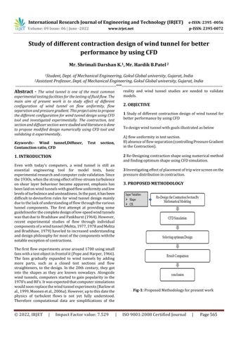
Fig-1: ProposedMethodologyforpresentwork
International Research Journal of Engineering and Technology (IRJET) e ISSN: 2395 0056
Volume: 09 Issue: 06 | June 2022 www.irjet.net p ISSN: 2395 0072
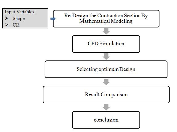
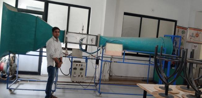
Theexistingwindtunnelfacilitypresentedinthisworkisan opencircuittypedrivenbyvariablespeedcontrolledaxial fan placed at the end of diffuser section with following configuration
Table 1: Windtunnelsetupconfiguration.
Bell mouthInlet crosssection 90cmX90cm
ContractionInlet crosssection 70cmX70cm
testsectioninlet /Contractionoutlet 30cmX30cm
CR(Contraction Ratio) 9
Lengthofcontraction 130cm
Testsectionlength 100cm Diffuserlength 200cm Diffuseroutlet diameter 54cm
Airflowspeedrange 0 25m/s Suctionmotor 2.30kw(3Hp)
FromBernoulli’sEquation
P1+½��V12 =P2+½��V22
But,V2=Stagnationpointvelocity=Zero
So,P2 P1=½��air V12 V1 = ΔP=P2 P1=��water*g*Δh V1=
SampleCalculation:Velocity: 20m/s V1= V1= V1=20.08m/s
Fig 2: OpencircuitWindTunnelSetup.
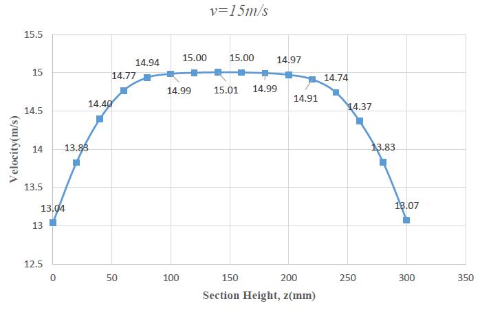
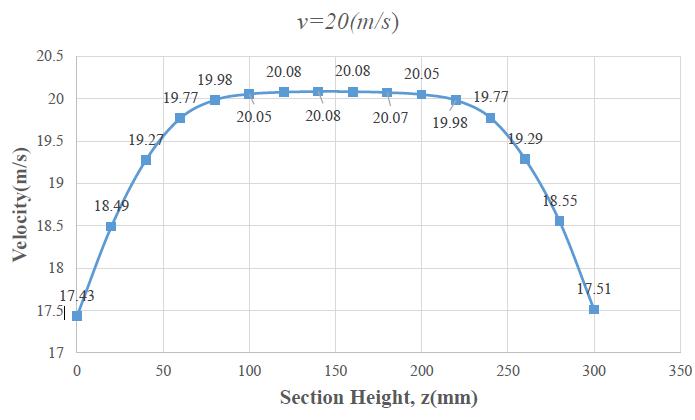
Fig 3: Velocitiesatdifferenttestsectionheightfor v=20m/s.
Fig 4: SectionalVelocitydistributionforv=15m/s.
International Research Journal of Engineering and Technology (IRJET) e ISSN: 2395 0056
Volume: 09 Issue: 06 | June 2022 www.irjet.net p ISSN: 2395 0072
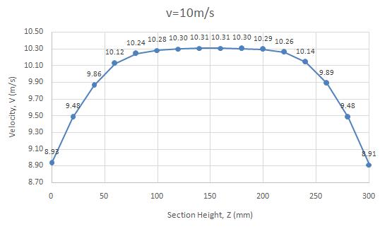
Fig-5: SectionalVelocitydistributionforv=10m/s.
Table-2: Uncertainityofpitottubemeasurement.
Anemometer velocities(m/s)
Pitot tube velocity (m/s) % error 5 2.186 3.72 10 10.3306 3.306 12.9 13.0198 0.9286 14.2 14.0630 +0.97717 17.2 16.8085 +2.2762 19 18.5128 +2.5642 20 19.4031 +2.9845
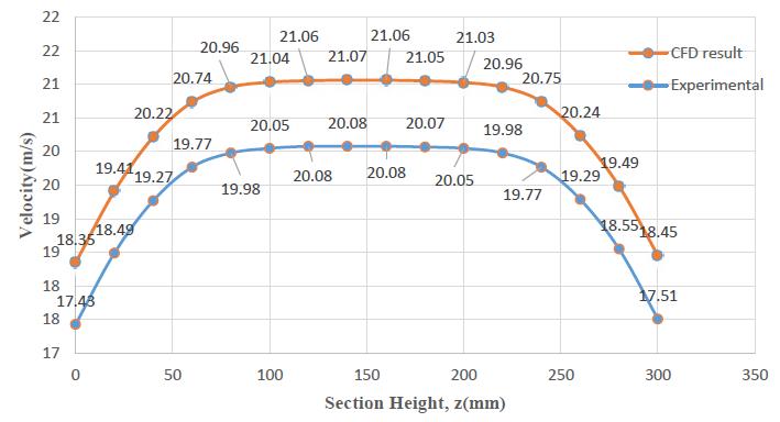
CFDmodelisgeneratedbyapplyingboundariesconditions suchthatatmid sectionoftestsectionwegetatmospheric pressure and desired velocity assuming temperature and density ofair remains unchanged. Andresultis compared withexperimentaloneasshowninfigure1.9andfoundthat CFDpredictssomewhathighvalueofvelocitythroughoutthe sectionanditissobecauseinmodelwehavenotconsidered atrip stripplacedinbell mouthofsetupwhichofferssome pressuredrop.
Fig 6: ExperimentalandCFDVelocityresultcomparison.
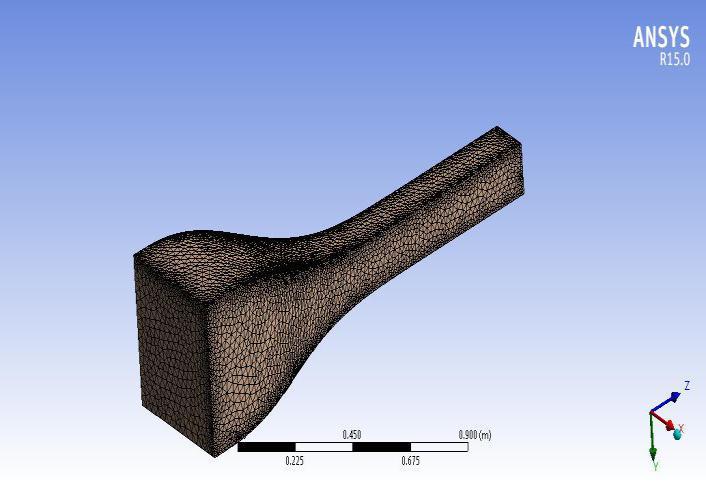
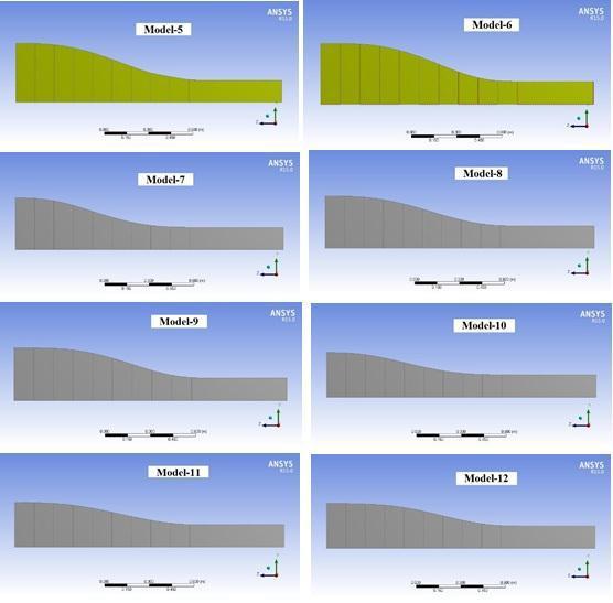
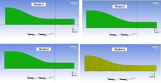
Fig-7: 3DModels
Fig-8: Meshedmodel
International Research Journal of Engineering and Technology (IRJET) e ISSN: 2395 0056
Table 3: No.ofnodesandelementsofmeshedmodel
MeshMethod Nodes Elements
Tetrahedron 18054 87067
Fig-11: Wallshear(Pa)plot
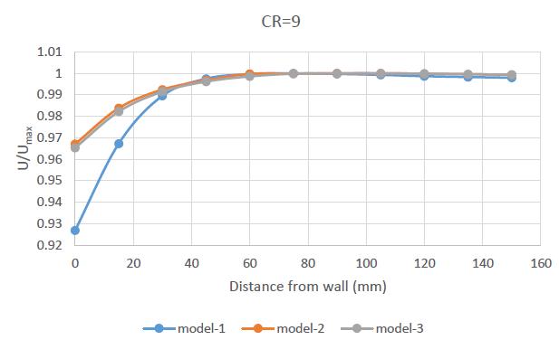
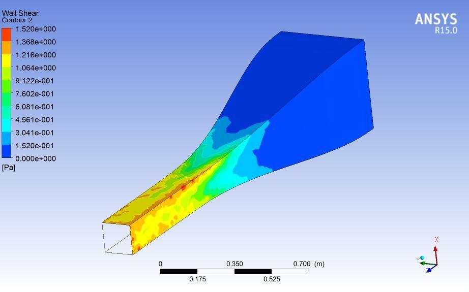
Fig 9: BoundaryconditionsappliedtomodelinANSYS CFX.
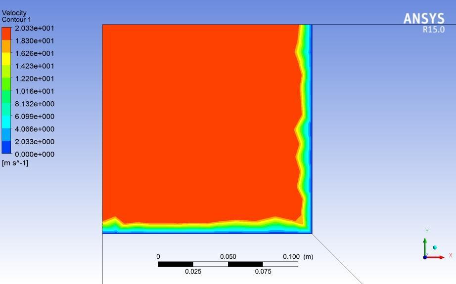
Figure5 showsinlet,outletboundaryconditionsbyarrows, andwallboundarybygreyandsymmetryboundarybyblue colour. And the conditions applied to every boundaries is summarised in above report exported by ANSYS. The ReynoldsShearStressTransport(SST)modelofturbulence wasusedwithaspecifiedturbulencelevelof1%.
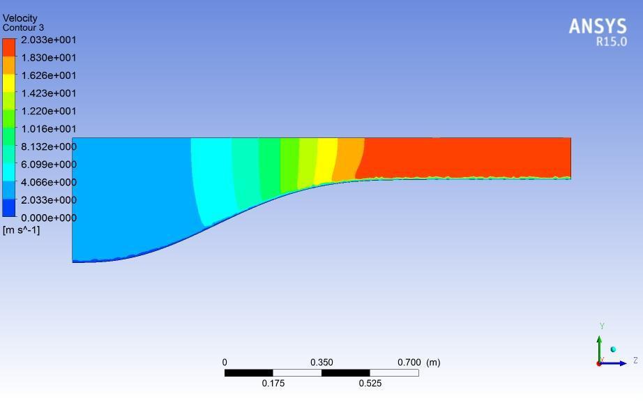
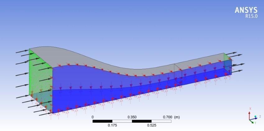
Fig-12: Velocitycontouratmid planeofcontraction
Fig 10: Velocitydistributionatmid testsection
Volume: 09 Issue: 06 | June 2022 www.irjet.net p ISSN: 2395 0072 © 2022, IRJET | Impact Factor value: 7.529 | ISO 9001:2008 Certified Journal |
International Research Journal of Engineering and Technology (IRJET) e ISSN: 2395 0056
Volume: 09 Issue: 06 | June 2022 www.irjet.net p ISSN: 2395 0072
Fig 13: Velocityprofileatmidworkingsectionon horizontalplane
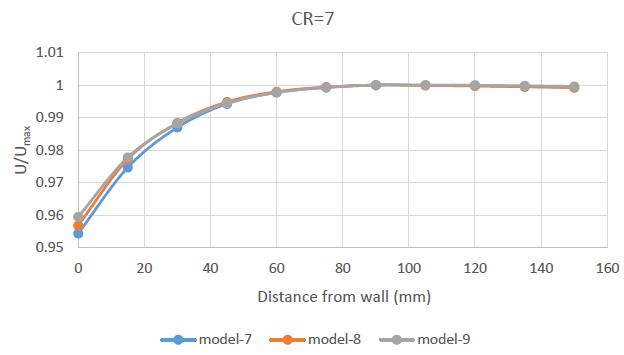
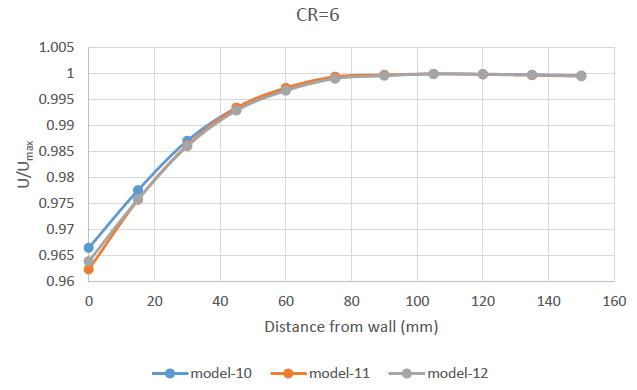
Fig-14: Optimummodelsfromalltwelvemodels
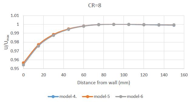
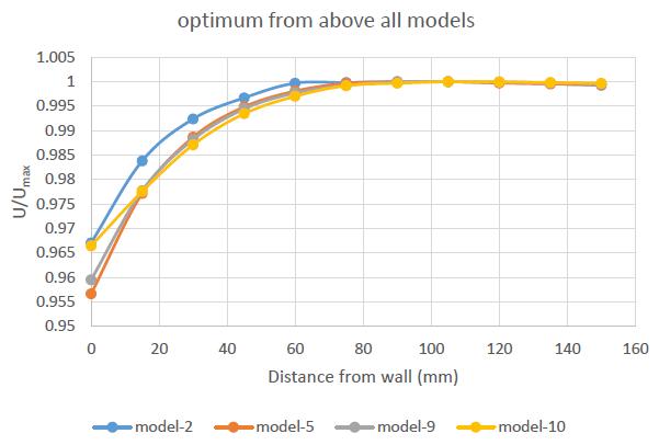
CFDhasbeenusedtooptimizethedesignofawindtunnel contraction.TheuseofCFDhas increased the flexibility of shapes considered, and allowed the use of a sixth order polynomialtodefinetheprofile.Theparametersoftheprofile thatwerevariedwerethelocationofthepointofinflection andtheContractionRatio.TheCR6isusedandcontraction fabricatedisofrectangular to squaretypenow.Resultsshow thatthegeneralbehavioroftheflowintheregionsawayfrom the wall is in reasonable agreement with the predicted behavior.Velocityuniformitygetdisturbedatcorners.Andat wallsitdeviatesfromCFDresultsthissobecausewehave considered smooth wall which is impractical. Physical calibrationofthefacilityhasvalidatedtheCFDmethodsused anddemonstratedthatthetechniquecanbeusedforfuture windtunneldesigns.
Further work can be done to know effect of placement of mesh screenlikehoneycombatinletofcontractionmouthon velocityuniformity.Evenonecanworkbyplacing guiding channel in inlet contraction to make flow parallel in test sectionmentionedinliterature.
[1]Ismail,JohanisJohn,ErlandaA.Pane,BudhiM.Suyitno, Gama H.N.N. Rahayu , Damora Rhakasywi ,Agri Suwandi “Computationalfluiddynamicssimulationoftheturbulence modelsinthetestedsectiononwindtunnel”(2020)
[2]JiaoLei,PengchengHuang,LinheZhang,YukuiYuan, Wenyang Deng , Shaohua Mao, Jun Zhang “Experimental studyonflowcharacteristicsofalarge scaleopenjetwind tunnelforoutdoorpoolfireresearch”(2021)
[3]HaoSu,HaoranMeng, TimingQu,LipingLei “ Wind tunnelexperimentontheinfluenceofarrayconfigurationon thepowerperformanceofverticalaxiswindturbines”(2021)
International Research Journal of Engineering and Technology (IRJET) e ISSN: 2395 0056
[4] Leifur Leifsson, Slawomir Koziel “Simulation driven designoflow speedwindtunnelcontraction”(2015)
[5] Keum Yong Park, Yeol Hun Sung, Jae Hung Han, “Developmentofacablesuspensionandbalancesystemand itsnovelcalibrationmethodsforeffectivewindtunneltests”, (2020)
[6] GuiquanFu,XianyingXu,XiaonaQiu,GaoxingXu,Wen Shang,XuemeiYang,PengZhao,ChengwuChai,XiaokeHu, Yunian Zhang, Qiangqiang Wang, Chuanyan Zhao, “Wind tunnel study of the effect of planting Haloxylon ammodendrononaeoliansedimenttransport”,(2021)
[7] WeiYi, PengZhou, YiFang, JingwenGuo, SiyangZhong, XinZhang,XunHuang,GuochengZhou,BaoChen,“Designand characterization of a multifunctional low speed anechoic windtunnelatHKUST”,(2021)
[8] A.S.Abdelhamed,Y.El S.Yassen,M.M.ElSakka,“ Design optimizationofthreedimensionalgeometryofwindtunnel contraction,(2014)
[9] María Rodríguez Lastra , Jesús Manuel Fernández Oro,Mónica GaldoVega, Eduardo Blanco Marigorta, Carlos SantolariaMorros , “Novel design and experimental validation of a contraction nozzle for aerodynamic measurementsinasubsonicwindtunnel”,(2013)
[10]LingJin,YunsongGu,XiaoBingDeng,HaishengSun, TingruiYue,JunlongZhang,“Standingwaveanditsimpact on the low frequency pressure fluctuation in an open jet windtunnel,(2020)
[11] Roberto Merino Martínez , Alejandro Rubio Carpio , LourençoTércioLimaPereira,StevevanHerk,Francesco Avallone , Daniele Ragni , Marios Kotsonis, “Aeroacoustic design and characterization of the 3D printed, open jet, anechoic wind tunnel of Delft University of Technology”, (2020)
[12] Ismail , Johanis John , Erlanda A. Pane , Budhi M. Suyitno , Gama H.N.N. Rahayu, Damora Rhakasywi , Agri Suwandi,“Computationalfluiddynamicssimulationof the turbulence models in the tested section on wind tunnel”, (2020)
[13] HrvojeKozmar,BorisLaschka,“Wind tunnelmodeling of wind loads on structures using truncated vortex generators”,(2019)
[14] J.McCarthy,T.Teske,S.Lam,M.Jones,“Preliminary assessmentofsurfacepressuremeasurementsonametallic, additivemanufacturedwindtunnelmodel”,(2020)
[15] W.C.Niu,Y.L.Ju,“ Systemdesignandexperimental verificationofaninternalinsulationpanelsystemforlarge scalecryogenicwindtunnel”,(2021)
Volume: 09 Issue: 06 | June 2022 www.irjet.net p ISSN: 2395 0072 © 2022, IRJET | Impact Factor value: 7.529 | ISO 9001:2008 Certified Journal | Page570