International Research Journal of Engineering and Technology (IRJET) e ISSN: 2395 0056

Volume: 09 Issue: 06 | June 2022 www.irjet.net p ISSN: 2395 0072
International Research Journal of Engineering and Technology (IRJET) e ISSN: 2395 0056
Volume: 09 Issue: 06 | June 2022 www.irjet.net p ISSN: 2395 0072
1PG Scholar,Department of Civil Engineering,Dr.D.Y.Patil School of Engineering and Technolgy, Charholi Bk, Via Lohegaon, Pune, Maharastra, India
2Associate Professor, Department of Civil Engineering, Dr.D.Y.Patil School of Engineering and Technolgy, Charholi Bk, Via Lohegaon, Pune, Maharastra, India ***
Abstract As the world's population grows, so does the cost of accessible land. The lateral loads become more important than the gravitational loads as the building's height rises. Wind load and earthquake load are two forms of lateral loads that can be applied to high rise buildings. Different forms of lateral load resisting structures used in high rise buildings include shear walls, rigid framed structures, brace tubes, wall frames, outrigger systems, and diagrid systems.
For lateral load resistance, thediagridstructuralsystem isan efficient and effective structural system. Diagrid structure isa type of exterior structural system in which all external columns are replaced by a sequence of triangular shaped diagonal grids, and inside columnsaresolelymeanttosupport gravity loads.
Two forms of 48 story structures in seismic zone III are studied in this study: rectangular&L shape.Thetotalheightof all the structures is 168 meters. There are four diagrid modules in the seismic zone. In the diagrid construction, two, four, six, and eight modules have been employed. E TABS is used to analyses and simulate diagrid structure. IS 800:007 is used to design all structural members. For earthquake analysis, IS 1893 part1 2016 is utilized, and for wind load analysis, IS 875 part3 2015 is employed. For dynamic analysis, the response spectrum approach is used. The maximum storey displacementandmaximumstoreydriftof all the study findings are compared, and the ideal diagrid angle for all modules is calculated.
Key Words: Diagrid structure, Storey displacement, Storey drift, Optimum diagrid angle
Rapid population expansion and high land costs have a significantinfluenceontheconstructionsector,whichleads toanupwardtrendinbuildingconstruction.However,when buildingheightsrise,lateralloadresistingsystemsbecome morecriticalthangravityloadresistingstructuralsystems. To withstand the lateral stresses. Rigid frame, shear wall, wall frame,utilised braced tubesystem,outriggersystem, andtubularsystemaresomeofthemostprevalentsystems. Because of the structural efficiency and aesthetic possibilities given by the system's distinctive geometric design, the diagonal grid structural system has recently
become popular for tall structures. Rapid population expansionandhighlandcostshaveasignificantinfluenceon theconstructionsector,whichleadstoanupwardtrendin buildingconstruction.However,whenbuildingheightsrise, lateral load resisting systems become more critical than gravity load resisting structural systems To be able to toleratelateralstrains.Someofthemostcommonsystems includerigidframe,shearwall,wall frame,employedbraced tube system, outrigger system, and tubular system. The diagonalgridstructuralsystemhaslatelybecomepopular for tall structures due to its structural efficiency and aestheticpossibilitiesprovidedbythesystem'sdistinctive geometric form. Because of the layout and efficiency of a diagridsystem,thenumberofstructuralelementsrequired ontheoutsidesideofbuildingsisreduced,resultinginless blockagetotheoutsideview.Thestructuralefficiencyofthe diagrid system also aids in the avoidance of interior and cornercolumns,allowingforgreatfloordesignfreedom.The most recent high rise building system, which has now becomethemostpopularThe"DiagonalGridSystem,"also known as the "Diagrid system," is popular among today's designers. The Diagrid system is made up of multiple diagonalcomponentsthatjointoproduceatriangulatedor grid shapeddesign.Thename"diagrid"isderivedfromthe phrases"diagonal"and"grid."Adiagridstructureisasortof structuralsystemthatconsistsofdiagonalgridsconnected by horizontal rings to provide a beautiful and redundant structurethatisparticularlyusefulforhigh risestructures. Due to its triangulated configuration, diagrid structures differ from braced frame systems in that diagonals as key structuralcomponentscontributeinsupportinggravityload aswellaslateralload,obviatingtherequirementforvertical columns. A diagrid system's column free structure has variousadvantages,includinggreatarchitecturalfreedom, elegance,andhugedayilluminationduetoitssmalloutside surface. Because of its structural efficiency, the diagrid system has recently been used on numerous tall steel structures.
I. To assess the performance of a high rise building equippedwithadiagridsystem.
II. Todostaticanalysis,responsespectrumanalysis, and wind analysis in terms of story displacement anddrift
International Research Journal of Engineering and Technology (IRJET) e ISSN: 2395 0056
Volume: 09 Issue: 06 | June 2022 www.irjet.net p ISSN: 2395 0072
III. Determine the diagrid system's optimal diagrid angle.
Structural parameter Steel structure
Shapesofbuilding rectangularandL shape
Numberofstories 48
Sizeofplan a).forrectangularshape 48mx64m b).forL shapeshape 48mx48m
Spacingbetweenbays 4m
Spacingbetweendiagridalong perimeter 8m
Heightofeachstorey 3.5m
Numberstoreypermodule 2,4,6,&8storey
Gradeofstructuralsteel(Fy) Fe500
Gradeofconcrete(Fck) M40
Case I:Comparisonbetweeneachmoduleforrectangular andL shapeshapeofstructure.
2 storeymodule
4 storeymodule
6 storeymodule
8 storeymodule
Case II:CombinationallstoreymodulesrectangularandL shapeofstructure.
2 storey,4 storey,6 storeyand8storey
Theanalysisofa48 storydiagridstructurewithrectangular andL shapedbuildingisofferedinthiswork.AsperIndian Standard, lateral forces owing to earthquakes and wind effectsaretakenintoaccount.Thestructurewasanalyzed usingIS1893:2016andIS800:2007.TheETABSprogramme is used for modeling and analysis of diagrid systems. Earthquake loads are subjected to response spectrum analysis. The beams and columns are treated as flexural components for linear static and dynamic analysis. The majorgoalofthisstudyistoinvestigatethebehaviorofhigh
rise buildings with Diagrid systems of various angles for rectangular and L shape structures in seismic zone III, as well as to determine the best diagrid angle using static, dynamic,and windanalysis. Infirstphase,modelingof48 storeyhighrisebuildingswithDiagridsystemsbydefining materialandsectionproperties&havingsameheightwith different diagrid angles which is done by using ETABS software.
In second phase, define several sorts of loads and their combinationsontherectangularshapeofthestructureinthe second phase. Define the functions necessary for the response spectrum in dynamic analysis. Finally, using the findings of the study, verify the behavior of a rectangular shapestructurewithDiagridsystemsofthesameheightand differentangleinseismiczoneIII.
In third phase, define several sorts of loads and their combinationsonadditionalL shapestructuresfordynamic analysisinthethirdphase.Definethefunctionsthatwillbe used to create the response spectrum. Finally, using the findingsofthestudy,examinethebehavioroftheL shapeof structure with Diagrid systems with the same height and differentangleinseismiczoneIII.
In fourth phase, Thecollecting andanalyzing data on two formsofstructuresintheformofseveralparameterssuchas StoreyshearandStoreyDriftisthefourthphase.
In the fifth step, evaluate all seismic zone III factors to determine the best angle for rectangular and L shaped structures, as well as combinations of 2, 4, 6, and 8 story modules.
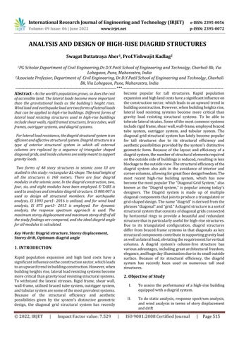
Fig 1:Planofrectangularshapebuildingmodel
Figure1showsthetypicalplanofrectangularshapebuilding models which are Considered for the study as shown in figureandspacingbetweeneachbayis4meters.
2022, IRJET | Impact Factor value: 7.529 | ISO 9001:2008 Certified Journal |
International Research Journal of Engineering and Technology (IRJET) e ISSN: 2395 0056
Volume: 09 Issue: 06 | June 2022 www.irjet.net p ISSN: 2395 0072
Fig 2:PlanofL shapebuildingmodel
ThebuildingissubjectedtofollowingLoadsasperIS875 (part1and2) 2015:
Deadload:2kN/m2 LiveLoad:3kN/m2
Thefollowingtableshowsthatbasicdesignconsiderationin seismiczoneIII.
Zone Zone factor Location of building
Basic wind speedof cityin m/s
Soiltype
III 0.16 Pune 39 Hard(site type1)
Table 1: Basicdesignconsideration
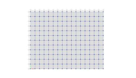
Fig 3: 3Drenderedviewofrectangularshapestructure
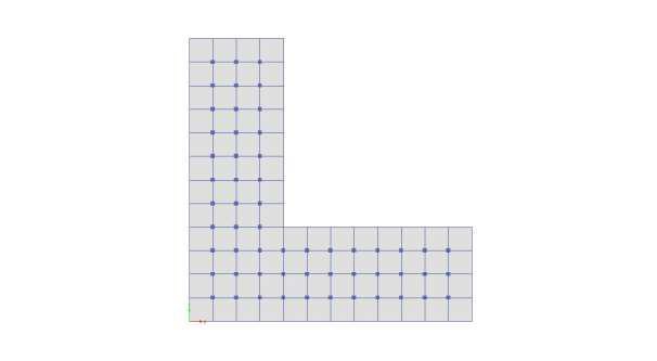
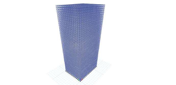
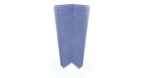
Fig 4: 3DrenderedviewofL shapestructure
Story Beam Column [tube section]
Diagrid [pipe section] 1 16 ISMB550 750X750X 50 750X25 17 32 ISMB500 700X700X 45 750X25 33 48 ISMB500 600X600X 35 750X25
Table 2: Section propertiesforrectangular&L shapeof building
Numberstoreysper module Angle (Degree) 2 41.18 4 60.25 6 69.14 8 74.05
Table 3:Diagridangleforrectangular&L shapeof building
DuringtheseismiczoneIIInarrativemoduleanalysis, all loadcombinationsarechosenasperIS800 InETABS,the loadcombinationsshowninthetableareselectedusingthe defaultsteelstructurecombination.
Windparameterdetails:(ASPERIS875 2015)inzoneIII.
Terraincategory 3 Structureclass C Riskcoefficient 1.06
Topographyfactor 1 Importancefactor 1.30
2022, IRJET | Impact Factor value: 7.529 | ISO 9001:2008 Certified Journal
International Research Journal of Engineering and Technology (IRJET) e ISSN: 2395 0056
Volume: 09 Issue: 06 | June 2022 www.irjet.net p ISSN: 2395 0072
1.AnalysisResultanditsDiscussionfor Rectangular shape ofbuildinginSeismicZoneIII.
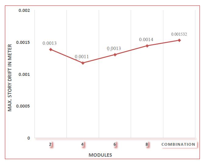
Fig 6:Maximumstoreydriftforallmodulesin rectangularshapestructure
2.AnalysisResultanditsDiscussionfor L-shape of building inSeismicZoneIII.
Fig 5:Maximumstoreydisplacementforallmodules modulesinrectangularshapestructure
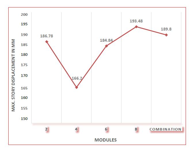
The graphical representation of maximum storey displacement of 48 story rectangular building modules in zoneIIIisshowninFigure:5.Inthe8modulediagrid,the maximumstoreydisplacementis193.48mm.Thegreatest storeydisplacementwiththeleastvalueis166.2mm,which isrecordedforafour storymodule.Theminimumvalueof maximum story displacement is found to be between 60 degree and 70 degree. The maximum allowable storey displacement is 336 mm, When comparing eight module diagridtofourmoduleandsixmodulediagrid,themaximum storydisplacementforfourmoduleandsixmodulediagridis reducedby14.09%and4.46% respectively.
Themaximumstoreydriftof48storyrectangularbuilding modulesinzoneIIIisdepictedgraphicallyinFigure:6.Thisis thegraphicalrepresentationforwindloadanalysisbecause, whencomparedtoseismicandresponsespectrumanalysis, windloadanalysisoffersthehighest valuesoftaledriftin zoneIII.Themaximumstoreydriftinthecombomoduleis 0.001532m,whichisgreater.Thesmallestmaximumstorey driftvalueis0.001176m,whichmaybefoundinthefour storymodulediagrid.Themaximumallowablestoreydriftis 0.014m MaximumstorydriftforallmodulesinzoneIIIis observed to be within this limit. Maximum story drift for fourmoduleandsixmodulediagridisreducedby23.24% and 15.68% when we compare with combination module diagridwhichgivesmaximumvalueofdriftinzoneIII.
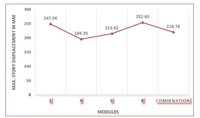
The maximum storey displacement of 48 storey L shaped buildingmodulesinzoneIIIisdepictedgraphicallyinFigure 7. In 8 modules, the maximum storey displacement is 252.65mm.194.35isthesmallestfigureofmaximumstorey displacement mm, which may be seen in a four story module.Ithasbeendiscoveredthattheminimumvalueof maximumstoreydisplacementrangesfrom60to70degree Thehighestallowablestoreydisplacementis336mm,and allmodulesinzoneIIIhavemaximumstorydisplacements thatarewithintheallowablelimit. Whenwecomparethe maximumstorydisplacementofeightmodulediagridtofour andsixmodulediagrid,themaximumstorydisplacementof fourandsixmodulediagridisloweredby23.07%and15.44 %respectively.
International Research Journal of Engineering and Technology (IRJET) e ISSN: 2395 0056
Volume: 09 Issue: 06 | June 2022 www.irjet.net p ISSN: 2395 0072
(1).M.M.AliandK.Moon.(2007).Structuraldevelopments in tall buildings: Currents trends and future prospects. ArchitecturalScienceReview,UniversityofSydney.
(2).BerryCharnishandTerryMcDonnell.(2008).TheBow: Unique diagrid structural systems for a sustainable tall building.CTBUH20088thWorldCongress,Dubai.
(3). K. S. Moon. (2011). Diagrid Structures for Complex ShapedTallBuildings.The12thEastAsiaPacificConference onStructuralEngineeringandConstruction.
Fig 8:MaximumstoreydriftforallmodulesinL shape structure
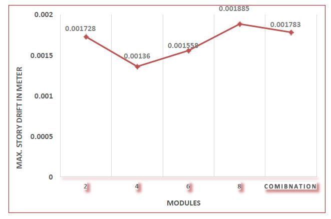
The maximum storey drift of 48 storey L shaped building modulesinzoneIIIisdepictedgraphicallyinFig8.Inthe8 module diagrid, the maximum storey drift is 0.001885 m. The smallest maximum storey drift value is 0.001360 m, whichmaybefoundinThediagridisafour storymodule. The maximum allowable storey drift is 0.014 m, and maximumstorydriftforallmodulesinzoneIIIisobserved to be within this limit. When eight module diagrid is compared to four and six module diagrid, the maximum narrativedriftforfourandsixmodulediagridisloweredby 27.85%and17.34%respectively.
i).Windloadhasthemaximumstorydisplacementandstory driftinrectangularandL shapedbuildingsascomparedto earthquakeload.
ii).8 storey diagrid module has the maximum story displacement and story drift in rectangular and L shaped buildings.
iii).Combination of all modules in rectangular building producesminimumvalueofmaximumstoreydisplacement andmaximumstoreydriftthanL shapeofstructure.Inthe 60 70 degree range, maximum storey displacement and maximumstoreydriftdecrease.
iv). In comparison to 2 storey, 6 storey, and 8 storey modules, the 4 storey module in any form of building delivers less value of maximum storey displacement and maximumstoreydrift.
(4).K.JaniandPareshV.Patel.(2013).Analysisanddesign of diagrid structural system for high rise steel buildings. Chemical, Civil and Mechanical Engineering Tracks of 3rd NirmaUniversityInternationalConferenceonEngineering. (5)G.Milana,P.Olmati,K.GkoumasandF.Bontempi.(2014). Sustainabilityconceptsinthedesignofhigh risebuildings: thecaseofdiagridsystems.3rdInternationalWorkshopon DesigninCivilandEnvironmentalEngineering.
(6).F.M.Thomas,BinuM.IssacandJessymolGeorge.(2015). Performanceevaluationoftallbuildingswithsteeldiagrid system. 2nd International Conference on Science, TechnologyandManagement.
(7). Manthan Shah, Snehal V. Mevada and Vishal B. Patel. (2016). Comparative study of diagrid structures with conventional frame structures. International Journal of EngineeringResearchandApplication.
(8).Dr.MohammadTBhuiyanandDr.RobertoLeon.(2016). Preliminary design of Diagrid tall building. IAJC ISAM InternationalConference.
(9). U. A. Nawale and D. N. Kakade. (2016). Analysis of diagridstructuralsystembyETABSInternationalAdvanced ResearchJournalinScience,EngineeringandTechnology.
(10). Dr.Gopisiddappa, M.Divyashree, Sindhuja. (2017). Performancestudyofhighrisebuildingwithdiagridsystem under dynamic loading. International Research Journal of EngineeringandTechnology.riseconstruction.International JournalofCivilEngineeringandTechnology.