DESIGN AND ANALYIS OF INLET MANIFOLD WITH VORTEX GENERATOR IN GDI ENGINE
1,2,3,4
5,
Abstract Gasoline direct injection (GDI) is an increasingly prevalent fuel injection system for passenger cars worldwide, where the growing demand for low fuel consumption and stricter emission limits are cause for innovative engine concepts. Engines with gasoline direct injection create an air fuel mixture right inside the combustion chamber. This results in better combustion characteristics than conventional carburetor engines thus improved efficiency, torque and dynamic driving characteristics, while emission levels are reduced. A Gasoline Direct Injection machine operates on spread mixture to minimize the NOx emigrations due to inordinate heat release in stoichiometric combustion. Lean combustion in a GDI engine requires high turbulence inside the combustion chambers to graese mixing and vaporization of fittedenergy .
Engine requirInlet manifold design plays a major role in the generation of turbulence and vortices at the initial stages of suction stroke. In this project a GDI engine with bore X stroke of 82.5 mm X 84.2 mm will be modelled to generate the flow domain. The model uses recent features of GDI engine involving a pent roof cylinder head design and 4 valve head to enhance better mixing and turbulence inside the cylinder. The present work is aimed to further increase the turbulence inside the combustion chamber by incorporating vortex generators in the inlet manifold to further enhance the turbulence inside the combustion engine. These vortex generators sheds vortex from the tip of the curved vanes, thereby improving mixing characteristics thereby enhancing combustion. Since in GDI engine air fuel mixture is created inside the combustion chamber, changes in inlet manifold designs doesn’t cause fuel or carbon accumulation. Due to stricter emission norms and growing trend of GDI engines, inlet manifold designs could enhance the turbulence in combustion chamber. Three different vane configurations(2 vane, 3 vane and 4 vane configuration) will be designed and numerically analysed using ANSYS FLUENT. The performance of the modified inlet manifold design will be compared against conventional design to evaluate the turbulence enhancement obtained. Steady state analysis of suctionstroke is carriedout using ANSYS FLUENT
1.INTRODUCTION
Gasolinedirect injection( GDI),alsoknown aspetrol direct injection( PDI), is a admixture conformation system for internalcombustionmachinesthatrunongasoline(petrol), whereenergyisfittedintothecombustionchamber.Thisis distinct from multifarious energy injection systems, which fitenergyintotheinputmanifold.ThefirstGDImachineto reach product was introduced in 1925 for a low contraction truck machine. Several German Buses used a Boschmechanical GDI systeminthe 1950s, . GDI hasseen rapid fire relinquishment by the automotive assiduity in recenttimes,addingintheUnitedStatesfrom2.3ofproduct formodeltime2008vehiclestoroughly50formodeltime 2016.
Theinflowfieldcharacteristicsinsidethemachinecylinder play an effective part in the combustion process in petrol machines. Turbulence increases the mixing of the air and the energy which improves the combustion effectiveness and reduces the machine emigrations. The inflow characteristics inside the cylinder, which are directly, linked with the machine performance and emigration characteristics. The ideal of this work is to study swirling improvementbymodifying thebaymanifoldwithasimple wedge shaped Whirlpool creators( VGs) attached circumferentiallyover theinnerfaceofthemanifold atthe entry position. The inflow in the input manifold is presented, it's one of the central corridor of the machine. The part of the input manifold is to give a slightly distributed air inflow to the cylinders, rational design can reduce the bay pressure losses also adding the air volume introduced in machine. adding the bay multifarious effectiveness is a major challenge to increase the machine overall effectiveness, in this way the emigrations can be reduced. Volumetric effectiveness of the machine is a measure of the effectiveness of the air input system composed by input manifold, input harbourage and cylinder. This means that the haste of air in the bay manifoldisaddingfurtherairtheintakesystemcandeliver to the machine. This will increase the volumetric effectiveness, this effect can increase the necklace and the powerofthemachine

©
Certified Journal | Page438
International Research Journal of Engineering and Technology (IRJET) e ISSN: 2395 0056 Volume: 09 Issue: 06 | June 2022 www.irjet.net p ISSN: 2395 0072
2022, IRJET | Impact Factor value: 7.529 | ISO 9001:2008
Aswin Rose Thomas1, Aswin Saju2, Berin M Biju3, Eldho Babychan4 Asso. Prof. Dr. Rabi Johnson5
Btech students, Department of Mechanical Engineering, Mangalam College Of Engineering ,Kerala, India686631
Faculty, Department of Mechanical Engineering, Mangalam College Of Engineering ,Kerala, India 686631
***
International Research Journal of Engineering and Technology (IRJET) e ISSN: 2395 0056
Volume: 09 Issue: 06 | June 2022 www.irjet.net p ISSN: 2395 0072
2.LITERATUREREVIEW
P S Mehta( 18 July 2001) Internal Combustion Machines Laboratory, IndiaInstitute of Technology, Madras, India. The donation of charge stir in internal com bustionengines towards perfecting their performance and Emigration characteristics is well honored. Tumble stir is a rather lately linked organized rotary charge stir being in an axial aeroplane . Through the product of a well timed for turbulence improvement through tumble ated turbulence anoptimizedspillchargehasbeensynthesizedandrelated to these stages. stir can enable better combustion in spark A primary parametric study with input stopcock lifts ignition( SI) Machines, indeed at high situations of charge. It's revealed that aation and also finds wide use in spare burn machine large angled pentroof retains significant whirlpool structures improvement is studied numerically for a direct injection SI machine with whirlpool creators placed in the bay manifold, ANSYS FluentTM. The three dimensional figure and mesh are created using pre processor ANSYS ICEM. Simulations have been carried out toprobetheeffectofwhirlpoolcreatorinbaymanifoldfor a single cylinderengine. It's observed that the modified ba manifold creates invariant mixing inside the machine cylinder which is essential for effective combustion for diesel engine. And landing the inflow patterns inside the cylinder using experimental ways is expensive and it's delicate to carry out the parametric studies in different combination of bay manifolds, piston top surfaces. So the ANSYS is only effective analysis tool to study the inflow geste with colorful manifolds. The approach was used to increasetheswirlinginsidecylinderbychangingthepiston top face with different coliseum shapes and coliseum positions. An experimental study to enhance swirling by using curve control stopcock( SCV) with different SCV anglesandpresentedInflowpatternsandcurvenumberfor different SCV angles.It was thatthis revision enhances the swirling characteristics inside the cylinder. All the figure shapes and medium tried by colorful researchers have difficultiesinmanufacturing anditwouldincreasethetotal vehiclecost.
Analysis of swirl enhancement in diesel engine withvortexgenerator
G.sivakumar and S.Semthilkumarstudied numerically for a direct injection diesel machine with whirlpool creators placed in the bay manifold using commercial CFD law, ANSYSFluentTM.Thethree dimensional figureandmesh are created using pre processor ANSYS ICEM. Simulations havebeencarriedout toinvestigatetheeffectofwhirlpool creatorinbaymanifoldforasinglecylindercreationinside the machinewasbeforestudiedbycolorfulexperimenters by changing the parameters like multifarious shape, combustion chamber configurations, and piston head shape. There are two ways of enhancing the combustion
processtherebyaddingthemachinethermaleffectiveness. First one is by adding the contraction rate as high as possible.Buttheproblemisthathighcontractionratemay produce knock, which should be avoided for good performance. Alternate bone is by enhancing the turbulencein order to have a better mixingof energyand air. They experimentally studied, using fly speck image velocimentry ( PIV), the effect of coliseum shape on the top piston face, and set up that coliseum shape onflat piston showsa good enhancement. Jinetal.carriedout an experimental study to enhance swirling by using curve control stopcock( SCV) with different SCV angles and presented inflow patterns and curve number for differentSCVangle
TheInvestigationandApplicationofVariable TumbleIntakeSystemonaGDIEngine
J.Engines( 2014), clear energy automotive care The in cylinder spill intensity of GDI machine is pivotal to combustion stability and thermal effectiveness with a flap valvein intake manifold, the mean velocityandturbulence kinetic energy all were almost twice than those of other CaseswhenpistonclosetoTDC.Withthedevelopmentand improvement of GDI technology, the various ways of airflow motion in cylinder successively emerged, such as pistontopwallguidance,airchargingmotionofintakeport andinjectorsprayguidance,etc.
The basic advantages of higher tumble ratio exist in the followingitems:
(1)Reducedfuelspraypenetration,i.e.wallwetting.
(2)Toformwell distributedmixture.
(3)Better combustionstabilization.
(4)Evenfasterflamepropagationvelocity.thetumbleratio of GDI engine is desired to be on higher level to produce more uniform mixture, to meet different requirements of engineoperationcondition.
Therefore,anewvariabletumblesystemshouldbeapplied toGDI engine. The variable tumble system wasconsidered as an effective way to change the in cylinder tumble intensity.
Muhamut Kaplan Amasya university(October2019)This Study emission reduction. Characteristics of in cylinder flows Swirl, tumble and squish flows enhance turbulence intensity during late compression by breaking down these flows to small scale turbulent eddies. This provides
© 2022, IRJET | Impact Factor value: 7.529 | ISO 9001:2008 Certified Journal | Page439
Influence of swirl, tumble and squish flows on combustion characteristics and emissions in internalcombustionengine
International Research Journal of Engineering and Technology (IRJET) e ISSN: 2395 0056
Volume: 09 Issue: 06 | June 2022 www.irjet.net p ISSN: 2395 0072
increase of turbulent flame speed and so acceleration of burning rate. Swirl is used to speed up to combustion processinSIenginesandtoincreasefastermixingbetween air and fuel in CI and some stratified charge engines . This flow regarded as a two dimensional solid body rotation is generated byintake system. In spite of some decaying due to friction during the engine cycle, it usually continues through the compression, combustion, and expansion strokes. The swirl flows require energy to produce the vortexduringtheintakestroke.
Full Parameter Approachfor the Intake Port DesignofaFour-Valve Direct-InjectionGasoline Engine
Lei cui ,Ming jia (November 2015)Compared with the traditional methods, parametric approach attracts increasing attentions by virtue of its high efficiency, traceability, and flexibility. The evaluation of the flow characteristics of the intake process mainly includes flow capacityandtheabilitytogeneratea tumble motion.Fora well designed tangential intake port, it needs a large flow coefficientandanappropriatetumbleintensitytoensurea favorable air motion. The reason for the performance change with valve lift can be explained by the flow field feature.Theoverallflowfiledcanbedividedintotwoparts: one part moves down the wall in the right side of the cylinderinclockwisedirection;theotherpartmovesalong the combustion chamber and cylinder wall in the left side in anti clockwise direction. When a large scale anticlockwise vortex is formed This vortex can contribute to the increased tumble intensity and the decreased flow coefficienttosomeextent.
chamber
Mirko Baratta, Daniela Misul, the design of ultramodern internal combustion( IC) machines represents a grueling task, due to the raising concern for the global warming as well as to the strict constraints set by the current contaminant regulations. Engines, the spill stir is generally generated in order to increase the turbulence position in the combustion chamber, therefore enhancing the combustion stability and the exhaust gas recirculationtolerance.As far as the influence of the chamber design is concerned, for low and intermediate stopcock lift values the presence of the masking wall gives rise to a drop of the stopcock discharge measure, whereas the spill number is increased up to two three times its originalvalue,duetotherearspillinhibition bandiedover. At high lift, the input stopcock results to be displaced beyond the extension of the masking face, accordingly its effect nearly disappears as is witnessed by the similar values of both CD and NT for the birth and the ‘ masked ’design. Overall, the presence of the masking face
determined a benefit in the turbulence intensity at spark timinginnearlyallthecasesatpartialCargo
NumericalMethodology
Numerical simulations under isothermal conditions have been carried out for a single cylinder CI machine with modified bay manifold using whirlpool sphere and mesh structure of the problem respectively. For simplicity, simulations are performed with completely opened stopcock condition at the bay harborage and completely unrestricted stopcock condition at the exhaust harborage. Pressure bay boundary condition is specified for the starting face of the bay manifold. No slip boundary conditionsarespecified
at walls of the machine cylinder. dimensional tetrahedral typemeshiscreatedforthefigureoftheproblem.Pressure haste coupling was done using SIMPLEC pressure correctionsystem.Unsteady calculationsareperformed by an implicit time discretization within the sphere using incompressible
Reynolds AveragedNavier StokesequationswithRNG k e turbulence model with available with marketable software ANSYS FLUENTTM. The Diffusion terms are discretized with alternate order central scheme and the convectivetermsarewithalternate orderupwindscheme. For all the calculations, residuals of durability, instigation, and turbulence kinetic energy equations are covered, and the
confluence criterion value used equal to 10 4. In order to quantifytheeffectofturbulentcreationinsidethecylinder, itisnecessarytocalculatethecurvenumber.Theistherate of the angular instigation to the axial instigation. Figure shows the variation of curve number along the stroke length for two bay multifarious configurations, with and withoutwhirlpoolcreators.It'sseenthatthecurvenumber forwith
VGsisadvancedthanthatforwithoutVGs,whichshowsthe impactofVGsonswirlingimprovementat allthepositions alongthestrokelength.
© 2022, IRJET | Impact Factor value: 7.529 | ISO 9001:2008 Certified Journal | Page440
Combustion
design for a highperformancenaturalgasengine
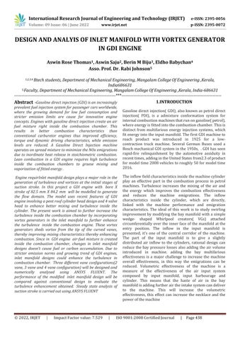
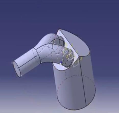
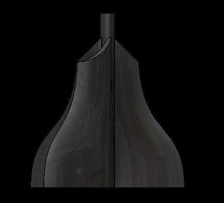
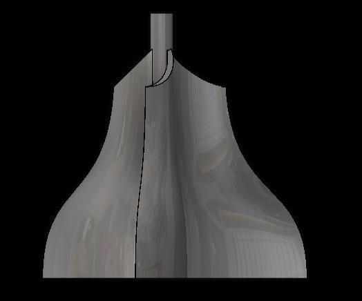
Geometry Modelling

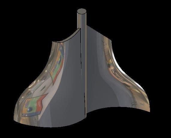
Here We are using CATIA software for designing the model. We have to study the region where the flow is occurring.

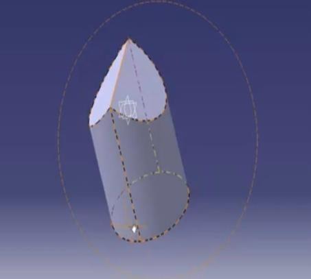
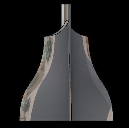
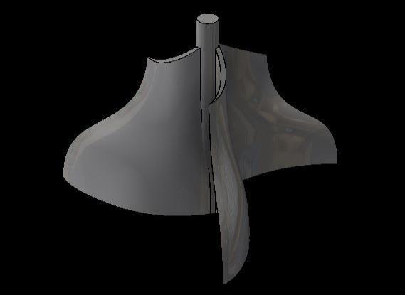
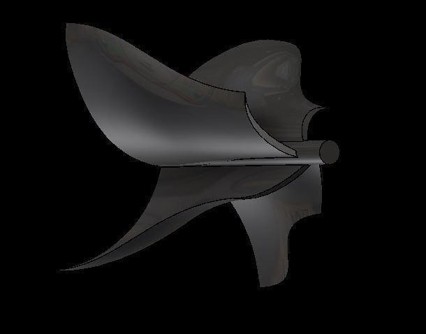
Design of vein
For designing the blade we are using autodesk inventor software.
e ISSN: 2395 0056
International Research Journal of Engineering and Technology (IRJET)
p
© 2022, IRJET | Impact Factor value: 7.529 | ISO 9001:2008 Certified Journal | Page441
Volume: 09 Issue: 06 | June 2022 www.irjet.net
ISSN: 2395 0072


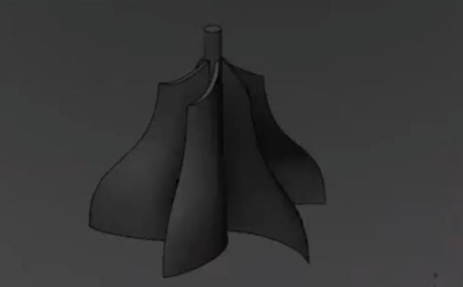
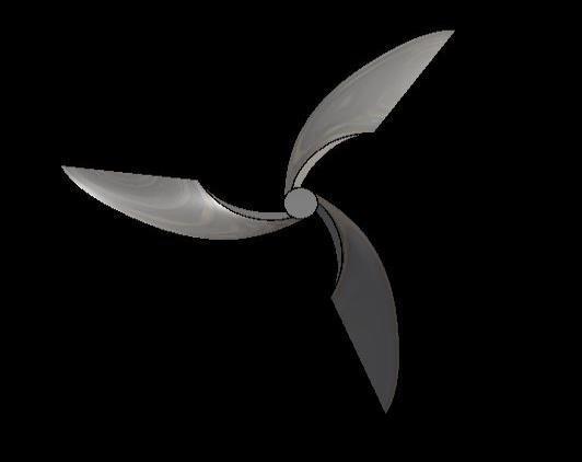
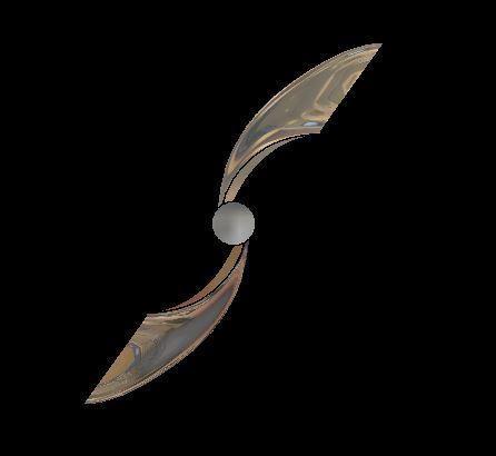
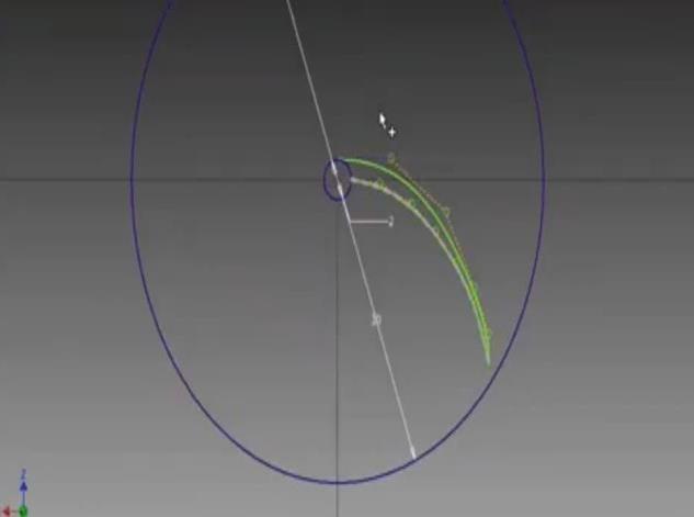
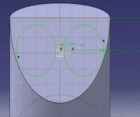
International Research Journal of Engineering and Technology (IRJET) e ISSN: 2395 0056 Volume: 09 Issue: 06 | June 2022 www.irjet.net p ISSN: 2395 0072 © 2022, IRJET | Impact Factor value: 7.529 | ISO 9001:2008 Certified Journal | Page442 Here3vanesareconnectedtotheshaftandplacedinthe inletmanifold 2 Vane Here 2 vanes are connected to the shaft and placed in the inletmanifold
3 vane
Isometric.view
Isometric.view
Top.view
Top.view
Governing Equations
The following governing equations are used for the analysis;
• Navier stokes equation
• Continuity equation.
Navier stokes equation
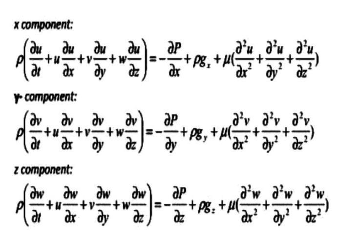
In the case when we consider an incompressible , isothermal Newtonian flow (density =const) viscosity µ =const),withavelocityfield V =(u(x,y,z), v(x,y,z), w (x,y,z)) wecansimplifythe Navier-Stokes equations tohisform:
Research Journal of Engineering and Technology (IRJET) e ISSN:
0056
09 Issue: 06 | June 2022 www.irjet.net p
© 2022, IRJET | Impact Factor value: 7.529 | ISO 9001:2008 Certified Journal | Page443
Isometric.view
International
2395
Volume:
ISSN: 2395 0072
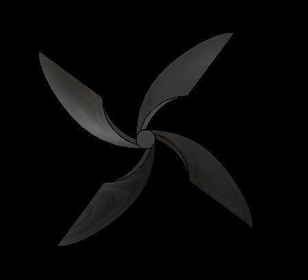
Top.view 4 vane Here 4 vanes are connected to the shaft and placed in the inletmanifold
International Research Journal of Engineering and Technology (IRJET) e ISSN: 2395 0056
Volume: 09 Issue: 06 | June 2022 www.irjet.net p ISSN: 2395 0072
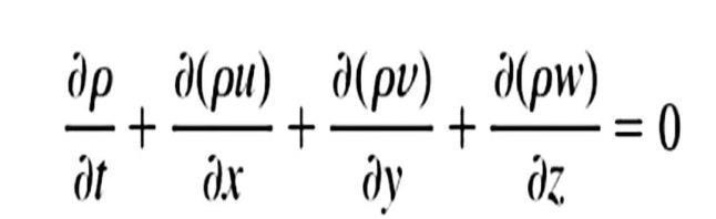
Continuityequation
Rateofchangeofmasswithinthecontrolvolumeisequal tothedifferenceofrateofchangeofmasswhichentersthe controlvolumeandtherateofchangeofmasswhichleaves thecontrolvolume
K Omega SST
The the model usedfor the simulationis K Omega model. Thek omega(k −ω)turbulence model isoneofthemost generally used models to capture the effect of turbulent inflow conditions. It belongs to the Reynolds equaled Navier Stokes( RANS) family of turbulence models where all the goods of turbulence are modeled. Then SST stands forShearStressTransportIt'satwo equationmodel.That means in addition to the conservation equations, it solves two transport equations ( PDEs), which regard for the history goods like convection and prolixity of turbulent energy. The two transported variables are turbulent kinetic energy( k), which determines the energy in turbulence, and specific turbulent dispersion rate( ω), whichdeterminestherateofdispersionperunitturbulent kinetic energy. ω is also appertained to as the scale of turbulence.
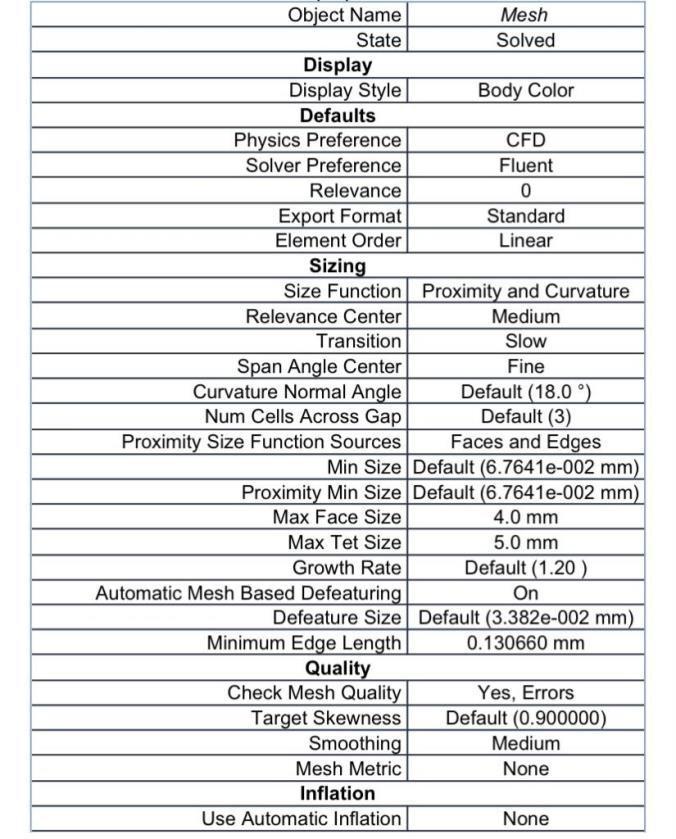
Meshing
The purpose of meshing is to actually make the problem solvable using finite element. By meshing the domain is breaked into subdomains ,each subdomains representing anelement.
Simulation
ForsimulationactivitiesweareusingANSYSsoftware.The requirementsoftheboundaryconditionswillbeasked accordingtotheNameinformationinmeshing.
*Cylinder=wall
*inletvelocity=11.26m/s
*temperature=300k
*outlet=wall *manifold=wall
. residualplot

© 2022, IRJET | Impact Factor value: 7.529 | ISO 9001:2008 Certified Journal | Page444
International Research Journal of Engineering and Technology (IRJET) e ISSN: 2395 0056
Volume: 09 Issue: 06 | June 2022 www.irjet.net p ISSN: 2395 0072
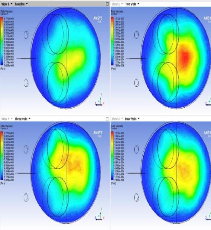
Contour of eddy viscosity
• Whiteline=continuityresidual
• Red =xvelocity
• Green =yvelocity
• Blue =zvelocity
Fromthisoutputresidualplotwecanunderstandthatthe simulationisstable.
Resultand Analysis
we use CFD Post for result and post processing. Here we compare the results of 2 vane ,3 vane and 4 vane against thebaseline
Initially we have constructed a plane near the TDC and analysisisdoneatthatplane,sinceairfuelmixingstartsat TDC.
Contour
Contouriscolourmapwhichareusedtofindchangein thepropertiessuchaspressure,kineticenergyetc accordingtocolurvariations.
Eddy viscosity
After selecting countor we select the variable as Eddy viscosity,and then select the number of contours as 100.and after loading we will get a result as shown in the figure.
Fromthefigureitisclearthateddyviscosityismaximum for2vane.Ifeddyviscosityishigh,itmeansthethereis highturbulence..
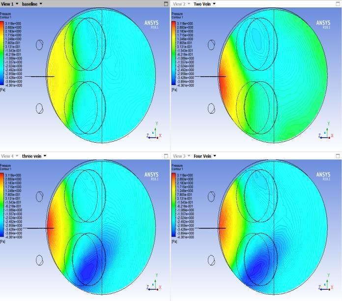
pressure
Nowweapplypressureasthevariable.Afterrunningwe willgetgetaresultasshowninthefigure.
Fromthefigureitisclearthatpressure ismaximumfor2 vanecomparedtobaseline,3vaneand4vane.
Streamline
Streamline shows the path of flow of air. We have select thestartingpointasinlet.Numberofpointsistakenas300 foreasyanalysing,andthevariableisselectedasvelocity.
The result is obtained as shown int the figure. Velocity streamline
Velocitystreamline
© 2022, IRJET | Impact Factor value: 7.529 | ISO 9001:2008 Certified Journal | Page445
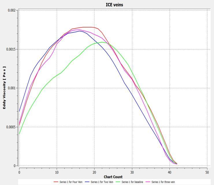
Graphresultofeddyviscosity
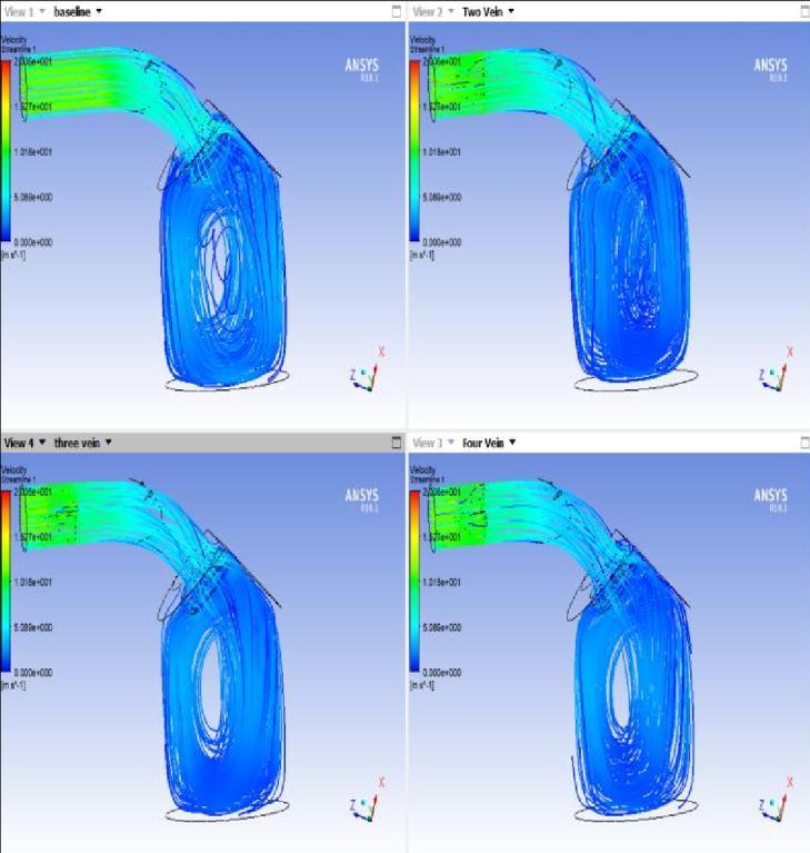
we can see that combined rotation in X,Y,Z axis is maximum for 2 vane compared to baseline ,3 vane and 4 vane.soturbulencewillbemorefor2vane.
GraphicalResult
Hereweconstructalineinlocation.thenwedefineinitial andfinalpoint.thenweselectthelocationasli9ne1.x axisrepresentvariationfromTDC BDC.
Yaxisrepresent variables.
Eddyviscosity
Afterselectinggraphicalresult,weselectthevariableas Eddyviscosity.andafterloadingwewillgetaresultas showninthefigure.
Fromthegraphitisclearthateddyviscosityismaximum for
2vane at the beginning compared to baseline, 3vane, 4vane.sowegetmoreturbulentcharacteristics.
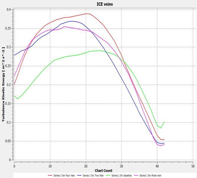
Turbulentkineticenergy
Afterselectinggraphicalresult,weselectthevariableas Turbulantkineticenergy.andafterloadingwewillgeta resultasshowninthefigure.
Graphresultofturbulentkineticenergy
From the graph it is clear that turbulent kinetic energy is maximum for 2vane at the beginning compared to baseline,3vane,4vane.so we get more turbulent characteristics.
International Research Journal of Engineering and Technology (IRJET) e ISSN: 2395 0056
09 Issue: 06 | June 2022 www.irjet.net p
0072 © 2022, IRJET | Impact Factor value: 7.529 | ISO 9001:2008 Certified Journal | Page446
Volume:
ISSN: 2395
International Research Journal of Engineering and Technology (IRJET) e ISSN: 2395 0056
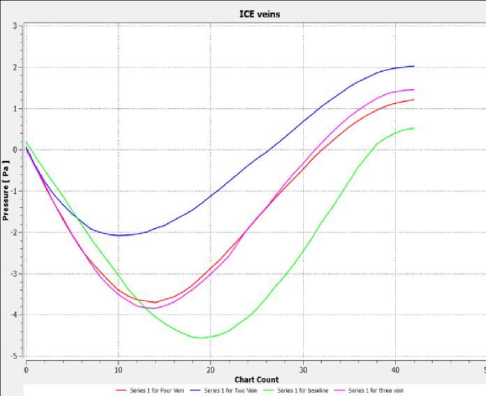
Pressure
Afterselectinggraphicalresult,weselectthevariableas Pressure,andafterloadingwewillgetaresultasshownin thefigure.
Lee J W, Kang K Y, Choi S H, Jeon C H, Chang Y J (2000) Flow characteristics and influence of swirl flow interactionsonsprayfordirectinjectiondiesel engine,In: Seoul 2000 FISITA world automotive congress, Seoul, 12 15June2000
Prasad BVVSU, Sharma CS, Anand TNC, Ravikrishna RV (2011) High swirl inducing piston bowls in small diesel engines for emission reduction, Appl Energy 88:2355 2367
Versteeg HK, Malalasekhara W (1995) An introduction to computational fluid dynamics: the finite methods. LongmanGroupLtd,London
Auriemma M., Caputo G., Corcione F.E., Valentino G. and RigantiG.2003.
Graphresultofpressure
Fromthegraphitisclearthatpressureismaximumfor 2vane comparedtobaseline,3vane,4vane.
Conclusion
So we can conclude that a 2vane can enhance the performanceofaGDIenginecomparedtothreevaneand4 vane.A 3vane is assymetric so vortex get interact each other ,which wont happen in case of 2 vane and 4 vane since they are symmetric. So there will be an increase in thetorqueofthevehicle.Wewillgetbetterairfuelmixing due to the turbulent flow air to the cylinder, due to which theamountoffuelwhichremainsunburntwillbeveryless andthepollutionisreduced.
Reference
VelteCM,HansenMOL,OkulovVL(2009)Helicalstructure of longitudinal vortices embedded in turbulent wall boundedflow.JFluidMech619:167 177
Paul B, Ganesan V (2010) Flow field development in a directinjectiondieselenginewithdifferentmanifolds.IntJ EngSciTechnol2(1):80 91 MartinsJ,Teixeira S,CoeneS (2009) Design of an inlet track of a small IC Engine for swirl enhancement, In: Proceedings of the 20th international congress of mechanical engineering, Gramado,15 20Nov2009 MuraliKrishnaB,Mallikarjuna JM(2009)Tumbleflowanalysisinanunfiredengineusing particle image velocimetry, In: Proceedings of world academyofscience,engineeringandtechnology,vol30
Volume: 09 Issue: 06 | June 2022 www.irjet.net p ISSN: 2395 0072 © 2022, IRJET | Impact Factor value: 7.529 | ISO 9001:2008 Certified Journal | Page447