International Research Journal of Engineering and Technology (IRJET) e ISSN:2395 0056

International Research Journal of Engineering and Technology (IRJET) e ISSN:2395 0056
Department Of Civil Engineering, Yeshwantrao Chavan College of Engineering (An Autonomous Institution Affiliated to Rashtrasant Tukdoji Maharaj Nagpur University), Nagpur, India. ***
ABSTRACT These days creation stakeholders don’t care how fancy a constructing information version (BIM) is, they care approximately having buildings accomplished on time with minimized overruns or errors. Traditionally, BIM has been used as a design tool to give structure, engineering, and construction (AEC) professionals a perception of the layout and creation of homes and infrastructure. This thesis has cited the integration of the extraordinary software. In this thesis it is easy to study the BIM procedure via the use of software like AutoCAD for 2nd Plans or Drafting, then Revit is used for the 3 d modeling, Microsoft project for Scheduling and planning then inside the ultimate Navis paintings for 4Dth measurement withthe3D versionSimulation.
KEYWORDS: AutoCad, Revit, Naviswork, Microsoft Project
What is BIM? Building data modeling is one of the most promising trends in the architecture, engineering, and production fields. It's miles converting the way contractors and engineers do business, however, its software continues to be relatively new and there is a great deal to examine. One manner to study is by watching how other agencies are the use constructing statistics. Modeling and their trials and tribulations alongside the manner. Constructing records Modelling changed added over a decade ago especially to differentiate the records wealthy architectural three D modelingfromthetraditionalseconddrawing.It'smiles being acclaimed by using its advocates as a lifesaver for complex initiatives because of its capacity to accurate errors early within the layout degree and correctly agendaconstruction.
AutoCAD is an industrial software (CAD) and drafting software application. Advanced and advertised through Autodesk. AutoCAD was first launched in December
1982 as a computer app strolling on microcomputers with internal graphics controllers. Before AutoCAD becomes delivered most commercial CAD applications ran on mainframe computers or minicomputers, with every CAD operator (person) engaging at a separate pix terminal. AutoCAD is likewise to be had as mobile and net apps. AutoCAD is used in industry, employing architects, challenge managers, engineers, photograph designers, town planners, and other specialists. It had been supported by way of 750 training centers worldwidein1994
2.1.1
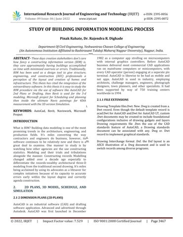
i. DrawingTemplatefiles.Dwt:New.Dwgiscreatedfroma. Dwt record. Even though the default template record is acad.Dwt for AutoCAD and.Dwt for AutoCAD LT, custom .Dwt documents may be created to include foundational configurations inclusive of drawing gadgets and layers
Drawing requirements file .Dws the use of the CAD standards feature of AutoCAD, a Drawing standards document can be associated with any. Dwg or. Dwt recordtoimplementgraphicalstandards. ii.
iii.
Volume: 09 Issue: 06 | June 2022 www.irjet.net p ISSN:2395 0072 © 2022, IRJET | Impact Factor value: 7.529 | ISO 9001:2008 Certified Journal | Page3467
Drawing Interchange format .Dxf. the Dxf layout is an ASCII illustration of a. Dwg document and is used to switchrecordsamongdiverseprograms.
International Research Journal of Engineering and Technology (IRJET) e ISSN:2395 0056
Volume: 09 Issue: 06 | June 2022 www.irjet.net p ISSN:2395 0072
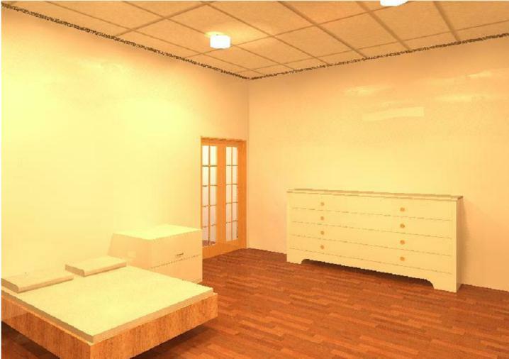
purpose of sharing it in a common statistics surroundings (CDE). BIM 3 D fashions are employed for schematic designs, layout development and documentation, creation documentation, and record drawings. Via the usage of three D BIM, you may be capable of keeping your employees up to date on the modern daylayouttraits
2.2.1
RTE (template) files and RVT (task) documents are real Revit projects. The distinction between the two is that the template is used to start a new undertaking. When you click on the store, you will now not be allowed to overwrite the template file, however, you'll be precipitatedforabrandnewreportnameandarea.RFA (family) documents and RFT (own family template) documents are own family files that could either be loadedright into a venture orsaved externally.Circle of relative template documents is used to begin a brand new circle of relatives from scratch and own family documents are typically used to alternate households amongprojects
Revitsupportsawiderangeofindustrystandardsand fileformats,including:
i. Revitnativeformats:RVT,RFA,RTE,RFT.
ii. CADformats:DGN,DWF,DWG,DXF,IFC,SAT,and SKP
iii. Imageformats:BMP,PNG,JPG,JPEG,andTIF.
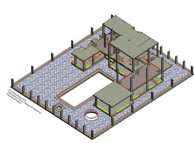
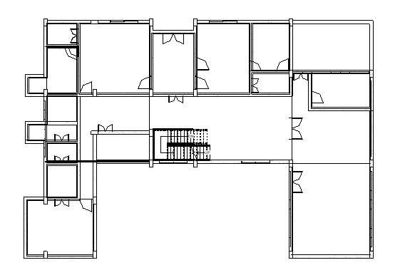
3 D represents the 3 dimensional geographical systems ofabuilding thisistheX axis,theY axis,andtheZ axis of a building. Three D BIM entails the creation of graphical and non graphical building data for the sole
iv. Otherformats:ODBC,HTML,TXT,andgbXML Fig.no.33DFrameStructure
International Research Journal of Engineering and Technology (IRJET) e ISSN:2395 0056 Volume: 09 Issue: 06 | June 2022 www.irjet.net p ISSN:2395 0072
how the project will evolve over the years. This visualization of this data is extraordinarily beneficial in early stage conflict detection. Using a 4D version will help improve website planning and scheduling optimization.It'sgoingtoalsoincreasethepreparedness of stakeholders by way of better speaking the subsequent steps at some point of each stage of production
MPP is the extension associated with the Microsoft projectfactsfile,developedthroughMicrosoftemployer. Microsoft'smissionisthe challengecontrol softwarefor organizing, monitoring, and preserving project plans, utilized by challenge managers, stakeholders, and those insidethechallengecrew.Itismilesdesignedforhuman beings, teams, and agencies of all sizes to offer assignment control assets and tools, in addition to related systems for collaboration. Microsoft mission is often used alongside Microsoft project Server to unify mission management by imparting web based collaboration equipment for reporting, enterprise instances,andprolongedinteroperability Fig.no.7.SchedulePlan
3.4.
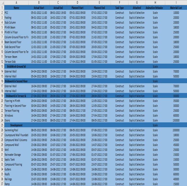
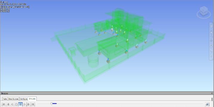
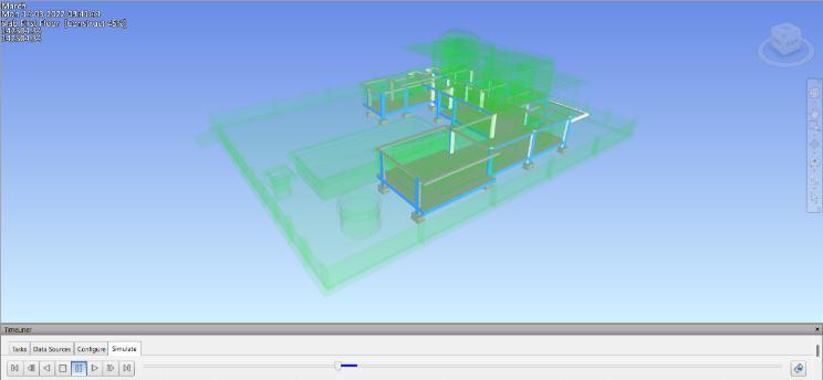
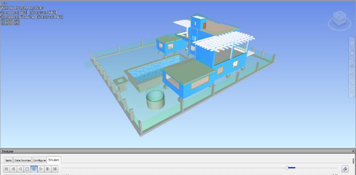
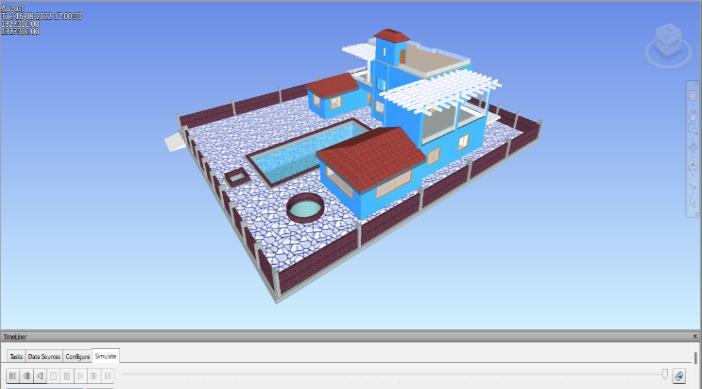
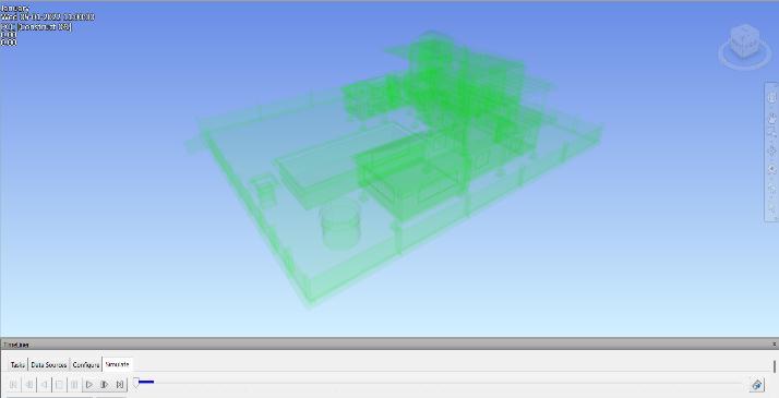
The 4th dimension in a BIM model shows the period of an undertaking. The inclusion of a timeline and scheduling statistics in the BIM version helps display
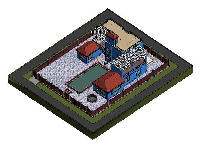
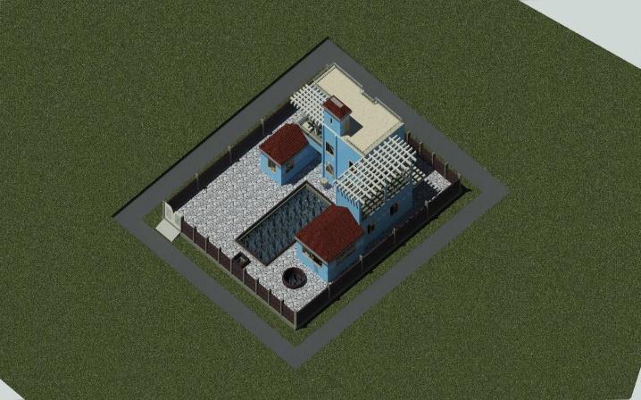
Autodesk Navisworks control is pleasantly described as a version aggregator that is designed to convey collectively 3 d fashions and their related design informationintoasinglerunningsurroundingforlayout assessment, coordination evaluation, simulation, and presentation.
To study the Building Information Modeling process (BIM). I studied the different stages of the BIM process andlearnedaboutthesoftwareinvolvedinthisprocess.
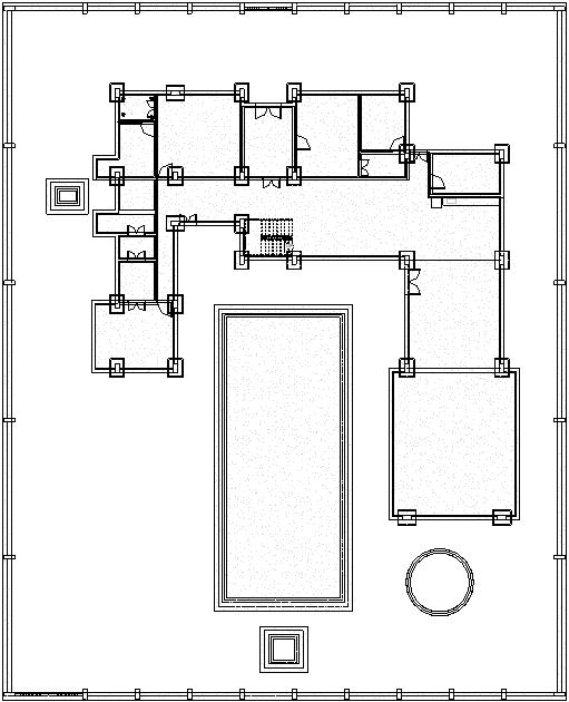
In this study paintings. I made a hypothetical 2d plan in AutoCAD2dandtakingthatplanasareferenceImadea 3 D model inside the software called Revit structure. ThenIScheduledeveryactivitywiththeaidofgivingthe pastime a begin date and cease Date in Microsoft assignment, the software program used for Scheduling. After that, I exported the Revit model into the software program Naviswork control for a 3 d simulation of the designed three D version. Additionally inserted the agendaplanintothissoftware
The result of this venture is that it made the entire productionprocedurequitelessdifficult.BIM isawhole technique that every mission stakeholders take whilst planning,building,anddealingwitha newtask.The use ofBIMgivesacoupleofblessingstoeverybodyinvolved inthetask.And,ultimately,itresultsinbettereffect
Using BIM and BIM conscious gear which include those defined in the challenge can provide you with early information on what the scale, website online, and constructingsituationsareandwhatthecostofaproject is. The use of BIM, and the technology that assist its various makes to uses, help tell the mission crew and streamline approaches. You could use web page evaluation equipment to recognize multiple websites and speak capability advantages and disadvantages of
International Research Journal of Engineering and Technology (IRJET) e ISSN:2395 0056
Volume: 09 Issue: 06 | June 2022 www.irjet.net p ISSN:2395 0072
each without leaving your table. As a layout version modifications at some stage in the route of an undertaking, you may use the BIM as a device to coordinate takeoff and fees. The use of this indicates of estimating creates a proactive design to budget technique with the architect and engineering team, instead of handling a reactive response to fee engineeringsituationslater.TheusageofBIMentailsthe usageof both evaluation toolsandmodeling equipment, and each is important to a systemic BIM process. Expertise that there may be a distinction between the 2 tools will clarify destiny responsibilities and applications. This e book indicates which equipment (and identifies similar tools) are relevant to each challenge, a method for how it can be achieved, and the abilitytoquantifythetimeandeffortittakestoperform thosetasksfordestinyreference.
[1] Bilal Succar “Building Information Modelling: conceptual constructs and performance improvement tools”UniversityofNewcastleDecember2013.
[2] Willy Sher, Anthony Williams “An integrated approach to BIM competency assessment, acquisition andapplication”UniversityofNewcastle20June2013
[3] Guillermo Aranda Mena, Tony Williams “A proposedframeworktoinvestigatebuildinginformation modeling through knowledge elicitation and visual models”,RMIT,UniversityofNewcastle,October2013
[4] Barazzetti, F. Banfi, R. Brumana, G. Gusmeroli, D. Oreni, M. Previtali, F. Roncoroni, G. Schiantarelli “Bim fromlasercloudsandfiniteelementanalysis:combining structural analysis and geometriccomplexity”European SchoolOfArchitecture February2015.
[5] Mohamad Kassem, “Macro BIM adoption Conceptualstructures”CentreforInterdisciplinaryBuilt EnvironmentResearch(CIBER),UniversityofNewcastle, Australia Technology Futures Institute, Teesside University,UnitedKingdom April2015.
[6] Sherif M. Ahmed, Hassan H. Emam, and Peter Farrall,“UseofGanttChartsforSchedulingandPlanning” June2015
[7] Nassar, Reema, and AL Qasem, Imad. “Cost estimation is a key part for any project planning” September2020.
[8] Dr. Keith D. Hampson, Dr. Judy A. Kraatz, Adriana X. Sanchez, MSc “Integrated Project Environments:BriefingReportforIndustry” Sustainable BuiltEnvironmentNationalResearchCentre,July2014
[9] C.Achille,N.Lombardini,andC.Tommasi,“BIM and cultural heritage: compatibility tests in an archaeological site” 3D Survey Group, ABC Department, PolitecnicodiMilano,ItalyJuly2015
[10] Steve Rollinson, Martin Tuuli, Ronan Collins, “Relationship Management with the help of BIM” Loughborough University Institutional Repository, June 2009