International Research Journal of Engineering and Technology (IRJET) e ISSN: 2395 0056

Volume: 09 Issue: 06 | Jun 2022 www.irjet.net p ISSN: 2395 0072
International Research Journal of Engineering and Technology (IRJET) e ISSN: 2395 0056
Volume: 09 Issue: 06 | Jun 2022 www.irjet.net p ISSN: 2395 0072
2
1PG student, Dept. of Civil Engineering, KMEA Engineering college, Kerala, India
2Asst.Proffessor, Dept. of Civil Engineering, KMEA Engineering college, Kerala, India ***
Abstract - Steel I girders have been widely used in building and bridge engineering due to its ease of construction and high flexural strength. During the erection of beams or decks over the flanges of steel bridge girder it will exerts a load on the flange as concentrated load. This is also occurred during bridge launching generally termed as patch loading. Under patch loading the web starts buckling which will in turn causes serious structural damages.so this research aims at enhancing the resistance to patch loading which causes web buckling. In the present study the structural optimisation of flat and corrugated I girder is considered. The strengthening against patch loading is done by means of modifications in flange as well as web part of the girder. Hollow flange, concrete filled flange and web stiffeners are used here to resisting the web buckling caused by patch load. A non linear static analysis is conducted on the models created in the finite element software ANSYS workbench
Key Words: Corrugated girder (CG), Flat girder (FG) Patch loading, Concrete filled flange and hollow flange, Nonlinear static analysis
Steelbridgesareextensivelyutilisedworldwideinavariety of structural shapes and span lengths, including for footbridges,railroadbridges,andhighwaybridges.Strength, ductility,easeofproduction,andquickconstructionarethe keybenefitsofstructuralsteeloverotherbuildingmaterials. When beams or decks are built over the flanges of a steel bridgegirder,aconcentratedloadisappliedtotheflange. This also happens when a bridge is launched, a process known as patch loading. A load instance where a concentrated force is applied perpendicular to a girder's flangeisknownaspatchloadingorpartialedgeloadingof steel girder webs. The girder web typically fails locally aroundtheloadedflangeasaresultofthis.
Underpatchloading,the webbeginsto buckle,which will lead to significant structural damage. Web buckling is the failureofthewebcausedbyafocusedload.Whentheweb buckles,columnactionisappliedtoit.Whenthewebistoo thintosupportthetransverseforcebeingtransmittedfrom theflange,bucklingofthewebresults.SteelIgirdershavea threat from the web buckling under patch stress, which compromisestheirstabilityandlongevity.Consequently,a numberofadjustmentsaremadetoimprovetheirstructural
resistance to patch stress. Among these, utilizing web stiffenerswasoneofthebestmethods.Webstiffenersused in structural modification to lessen patch loading are commonly recognized. However, flange alteration is quite uncommon.Ifachangeismadetotheflanges,whicharethe major components under the focused load, it will offer relativelygoodresistancetothatload.Intermsofstructure, hollow and concrete filled flanges predominate over standardflanges.
TodocomparativeresearchCorrugatedandflatIgirdersare the two types of I girders employed in this investigation. Webstiffenersareusedaspartofstructuralalteration,and hollow and concrete filled flanges are included in flange modification.The
concrete filled tubular flange in the new I girder has substantially better torsional and flexural rigidity, which helps to increase resistance to global buckling. Because corrugated web has significantly stronger out of plane bending stiffness and shear stiffness than flat web with transverseorlongitudinalstiffeners,whichismuchlighterin weightduetoitsextremelytinythickness,itcanincreasethe web'scapacitytowithstandlocalbucklingmoreeffectively [1]. The concrete filled flange is discovered to give higher buckling resistance. This emphasizes the impact of the concreteinfill,whichmakestheupperflangemorerigidand enablesthemembertosupporthigherforces[2].
• To investigate the performance of flat and corrugated girder with hollow flange under differentparametricpatchloadingcondition
• Tostudytheimprovementofpatchloadresistance bymodifyingtheflangewithconcretefilledflange andwebbymeansofwebstiffeners
• To compare the performance of girder after structuraloptimization
Themainobjectiveofthestudyistoincreasewebbuckling resistancetopatchloading.Forthat,corrugatedandflatweb patternedIgirdersareemployed.andforbothIgirders,the flange piece is built from a hollow section. these models
International Research Journal of Engineering and Technology (IRJET) e ISSN: 2395 0056
experience various durations of patch loading (100 mm,150mm,200mm,250mm).Thelengthofthepatchload that results in the greatest buckling value ischosen as the ideal patch load length and is employed in subsequent research.thentheflatandcorrugatedmodelsareintroduced forstructuraloptimizationforbothflangeandweb.Theweb modification uses both vertical and horizontal stiffeners, whiletheflangemodificationusesaconcretefilledflange.A nonlinearstaticanalysisisperformedfortheallmodelsin ANSYSWORKBENCHsoftware
ANSYSWORKBENCHsoftwareisusedtocarryouttheentire analysis. The investigation's model specifications call for both types of I girders to have 1500 mm length, 225 mm flange width, 20 mm flange thickness, and 500 mm web heightand6mmwebthickness[3].TheTable1belowlists themodel'sattributes.
Youngsmodulus (Gpa) 210
Poisonsratio 0.3
Yieldstressofweb(Mpa) 379
Ultimatestressofweb(Mpa) 517 Yieldstressofflange(Mpa) 373
Ultimatestressofflange(Mpa) 542
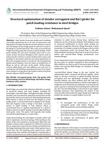
Figure 1 depicts the corrugated profile used to create corrugatedgirder.Thecorrugationprofileisthesameforall specimens.Hollowsectionsareof225mm×75mm×10mm.
patching load lengths and four similar hollow flanged corrugatedgirderswithvaryingpatchloadinglengthswere evaluated as part of the research. Consequently, eight of thesemodelsweredevelopedunderthetitlesFG P100,FG P150,FG P200,CG P100,CG P150,CG P200,andCG P250.
Thegirdersareonlysupported,withpatchloadsofvarying lengths given to the top of the flange. The hexahedron shapedmeshingelementshaveanelementsizeofabout25 mm and adaptive mesh control. To investigate the functionality of an I girder with hollow flanges, nonlinear staticanalysisisused.Westudydeformation,webbuckling, andloadbearingability.
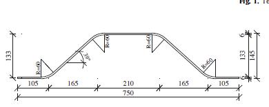
Afterperforminganon linearstaticanalysis,itwaspossible to determine the maximum load bearing capacity and ultimatedeflectionforflatandcorrugatedgirderwithhollow flange.Thedataareshowninatable2alongwiththeweb's maximumloadandbucklingcapacity.
The web buckling curve for flat girder (FG) shows that substantial buckling occurs whether the hollow portion is employedornotshowninChart.2.Additionally,thegraph makesitevidentthatthelongestpatchloadingtimesresult in the greatest amount of buckling. In contrast, low web bucklingvaluesforcorrugatedgirderswithhollowflanges are seen for various patch loadings in Chart. 3. In cases where patch loading is higher, the load bearing ability is larger.
Todeterminetheimprovedperformance,thewebbuckling andloaddeflectioncurvesforbothFGandCGwithhollow flangearecomparedinchart.4.Thewebbucklingisgreatly reducedwhenhollowflangesareusedincorrugatedgirders, accordingtoastudyofwebbucklingandultimateloadfor FGandCG.Additionally,itisclearthatFGhasalowerload bearingcapabilitythanCG.
Table 2 Deflectionmaximumloadvalueofdifferent
Allofthemodelswereproducedas3Dmodelsforanalysis. Four models of hollow flanged flat girders with varying
Volume: 09 Issue: 06 | Jun 2022 www.irjet.net p ISSN: 2395 0072 © 2022, IRJET | Impact Factor value: 7.529 | ISO 9001:2008 Certified Journal |
International Research Journal of Engineering and Technology (IRJET) e ISSN: 2395 0056
Volume: 09 Issue: 06 | Jun 2022 www.irjet.net p ISSN: 2395 0072
Chart 2: WebdeflectioncurveforFG
Thestudiesmentionedabovedemonstratethatforagiven increaseinpatchload,flatgirderandcorrugatedgirderload bearing capacities improve by up to 7% and 10%, respectively.Thepercentagesofaxialdistortionforflatand corrugated girder are 10 and 6 percent, respectively. Accordingly,flatgirderwithhollowflangeperformsworse overall than corrugated girder with hollow flange. Accordingly,flatgirderwithhollowflangeperformsworse overallthancorrugatedgirderwithhollowflange.
Accordingly,flatgirderwithhollowflangeperformsworse overallthancorrugatedgirderwithhollowflange.
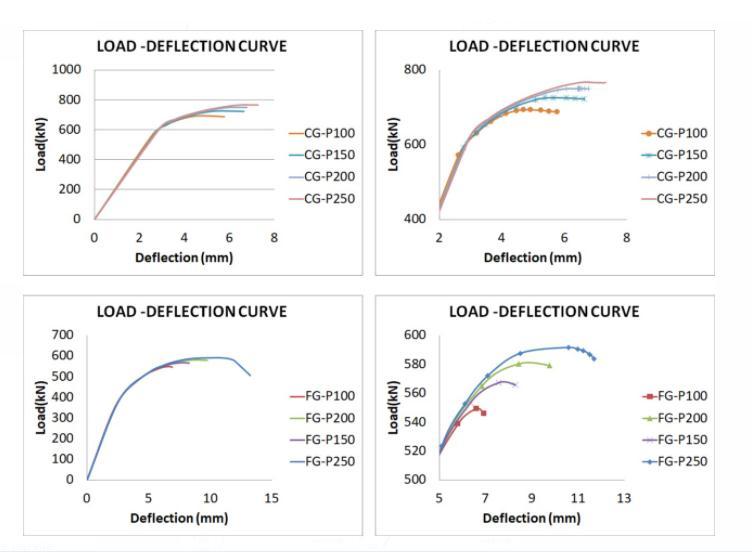
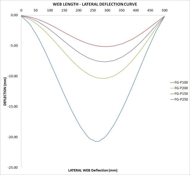
Chart-4: Comparisonforloaddeflectioncurve
5. ANALYSIS OF FLAT and CORRUGATED I GIRDER WITH FLANGE AND WEB STRENGTHENING UNDER 250 mm PATCH LOAD
Accordingtoearlierresearch,apatchloadingwitha250mm length delivers the greatest load bearing ability. Analysis with a 250 mm patch load is a better alternative for the upcoming research than choosing other patch loading lengths. It is examined in this section how alternative structural modifications to flat and corrugated I girders under 250 mm patch loading compare. The flange modification involves r filling the flange with M25 grade concrete. table 3's description of the concrete's qualities. reinforcing the web by adding web stiffeners in both the horizontalandverticaldirections
Table 3: CharacteristicsofM25Concrete M25 Tensile strength Compressive strength Poisons ratio 3.2 25 0.2
Chart-3: WebdeflectioncurveforCG
Section4haspreviouslymadereferencetothespecification and characteristics of both I girders. Consequently, six models were created, three for flat girders with concrete filledflangesandhorizontalandverticalstiffenersandthree forcorrugatedgirdersinasimilarfashion.CF FG 250,H FG 250,V FG 250,ANDCF CG 250,V CG 250,H CG 250arethe names of the models. Here, 50 mm wide by 5 mm thick verticalandhorizontalstiffenersareemployed.Thevertical stiffenersare10 0millimetresapart
International Research Journal of Engineering and Technology (IRJET) e ISSN: 2395 0056
Volume: 09 Issue: 06 | Jun 2022 www.irjet.net p ISSN: 2395 0072
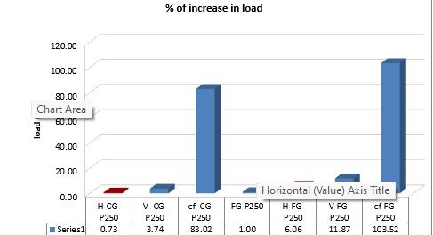
Afteranalysis,thecorrugatedgirderwiththeconcrete filled flange exhibits the most web buckling, whereas the corrugatedgirderwithverticalstiffenersasshowninChart5 and Chart. 6 exhibits the smallest. However, the concrete filled modification employed in the flange exhibits good corelationintermsofloadbearingability.ForbothFGand CG, the load capacity improves by more than 83 percent (Chart 7)
Overall,stiffenersdonotofferasmuchloadcapacityasthe concretefilledflangemodification.
We had determined in the last section that corrugated girdershavelesswebbucklingthanthecompetition.Thus,it is once more demonstrated that the corrugated girder model's modification decreases web buckling more effectivelythanflatgirderwhichisshownChart.9.Theuse ofstiffenersincorrugatedgirderisthegreatestalternative fordecreasingbucklingcausedbypatchloadamongthose adjustments,asisevidentfromChart.7.
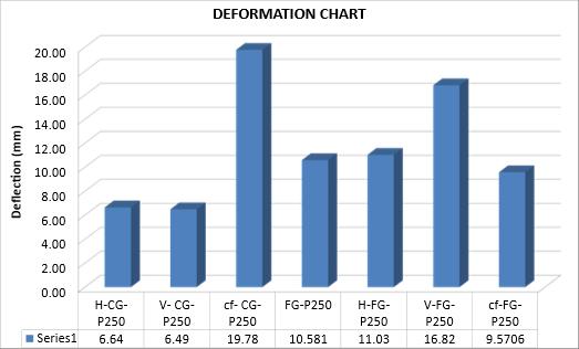
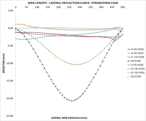
Chart 5:Flatgirderloaddeflectioncurve
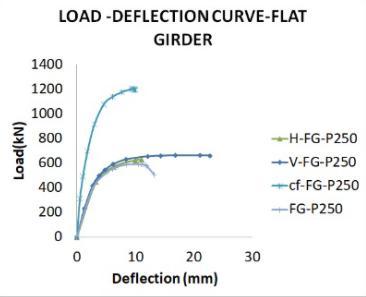
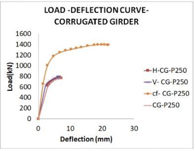
Chart-6:Corrugated girderloaddeflectioncurve
Chart 9:DeflectionInModifiedModels
Chart 8:Webdeflectioncurveforstrengthendmodels
International Research Journal of Engineering and Technology (IRJET) e ISSN: 2395 0056
Volume: 09 Issue: 06 | Jun 2022 www.irjet.net p ISSN: 2395 0072
ThisstudyexaminedtheresistanceofseveralI girdertypes to patch loading, which results in web buckling, and the structural optimization thereof. In order to analyse the developed3DmodelsoftheflatandcorrugatedIgirders,a nonlinearstaticanalysiswasconducted.Differentloadings oftheparametricpatchareusedtotestthemodels.Theideal patch loading length is determined and then utilised for girderstructuraloptimization.Thefindingswereasfollows:
Accordingtotheanalysis'sfindings,corrugatedand flat I girders both suffer less web buckling when hollow flanges are used. Flat girder with hollow flange’s load carrying capacity for the increase in patchloadincreasesbyupto7%,whilecorrugated girder withhollow flange'sloadcarryingcapacity improvesbyupto10%.
Themaximumvalueforbothloadbearingcapacity and deflection is provided by a set patch loading lengthof250mm..
The structurally modified flat and corrugated I girder provides superior results for web buckling and load bearing capability under a patch load of 250mm.
Whenitcomestoloadbearingcapacity,structural optimization employing a concrete filled flange showsstrongcorrelation.Increasedthan83percent moreloadcapacityisgainedforbothFGandCG.
Usingstiffenersincorrugatedgirderisthebest solutionforreducingbucklingbroughtonby patchloadintheweb.
From a comprehensive review of the literature, it can be inferred that structural optimization in steel bridges increasesresistancetowebbucklingbroughtonbythepatch load.
[1] YongboShaoandYaminWang,“ExperimentalStudyon static behavior of I girder with concrete filled rectangular flange and corrugated web under concentratedloadatmidspan,”engineeringstructure, vol.130,Jan.2017,pp.124 141,
[2] AlDujelaandKA Cashell,“Flexuralbehaviorofconcrete filled flange girder,” Journal of constructional steel research,vol.151,Dec.2018,pp.263 279,
[3] BkovesdiandL.Dunai,“Determinationofpatchloading resistance of girder with corrugated web using Nonlinear finite element analysis,” Computers and Structures,vol.89,Nov.2011,pp.2010 2019,
2022, IRJET | Impact Factor value: 7.529 | ISO 9001:2008 Certified Journal