International Research Journal of Engineering and Technology (IRJET) e ISSN: 2395 0056

International Research Journal of Engineering and Technology (IRJET) e ISSN: 2395 0056
1Post Graduate Student, Computer Aided Structural Engineering, Ilahia College of Engg & Tech, Kerala, India 2 Asst Professor, Dept of Civil Engg, Ilahia College of Engg & Tech, Kerala, India ***
Abstract Precast concrete construction is widely used in many countries for its manyadvantages.Butitsconstructionis limited in high seismic zones because it depends on the behavior of connections of a precast structural system. Beam column joints were considered as the critical zone of reinforced concrete moment resisting structure subjected to seismic loads. Seismic retrofitting is the modification of structures to make them more resistant to seismic activity. There are many methods of retrofittingadoptedforcastinsitu beam column joint. A lot of studies are ongoing on the effectiveness of these retrofitting methods in the cast in situ beam column joints This report is ananalyticalinvestigation carried out for strengthening of precast beam column joint subjected to monotonic loading using steel plates and angles. Strengthening is carried out in two different methods. One of the methods is the welding of steel plates and angles to the beam column joint and another method is steel plates and angles are mounted by using prestressed bars Results obtained from the analyticalstudyarethencomparedwith the experimental results of the cast in situ beam column joint subjected to monotonic loading. Strengthening of precast beam column joint aims to improve structural performance like joint strength, ductility, ultimate moment capacity, and ultimate deflection. This study also aims to ensure the effectiveness of these strengthening techniques in the cast in situ beam column joints since it makes better results in the structural performance in precast beam column joints
Key Words: Precast, Cast in situ, Strengthening, Seismic, Joint, Beam, Column
Mostofthereinforcedconcretestructuresbefore the 1970s were not designed based on the current seismicguidelines.Thestudiesshowedthatthefailure ofstructuresbytheearthquakeisduetothefailureof the exterior beam column joint. This was due to inadequate joint transverse reinforcement and poor anchorage length of beam longitudinal bars. Seismic retrofittingisadoptedtostrengthentheseweakened beam column joints. Concrete jacketing, steel jacketing,CFRP,bracingandbuttressaresomeofthe usually adopted strengthening methods. But these
methods have advantages and also some disadvantages.Castinsitubeam columnjointsusing steelplatesandanglesshowedstrengthimprovement. Likecast in situconstruction,precastconstructionis also gaining more importance nowadays for its benefits. Reduced requirement of formwork and scaffoldings, less time consumption, and reduced amountofwastematerialsatthesitearesomeoftheir benefits.Butitsapplicationislimitedinhighseismic zones because of scarce design guidelines compared withthoseofcast in placeconcretestructures.Inhigh seismic zones, they depend on the behavior of connectionsbecausetheyconstitutetheweakestlinkin thestructure.Theobservationsfrompastearthquakes showthatalotofresearchhastobedonetoadoptthe precast systems in high seismic zones. This paper presentstheanalyticalinvestigationofthecastinsitu beam column joints and precast beam column joint subjected to monotonic loading. The analytical investigationiscarriedoutinsoftwarecalledANSYS.It isageneral purpose,finite elementmodelingpackage for numerically solving a wide variety of mechanical problems. These problems include static/dynamic, structuralanalysis,heattransfer,andfluidproblems,as well as acoustic and electromagnetic problems. It helpsincivil,automotive,aerospace,andwhereverone needstodesignsomething,andvalidatethatdesignfor therealworld,inexpensively
Mohie E Shoukry et al. (2021)[1] Studiedthe SeismicretrofitofdeficientexteriorRCbeam column joint using steel plates and angles. In this journal RC beamcolumnjointisfittedwithsteelplatesandangles around the joint with different configurations like X shape, horizontal, etc. six half scale exterior beam column joints including two control specimens representing code detailed and deficient joint in additiontofourretrofittedspecimensweretested. The resultshowedthatdeficientjointexhibitedbrittlejoint shearfailure,codedetailedjointfailedbyflexureinthe beam,andretrofittedspecimenspreventedbrittlejoint
Volume: 09 Issue: 06 | Jun 2022 www.irjet.net p ISSN: 2395 0072 © 2022, IRJET | Impact Factor value: 7.529 | ISO 9001:2008 Certified Journal | Page3391
International Research Journal of Engineering and Technology (IRJET) e ISSN: 2395 0056
shear failure and increased joint strength, ductility, stiffness,andenergydissipation.
Jansi Rani K et al. (2019)[2] Studied the experimental investigation on seismic retrofitting of RCC structures. This journal is an experimental investigationonseismicretrofittingofRCCstructure.A typical beam column joint with detailing as per code scaledowntolaboratoryconditionsandsubjectedto reverse cyclic loading was examined for lateral load capacity.Thespecimenswereclassifiedintotwotypes such as a non ductile joint represented as a control specimen and a conventionally retrofitted specimen using concrete jacketing. The retrofitted specimen showedappreciableseismicbehaviorthrough plastic hingeformationinthebeam.
Jalil Shafaei et al. (2014)[3] studiedtheSeismic retrofit of external RC beam column joints by joint enlargement using prestressed steel angles. In this journal seven half scale external RC beam column jointsweretestedbyapplyinglateralcyclicloadingof increasingamplitudes.Thetestedspecimenscomprised three control units and four retrofitted units. Parameters on seismic behavior were determined, including strength, stiffness, ductility, energy dissipation capacity, equivalent hysteresis damping, andrelativeenergydissipationratio.Theresultswere compared to those of the control specimens. The proposedretrofitmethodresultedintherelocationof the plastic hinge away from the column face to the outsideofthejointpanelzone.
Mohamed H. Mahmoud et al.(2014) [4] studied thestrengtheningofdefectedbeamcolumnjointusing CFRP.Thisjournaldealswiththeexperimentalstudyof the structural performance of reinforced concrete exteriorbeam columnjointsrehabilitatedusingcarbon fibrereinforcedpolymerCFRP.Anexperimentalstudy was conducted on ten half scale specimens covering three possible defects in addition to an adequately detailed specimen. Three different strengthening schemeswereusedtorehabilitatethedefectedbeam columnjointsincludingexternallybondedCFRPstrips andsheetsinadditiontonear surfacemounted(NSM) CFRP strips. The test result showed that CFRP strengthening configuration represented the best choice for strengthening from the viewpoint of the studiedfailurecriteria.
R. Vidjeapriya and K. P. Jaya (2013) [5] studied an experimental study on two simple mechanical precastbeam columnconnectionsunderreversecyclic loading.Inthisjournalprecastspecimenandmonolithic specimenaredesignedforthesamestrength.Thefirst precastconnectionthebeamisconnectedtothecorbel using a cleat angle with a single stiffener andfor the
second precast connection cleat angle with two stiffeners was used. The sub assemblage specimens havebeensubjectedtocyclicdisplacementcontrolled lateralloading.Themaximumloadcarryingcapacityof the monolithic specimen was higher than precast connection and energy dissipation and ductility was higher for monolithic specimen compared to the precastspecimen.
Studies on past earthquakes such as the 1994 Northridgeearthquake Mitchel et al.[6] Andthe1998 Adana Ceyhan,Turkeyearthquake Gulkan[7] showed extensive damage to precast structures due to the failure of connections. They also observed that even though these precast structures behaved ductile manner, the lack of proper diaphragm action and inadequateconnectionsbetweenbeamsandcolumns contributedtothecollapse.
Table 1: Dimensionsofbeamcolumnjoint Parameter Beam (mm) Column(m m)
Crosssection 200X300 200X300 Length 900 2300
Table-2: Materialpropertiesofbeamcolumnjoint Material Concrete steel Properti es Compressiv estrength Longitudin al reinforcem entyield strength
Stirr ups yield stren gth
Modul usof elastic ity
Value 25Mpa 400Mpa 240 Mpa 200 Gpa
The beam column joint is modeled in the ANSYS software. Element type SOLID 185 and REINF 264 is used for the 3 D modeling of concrete and reinforcement.Dimensionsandmaterialpropertiesare brieflydescribedinTable1andTable2 Themainsteel reinforcement of the beam was three bars of 16 mm diameterandsecondarysteelreinforcementwastwo bars of 12 mm diameter. The column was reinforced withfourbarsof16mmdiameterateachcornerofthe columncross section.Thestirrupsforbothbeamand columnweresteelbarsof8mmdiameterandspaced every100mmand150mmforthebeamandcolumn.In
Volume: 09 Issue: 06 | Jun 2022 www.irjet.net p ISSN: 2395 0072 © 2022, IRJET | Impact Factor value: 7.529 | ISO 9001:2008 Certified Journal | Page3392
International Research Journal of Engineering and Technology (IRJET) e ISSN: 2395 0056
Volume: 09 Issue: 06 | Jun 2022 www.irjet.net p ISSN: 2395 0072
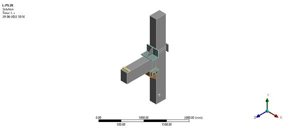
additionthreestirrupswereaddedatthebeam column joint. Including a monolithic beam column joint, a precastbeam columnjointwithoutstrengthening,five models of strengthened precast beam column joint withweldedsteelplatesandangles,andsixmodelsof strengthened precast beam column joint with prestressed bars; a total of 13 models are prepared. After modeling the monolithic beam column joint, precast beam column joint is developed using cleat angle with single stiffener, and corbel is used for supportingbeam.Asteelplateisinstalledonthetopof the beam end to improve the load transfer capacity. Aftermodelingthebeam columnjointitwassubjected toadaptivemeshing.Theendsupportingconditionwas provided as both ends fixed and load applied monotonically on the top of the steel plate so that it behaveslikeaseismiclateralload.Theloadisappliedin theANSYSasadisplacementcontrolmethod.
Fig 4: Precastbeam columnjointwithfixedsupport andloadingconditions
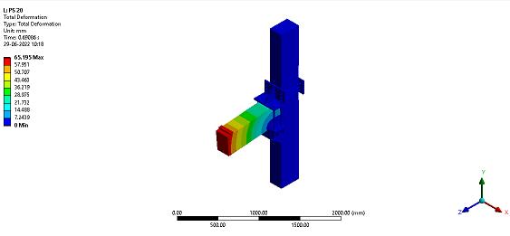
Fig 5: Totaldeformationofprecastbeam column joint
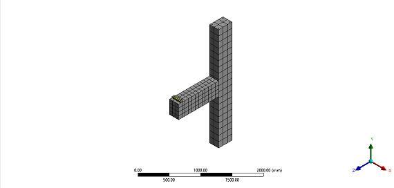
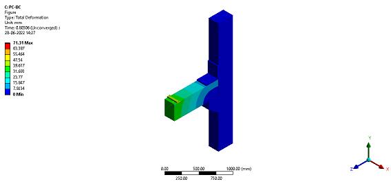
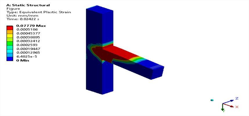
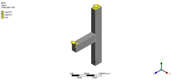
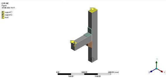
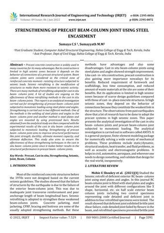
Fig 1: Monolithicbeam columnjointwithfixed supportsandloadingconditions
Fig-2: Meshingofmonolithicbeam columnjoint
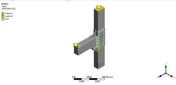
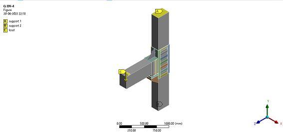
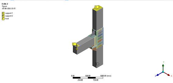
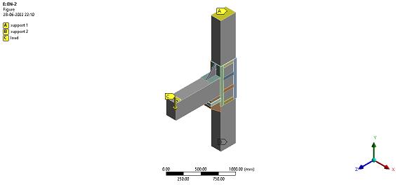
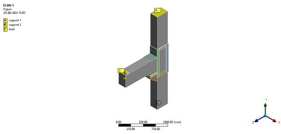
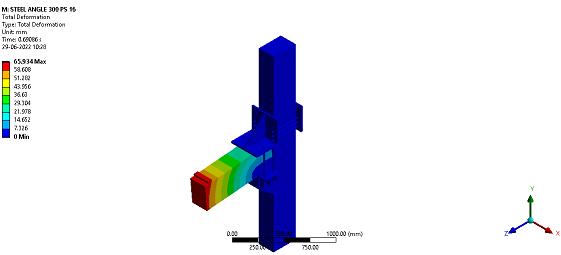
Inthisstudy,twotypesofstrengtheningmethods wereadopted.Oneofthemethodswastheweldingof steelplatesandanglestothebeam columnjoint. The parametricstudyadoptedherewaschangingnosteel plates.ThesemodelsarenamedEN1,EN2,EN3,EN4, andEN5 HorizontalandverticalSteelplatesusedinthe columnhavedimensionsof200X50mmand700X50 mmwithathicknessof10mm.Horizontalandvertical steelplatesusedinthebeamhavedimensionsof150x 50mmand360X50mmwithathicknessof10mm.A stiffenerplateusedinthecleatanglehasdimensionsof 190mmX190mmwithathicknessof20mm. Asteel platewithofwidth50mmandthicknessof10mmwas usedtocoverthecorbel.
Fig 3: Plasticstrainregionofmonolithicbeam columnjoint
Another strengthening method was steel plates andangleswereprestressedwithprestressingbarsand anchoring bolts. The first parametric study adopted herewaschangingthediameterofprestressingbars. Thediameterofprestressingbarsadoptedherewas16 mmand20mmwithacleatangledimensions180mm X180mmX20mm Theprestressingbarlengthusedin the column and beam were 400 mm and 450 mm respectively.Thebarswereprestresseduntilatension force approximately equal to 70 percent of the minimumtensilestrengthwasproducedinthebarsand the minimumtensilestrengthwastakenas1000MPa
International Research Journal of Engineering and Technology (IRJET) e ISSN: 2395 0056
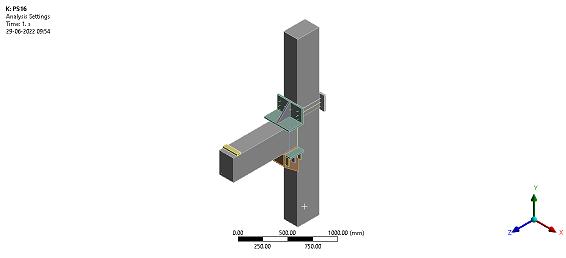
[3]. Accordingly, for 16 mm and 20 mm diameter prestressingbars,prestressingloadswastakenas140 KN and 219 KN respectively. The second parametric study was by adopting a 16 mm diameter bar, cleat angle dimension varied. The various cleat angle dimensionsadoptedwere225mm,250mm,275mm, and300mmwithathicknessof20mm.Thenotations andtheircorrespondingmodelnameisshowninthe Table3.
Fig 6: EN1Model
Fig-9: EN4Model
Fig 10: EN5Model Table-3: Notations and their corresponding model name
Name of model Notations
Diameterof prestressingbar (mm)
Fig-7: EN2Model
Fig-8: EN3Model
Cleatangle dimensions (mm)
PS16180 16 180X180X20
PS20180 20 180X180X20
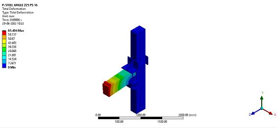
PS16225 16 225x225X20
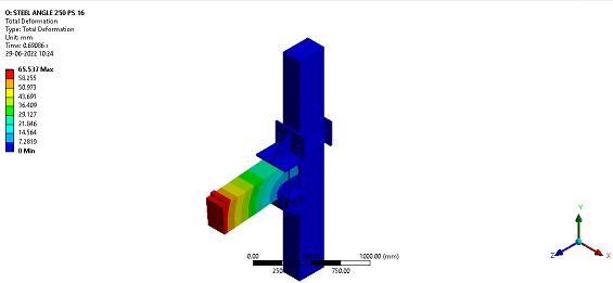
PS16250 16 250x250X20
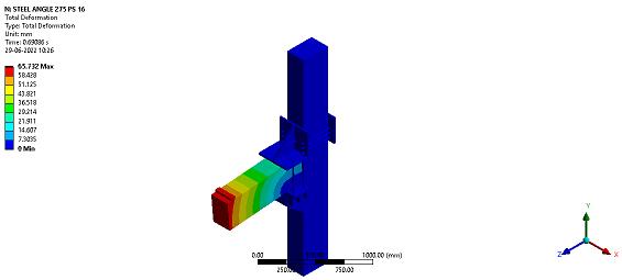
PS16275 16 275x275X20
PS16300 16 300x300X20
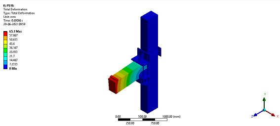
Fig 11: PS16180Model
Volume: 09 Issue: 06 | Jun 2022 www.irjet.net p ISSN: 2395 0072 © 2022, IRJET | Impact Factor value: 7.529 | ISO 9001:2008 Certified Journal | Page
International Research Journal of Engineering and Technology (IRJET) e ISSN: 2395 0056
Volume: 09 Issue: 06 | Jun 2022 www.irjet.net p ISSN: 2395 0072
Fig 17: TotaldeformationofPS16275Model
Fig 18: TotaldeformationofPS16300Model
The results obtained from the analysis of monolithic and precast beam column joint, strengtheningofprecastbeam columnjointbywelding ofsteelplatesandangles,andstrengtheningofprecast beam columnjointbyprestressingbarsistabulatedin theTable4,Table5,andTable6.Correspondingload deformationgraphisalsorepresentedbelow. Table-4: Analysisresultsofmonolithicbeam column jointandnonstrengthenedprecastbeam columnjoint Model Deform ation (mm)
Load (KN) Yield displac ement
Ductil ity
Monolithic beam column joint
53.48 42.66 4.91 10.88
40.79 74.24 11.17 3.65 Precast beam column joint
International Research Journal of Engineering and Technology (IRJET) e ISSN: 2395 0056
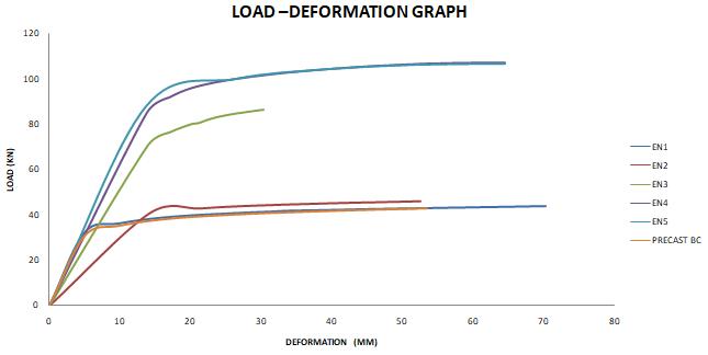
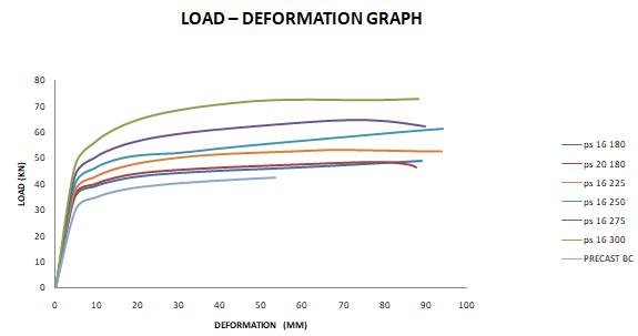
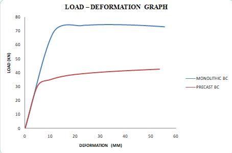
Fig-19: Loaddeformationgraphofmonolithicbeam column joint and non strengthened precast beam columnjoint
Table-5: Result of strengthening of precast beam columnjointbyweldingofsteelplatesandangles
Model Deforma tion (mm)
Precast beam column joint
Load (KN) Yield displ acem ent
ductilit y % incre ase in load
53.48 42.66 4.91 10.88
EN1 70.27 43.89 4.91 14.31 2.87 EN2 52.29 45.77 14.19 3.71 7.29 EN3 30.28 86.55 13.93 2.17 50.71 EN4 64.54 107.18 13.79 4.68 151.24 EN5 64.55 106.65 13.69 4.72 150.00
Fig-20: Loaddeformationgraphofnonstrengthened precast beam column joint model and strengthened modelsbyweldingofsteelplatesandangles.
Table 6: Result of strengthening of precast beam columnjointbyprestressingbarsandanchoringbolts. Model Defo rmati on (mm )
Precast beam column joint
Load (KN) Yield displace ment
ductilit y % incre ase in load
53.48 42.66 4.91 10.88
PS16180 93.64 49.39 4.69 19.95 15.77
PS20180 79.93 48.64 4.71 16.98 14.02
PS16225 93.99 52.70 4.70 20.01 23.53
PS16250 94.27 61.40 4.70 20.06 43.92
PS16275 94.51 61.53 4.70 20.10 44.23
PS16300 88.17 72.74 4.70 18.74 70.52
Fig 20: Loaddeformationgraphofnonstrengthened precast beam column joint model and strengthened modelsbyprestressingbarsandanchoringbolts.
Thisstudywasmainlyfocusedonthestructural performancelikeloadcarryingcapacity,jointstrength, ductility, ultimate moment capacity, and ultimate deflection.Theresultsaresummarizedasfollows:
Monolithic beam column joint have a higher loadcarryingcapacityabout74.24KNthanthe precast beam columnjoint. But in the case of ductility precast connection showed a higher value of about 10.88 compared to monolithic beam columnconnection.
Strengthening of precast beam column joint usingweldingofsteelplatesandanglesshowed improvementinloadcarryingcapacity.Among them,EN4modelshoweda151.24%increase inloadcarryingcapacitycomparedtothenon
Volume: 09 Issue: 06 | Jun 2022 www.irjet.net p ISSN: 2395 0072 © 2022, IRJET | Impact Factor value: 7.529 | ISO 9001:2008 Certified Journal | Page3396
International Research Journal of Engineering and Technology (IRJET)
e ISSN: 2395 0056
Volume: 09 Issue: 06 | Jun 2022 www.irjet.net p ISSN: 2395 0072
strengthenedprecastbeam columnconnection. Also EN1 model showed a 2.87% increase in load carrying capacity than the non strengthenedprecastbeam columnconnection and this one showed the least improvement. ExceptforEN1restoftheothermodelsshowed adecreaseinductilitywhencomparedtonon strengthenedprecastbeam columnconnection. EN1 showed maximum deformation of 70.27 mmamongallmodels.
Strengthening of precast beam column joint using prestressing bars and anchoring bolts also showed improvement in load carrying capacity.Theprecastbeamcolumnjointhaving a16mmdiameterprestressingbarshoweda 15.77%increaseinloadcarryingcapacitywhen compared with the non strengthened precast beam columnconnection. Themodelwith16 mm prestressing bar showed higher load carryingcapacitythanthemodelwith20mm prestressingbar.Thisresult,itshowsthatthere willbenostrengthimprovementbychanging theprestressingbardiameter.Sobytaking16 mm prestressing bar diameter, cleat angle dimensionschanged.Amongthem,PS16300 showed a 70.52 % increase in load carrying capacitythennonstrengthenedprecastbeam column joint. The model PS 16 275 showed higherductilityanddeformationcomparedto allmodels.
Fromtheanalysisofdifferentbeam columnjoint modelsfollowingconclusionscanbedrawn:
1. Monolithicbeam columnjointhavehigherload carrying capacity than precast beam column joint.
2. Strengtheningofprecastbeam columnjointby usingweldingofsteelplatesandanglesshowed improvementinjointstrengththanbyusingthe prestressingmethod.
3. These strengthening methods showed better results in precast connection. So these strengthening methods can use in weak monolithic beam column joint; thereby the effectivenessofthesestrengtheningmethodsin themonolithicbeam columnjointsisproved.
[1].MohieE.Shoukry,AhmedM.Tarabia,MahmoudZ. Abdelrahman,“SeismicretrofitofdeficientexteriorRC beam column joints using steel plates and angles”, AlexandriaEngineeringjournal,Vol.61,2022,pp3147 3164.
[2]. Jansi Rani K, Subathra.S,Sekar.A,” Experimental investigationonseismicretrofittingofRCCstructures”, IRJET,Vol.6,may2019,pp2395 0072.
[3].JalilShafaei,AbdollahHosseini,MohammdSadegh Marefat,” Seismic retrofit of external beam column joints by joint enlargement using prestressed steel angles”,Engineeringstructures,Vol.81, 2014, pp265 288.
[4].MohamedH.Mahmoud,HamdyM.Afefy,NesreenM. Kassem, Tarek M. Fawzy, “Strengthening defected beam columnjointsusingCFRP”,Journalofadvanced research,Vol.5,2014,pp67 77.
[5].R.VidjeapriyaandK.P.Jaya,”Experimentalstudy on two simple mechanical precast beam column connections under reverse cyclic loading”, journal of performanceofconstructedfacilities,Vol.27,July2013, pp402 414.
[6].Mitchell,D.,DeVall,R.H.,Saatcioglu,M.,Simpson, R.,Ti nawi,R.,andTremblay,R.(1995).“Damageto concrete structures due to the 1994 Northridge earthquake.”Can.J.Civ.Eng.,22(2),pp361 377.
[7].Gulkan,P.(1998).“TheCeyhan Misisearthquakeof 27 June 1998: A preliminary engineering reconnaissancereport.”TechnicalRep.No.METU/DMC 98 01, Disaster Management, Implementation and ResearchCenter,MiddleEastTechnicalUniv.,Ankara, Turkey.
Factor value: