DESIGN AND ANALYSIS OF MULTIFACE HYDRAULIC BENDING MACHINE DIE
1,2,3 UG Scholar, 4 Assistant Professor 1,2,3,4 Department of Mechanical Engineering, Sengunthar Engineering College(Autonomous), Tiruchengode, Namakkal, India. ***
ABSTRACT: TheprojectisaboutdesigningabendingdieforaHindustanHydraulicPressBrakemachine.Thecompanyis Craft Engineering, and it is located in Malumichampatty, Coimbatore. It has been assigned the project of designing and manufacturingtools.Theolddesignwasineffective.Thecomponentformerlyrequiredalargernumberofdiesforbending intheproductionprocess.Theproductioncycletimeisincreasing,whichnecessitatesgreaterroom.Variouscauseswere identified and solutions were developed using data gathered from the industry during this research. Component, formatting,style,styling,andinsertareallkeywords.

1. INTRODUCTION
Inmostcases,adieisinstalledinthepressbrakeduringbending.Thisisachannel likeportionthatisstationary. The bend that will be formed is defined by the outside shape of the die. With the use of clamps, a tool is mounted to the machine'sramandhasroundededgesthatproducethebend'sinteriorshape.Thebendingforceiscreatedbythepunch, which is a moving part. The tool descends, applying pressure to the sheet metal. When the pressure exceeds the plastic limitofthesheetmetal,thesheetmetalgoesthroughaplasticdeformationstageandtakestheshapeofthediebeneathit. Thepunchthengoesupwardsforthenextcycleoncetheprocessiscompleted.Thisisit.
2. MACHINE DIE METHOD
2.1. SHEET METAL BENDING
Theprocessofbendingametalistermedasbending.Sheetmetal,tubes,squarehollow,rod,andironangleareall optionsforthemetal.Thismetalhasathicknessofitsown.Several factorsaretakenintoaccountwhilebuildingbending machines,including the typeof metal,the typeof roller bender (powerormanual), andthesize ofthe bending machine. The capacity of the bending machine that can bend a sheet metal or tube is usually the only variation between different typesofbendingmachines.
2.2. NEED OF AUTOMATION
Themajorityofthesystemsdesignedforbendingdiesnecessitatetheassistanceofqualifiedandexperienceddie designers in making proper selections at various phases of process planning and die design. Most bending die design automation prototypes still suffer from the drawbacks of traditional expert system architecture and are unable to efficientlymanagediverseinformationsources.Many studieshavelookedinto usingthe finite elementmethod (FEM)to optimisebendingdiedesignparameters.Thesemethods,however,areimpracticablefortheplanninganddesignstagesof the deep drawing process due to the considerable calculation time and skill necessary to grasp the findings. Most sheet metal industries are currently experiencing a severe lack of experienced die designers. Furthermore, in the stamping industry, the mobility of experienced die designers has resulted in Sheet metal businesses all across the world are experiencingagreatdealofdifficulty.
2.3 V BENDING
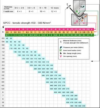
The most frequent punch and die bending method is Vbending. Bottoming, air bending, and coining are the three subgroups.Around90%ofallbendingjobsaredonewithairbendingandbottoming.Accordingtothematerialthicknesst,the tablebelowcanhelpyoudetermine theminimum flangelength b(mm)andinside radiiir(mm)(mm). Youmayalsoseethe requireddiewidthV(mm)forsuchspecs.Acertaintonnagepermetersisrequiredforeachprocess.Thisisdepictedinthetable
International Research Journal of Engineering and Technology (IRJET) e ISSN:2395 0056
Volume:
www.irjet.net
ISSN:2395 0072
aswell.Asyoucansee,thickermaterialsandnarrowerinteriorradiinecessitatehighertonnage.Thehighlightedoptionsaremetal bendingstandardsthatarerecommended.
3. MATERIAL SELECTION
3.1 TOOL STEEL
They're usually exceedingly hard, wear resistant, tough, and resistant to local overheating, and they're commonly manufacturedtomeetspecificservicerequirements.Toughness,wearresistance,andheatresistancearethethree.These three characteristics are built into the tool steel. Another quality of tool steel that is developed by the heat treatment processishardness.Toughnessreferstoasteel'sresistancetocracking,chipping,andbreaking.
3.2. 42CrMo STEEL
It's a medium carbon alloy structural steel with excellent mechanical qualities, hardenability, and a wide range of applications. It's commonly utilised in the machinery industry to make gears, connecting rods, high strength bolts, and othercriticalcomponents.Thisisaparticularhigh strengthsteelthatcanbequenchedandtempered.
3.3. 42CrMo MECHANICAL PROPERTIES
TensileStrength:nolessthan1080MPa.
YieldStrength:nolessthan930MPa.
Elongation:nolessthan12%
RateofReductionofArea:45%
ImpactAbsorbingEnergy:nolessthan63J.
Elasticmodulus:2.1e+11N/m^2
Poisson’sratio:0.28
Massdensity:7700kg/m^3
Shearmodulus:7.9e+10N/m^2
Thermalexpansioncoefficient:1.3e 05/Kelvin
International Research Journal of Engineering and Technology (IRJET) e ISSN:2395 0056
Volume: 09 Issue: 06 | June 2022 www.irjet.net p ISSN:2395 0072
4. MACHINE CALCULATIONS
4.1. BENDING FORCE
BF =KLσt(t)2 Newton W
K Tensilestrength
L-Bendinglength K Constant(K=1.33)
W Dieopening t Sheetthickness
Bendingforceforstainlesssteelmetal =1.33*50*600*(2)2 N 16
BF=9975N
Bendingforceforaluminiumsheetmetal =133*50*690*(2)2 N 16
BF =11471N
4.2. BEND ALLOWANCE
BA=2 A (R+Kba t)
360 where BA = bend allowance; A = bend angle; R= bend radius; t = stock thickness; and Kba is factor to estimatestretching
IfR<2t,Kba=0.33
IfR 2t,Kba=0.50
BA=2*(22/7)* 90 *(R+0.33*2) 360 R=W/6 =1.6/6 R=0.27 BA=6.2857*0.25*0.93
Bendingallowance=1.461
Volume: 09 Issue: 06 | June 2022 www.irjet.net p ISSN:2395 0072
5. PROBLEM IDENDIFICATION
Since the dies come in different sizes, we'll have to determine which work we'll accomplish and manually place thedieinthemachinebyworkers.Also,becausediesareheavy,twoorthreepeoplearerequiredtosecuretheminthedie holder. Because the machine has so many dies, it requires additional storage space and material. For operation, more workers are required. It has more time to replace and calibrate the machine's measurements. Change the material to withstandthesameloadwithlessvolumethanthecurrenttype
6. WORKING PRINCIPLE
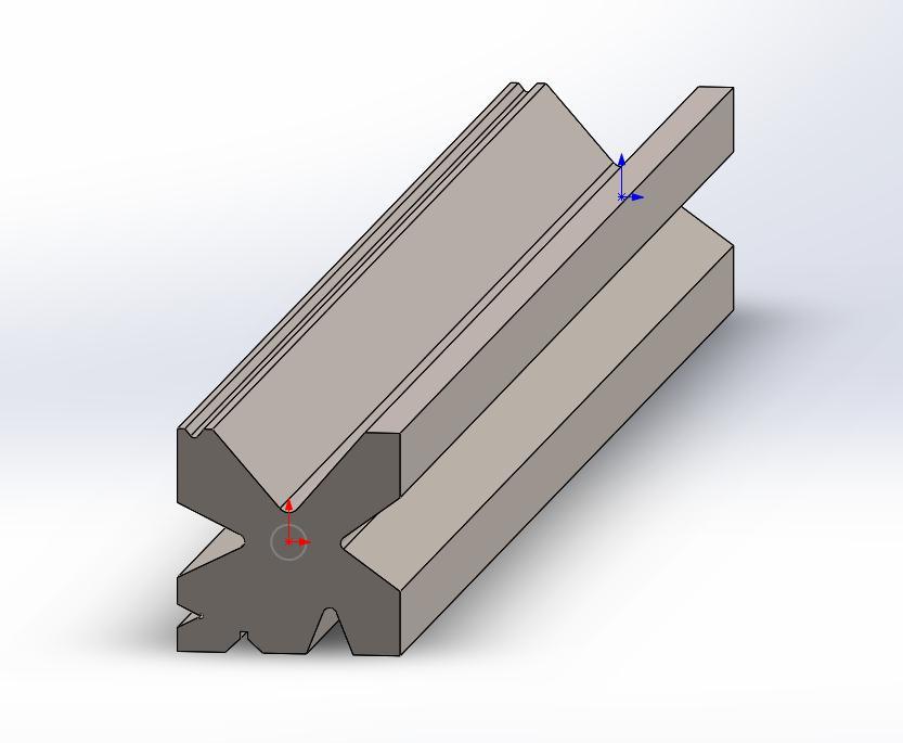
Initially, the fundamental design is drawn and fed into the bending machine's electronic controller, where the drawingisconvertedintonumericalcontrol.Thesheetmetalbendingvalueisalsosetinthecontroller.Thehydraulicunit, sensors,andotherdrivesinthemachineareallcontrolledbythecontroller.Nowadays,diescomeinmanysizesandtypes, thereforeamulti facebendingdieisconstructedandcomparedtoanolderoneinordertoendurethesamecapacity.The Multi face hydraulic press brake bending machine die works by reducing the amount of material used in the fabrication, use, and selection of sheet metal bending errors. It is a die that combines four or five separate dice into one. This die is better suited to common bending machine operations. A press brake die is a tool which is used to produce sheet metal usingapressbrake.Thistoolingismadeupofavariety ofparts,andeachtoolingismadeupofadifferentsetofparts.It primarily accomplishes the processing of component shape by altering the physical condition of the produced material.
V bendingisthemostpopularmethod,inwhichthepunchanddie are"V"shaped.Thepunchbendthesheetby forcingitintotheV "V"die'sshapedgroove."Airbending"occurswhenthepunchdoesnotdrivethesheettothebottom ofthediechamber,leaving spaceorairunderneath.Bendingtubeandtubeshapingrequirestheuseofbenddies,clamp dies,andpressuredies.Eachofthesesortsofdiesservesacertainpurpose.Bendingisdonewithadieanda punch.The bendingisknownasv bendingwhena v shapeddieandpunchareemployed.Edgebendingoccurswhena sheetisbent ontheedgeusingawipingdie.
7. INTRODUCTION OF FEM
In a variety of computer domains, the FEM is a mathematical model for predicting near experimental answers. FiniteelementanalysisisthetermgiventonumericalanalysisbasedonFEM(FEA).
7.1. FEA WORKS
FEA could be used in engineering as a machine tool for performing arts engineering analysis. It involves using mesh construction techniques to break down a large problem into smaller components, as well as using a software packageprogramthatadherestotheFEMrule.
Volume: 09 Issue: 06 | June 2022 www.irjet.net p ISSN:2395 0072
7.2. ADVANTAGES OF FEA SOFTWARE
• It decreases the number of prototype testing, saving both money and time; and it displays the results of the study in a graphicalformat.
•Finiteelementmodellingandanalysisarecarriedoutinthepre processorandsolutionphases,whichwouldtakealong timeand,insomecases,beimpossibletocarryoutmanually.
•Itaidsintheoptimizationofadesign.
7.3. PROCEDURE ANALYSIS
ANSYS is a finite element modelling software system that may be used to numerically solve a variety of mechanicalissues.Amongotherthings,itwillperformstructural(linearandnon linear),thermal,magneticattraction,and fluid analysis. Analysis is made simple thanks to the user interface technique. The software system is given a graphical interfacetomakeiteasiertouse.
Theanswerofafiniteelementanalysiscanbeseparatedintothreestages: a. Pre processingstages b. Solution c. Postprocessing
7.4. PRE-PROCESSING STAGE
Thefollowingmajorstepsareengagedinthepre processingstage: 1. ImportorCreategeometry
Defineelementtype&realconstants
Definematerialproperties
Themeshingoflines/areas/volumes
7.5. POST PROCESSING
•Examiningtheanalysisfindingstoseehowtheappliedloadsaffectourdesignisoneofthemostcriticalphases. •Withthispost processor,wecanseetemperaturedistributionandheatflux,amongmanyotherthings.
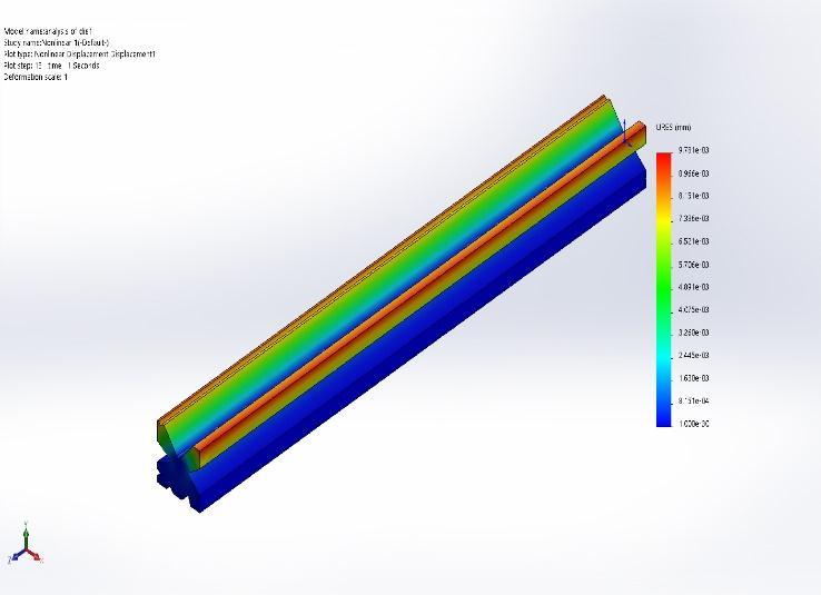
8. RESULTS
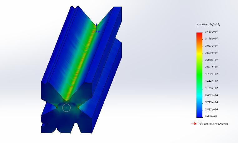
NAME TYPE MIN MAX STAIN ESTRN: EQUIVALENT STRAINATSTEP 983e 08 Element:2125 1.048e 04 Element:9454 STRESS VON: VON MISES STRESS ATSTEP 8.640e 01N/m^2 Node:11040 3.465e+07N/m^2 Node:450 DISPLACEMENT RESULTANT DISPLACEMENTATSTEP 0.000e+00mm Node:889 9.781e 03mm Node:9279
Volume: 09 Issue: 06 | June 2022 www.irjet.net p ISSN:2395 0072
8. CONCLUSIONS
Wecanseehowcrucialthebendingdieprocessisinthemanufacturingindustry.Theobjectiveofthisthesisisto determinethestressandstrainonthesheetasthetoolpressesittowardthedie.Asimplesheetdesignwithpiercingand shape forming features was considered. The deformation of all materials is the same after the simulation, however the stress of one material is larger than that of other materials with thickness. When comparing the same thickness with differentmaterials,theinfluenceonstressandstrainislarger.
ACKNOWLEDGEMENT
Thedesignanddevelopmentofbendingdieshasbeenafascinatingsubjectforbendingdieresearch,encouraging one'smindtoreachnewheightsinthemechanicalengineeringsector.Mr.sendhilvelan,B.E.,ourcompany'sprojectguide, forhisgreatassistanceandsharingofhisindustrialexpertise.Thisknowledgewillconstantlymotivateustocompleteour tasksflawlesslyandprofessionally.
REFERENCES
1. R. Hambli, S. Richir, P. Crubleau, and B. Taravel, (2003), “Prediction of optimum clearance in sheet metal blanking processes”.InternationalJournalofAdvancedManufacturingTechnology,Vol.22,pageno.20 25.
2. Emad Al Momani, Ibrahim Rawabdeh, (Mar. 2008), “An Application of Finite Element Method and Design of Experiments in the Optimization of Sheet Metal Blanking Process” Jordan Journal of Mechanical and Industrial Engineering.Volume2,Number1,Pages53 63.
3. RupaliChavanandNavneetPatil.“Design,DevelopmentandAnalysisofPressToolforanIndustrialPart”,International JournalofMechanicalandIndustrialTechnology,4(2016):112 123
4. L.Guo qingandW.Mao ting,“LightIndustryMachinery”,vol.29,no.2,(2011),pp.116 119.
5. Ketankapse,ajinkyajadhavDesignofblankingdieforstiffeningrib:AcasestudyIJRSETVol.6,Issue2,February