International Research Journal of Engineering and Technology (IRJET) e ISSN: 2395 0056

Volume: 09 Issue: 06 | Jun 2022 www.irjet.net p ISSN: 2395 0072
International Research Journal of Engineering and Technology (IRJET) e ISSN: 2395 0056
Volume: 09 Issue: 06 | Jun 2022 www.irjet.net p ISSN: 2395 0072
2
Abstract Recently, strengthening of steel sections using various fibre reinforced polymer (FRP) has come to the attention of many researchers. The deficiencyinsteelmembers may be due to the errors caused by construction, corrosion, fatigue cracking, andother reasons. This studyinvestigates the behaviour of circular hollow section (CHS) and square hollow section (SHS) steel members, comparing them with and without deficiency and strengthening the most load carrying capacity steel section by using HYBRID FRP composites under compressive, tensile, torsion and seismic loadings. To analyse the steel members, three dimensional (3D) modeling and nonlinear static analysis methods were applied, using ANSYS software. The results expected is that the HYBRID FRP composites strengthening on the most load carrying capacity steel section had an impact on raising the ultimate capacity of deficient steel members and could recover the strength lost due to deficiency
Key Words: Fiber Reinforced Polymer, Deficiency, CHS, SHS, Strengthening, Hybrid FRP composites
Strengthening of existing steel structures built within the lastdecadesisoneofthemostimportantissuesconsidered by structural engineers. Steel structures built in the past often need to be strengthened due to increased life loads, repairduetocorrosion,fatiguecracking,andotherreasons. Inrecentyears,FRPcomposites,asastrengtheningmaterial of steel structures, has attracted greater attention. Fiber reinforced polymer (FRP) has been a practical alternative constructionmaterialforreplacingsteelintheconstruction industry for several decades. The advantages of hybrid structural systems include the cost effectiveness and the ability to optimize the cross section based on material properties Thisstudyinvestigatesthebehaviourofcircular hollowsection(CHS)andsquarehollowsection(SHS)steel members,comparingthemwithandwithoutdeficiencyand strengthening the most load carrying capacity section by HYBRIDFRPcompositesundercompressive,tensile,torsion andseismicloadings.Toanalysethesteelmembers,three dimensional (3D) modeling and nonlinear static analysis methodswereapplied,usingANSYSsoftware
***
A H Kheykha (2020)[1] studied the “Strengthening of Deficient Steel Sections using CFRP Composite under CombinedLoading”inwhichheinvestigatedthebehaviorof deficient square hollow section (SHS) steel members strengthened by CFRP sheets under two types of the combinedloads.TostudytheeffectofCFRPstrengtheningon the structural behavior of the deficient steel members, 17 specimens, 12 of which were strengthened using CFRP sheets,wereanalyzed.Toanalyzethesteelmembers,three dimensional (3D) modeling and nonlinear static analysis methods were applied, using ANSYS software. The results showedthatCFRPstrengtheninghadanimpactonraisingthe ultimate capacity of deficient steel members and could recoverthestrengthlostduetodeficiency,andtheimpactof CFRP strengthening on rising and recovering the ultimate capacity of the steel members under loading scenario 2(combined torsion and tension) was more than the steel members under scenario 1(combined compression and torsion)
A.H Kheykha (2020)[2] studied “The effect of CFRP strengtheningonthebehaviorofdeficientsteelbeamsunder concentrated and distributed loading” in which he investigated the behavior and performance of CFRP strengtheneddeficientSHSsteelbeamsunderconcentrated anddistributedloads.Finiteelementmethod(FEM),using ANSYS,hasbeenemployedformodelingofsteelbeams.Ten steel beams, two non strengthened steel beams and eight CFRP strengthened steel beams have been analyzed. The results indicate the dimensions and number of composite layersisbeingeffectiveontheultimatecapacityoftheSHS steel beams. Also, the results have shown that in deficient steelbeamsCFRPcansignificantlyberecoveredthestrength lostduetodeficiency.
A.H Kheykha (2020)[3] studied the“Carbon fibre strengthening of deficient hollow steel sections under combined loading”. Most previous research studies have studiedthebehaviourofstructuralsteelmemberswithout deficienciessuchascracksandholes Theworkdescribedin thispaperisabouttheeffectofCFRPstrengtheningonthe structuralbehaviourofSHSsteelmembershavinganinitial deficiencyundercombinedaxialandlateralload.Tostudy theeffectsofthestrengthening,17specimensweretested,
International Research Journal of Engineering and Technology (IRJET) e ISSN: 2395 0056
with 12 specimens strengthened using CFRP sheets. The deficiencywascreatedbycuttingverticalorhorizontalslots inoneflange.Three dimensionalmodellingandnon linear staticanalyseswereusedtoanalysethesteelmembers.The resultsshowedthatthestrengtheningsignificantlyimproved theultimatecapacityofthedeficientsteelmembersandthe effectofatransversedeficiencyontheultimatecapacityof the steel members was greater than the effect of a longitudinaldeficiency.
A.H Kheykha (2018)[4] studiedthe“BehaviourofDeficient Steel MembersStrengthenedUsingCFRPUnderCombined Compressive Load and Torsional Moment” in which he exploredtheeffectofCFRPstrengtheningonthestructural behaviors of square hollow sections (SHS) steel members havinginitialdeficienciesundercombinedcompressiveload and torsional moment. In this study, 17 specimens were analyzed.Toanalyzethespecimens,threedimensional(3D) modellingandnonlinearstaticanalysisusingANSYSsoftware wereapplied.TheresultsindicatedthatapplicationofCFRP sheets for the strengthening of the deficient hollow steel members under combined compressive loadand torsional moment could recover the strength lost due to deficiency, significantly.
Nadim I Shbeeb, Rajai Al Rousan (2018)[5] studied the “Impact of bonded carbon fibre composite on the shear strengthofreinforcedconcretebeams”inwhichtheystudied to determine the effectiveness of using externally bonded CFRPcompositesheetsasamethodofincreasingtheshear strength of reinforced concrete beams. The investigated parameters were the amount and distribution of the composite, the bonded surface and fibre orientation. The overallbehaviourofthetestbeamsuptofailure,theonsetof cracking and crack development with increased load and ductility were recorded. Depending on the variables investigated,theexternallybondedcompositeincreasedthe shearcapacityby34 75%comparedwithotherbeams.Some previouslypublishedmodelsfoundtogiveconsistentlygood correlationswiththetestdata,withacceptablecoefficientsof variation.
A.H Kheykha (2017)[6] studied the “Numerical investigation on the behavior of SHS steel frames strengthened using CFRP”. This study explored the use of CFRPcompositeonretrofittingsquarehollowsection(SHS) steel frames, using numerical investigations. Ten Finite Element(FE)models,werestrengthenedwithCFRPsheets, were analyzed under different coveragelength, numberof layers, and location of CFRP composite. One FE model withoutstrengtheningwasanalyzedasacontrolFEmodelto determine the increase of the ultimate load in the strengthened steel frames. ANSYS software was used to analyze the SHS steel frames. The results showed that the coveragelengthandthenumberoflayersofCFRPcomposite haveasignificanteffectonincreasingtheultimateloadofthe SHSsteelframes.Theresultsalsoshowedthatthelocationof CFRP composite had no similar effect on increasing the
ultimateloadandtheamountofmidspandeflectionofthe SHSsteelframes.
A H Kheykha, Masoud Nekooi, Reza Rahgozar (2016)[7] studiedthe“AnalysisandstrengtheningofSHSsteelcolumns usingCFRPcompositematerials”inwhichtheyexploredthe useofflexibleadhesivelybondedCFRPsheetsinretrofitting slender SHS steel columns by numerical and analytical investigations.Thefiniteelementmethod(FEM)wasusedfor modeling.ANSYSwasemployedfortheanalysisofsamples. To determine the critical load of SHS steel columns, 15 samples, strengthened with CFRP, were analyzed under different support conditions. The results showed that the supportconditionandtheCFRPcoverageareeffectiveinthe criticalloadofcolumns.
1.TostudytheperformanceofCHS(CircularHollowSections) withoutdamageunderaxial,tensileandtorsionalloadings.
2.To study the performance of CHS with damage (25% surface corrosion) along 25% of total height under axial, tensileandtorsionalloadings.
3.TostudytheperformanceofSHS(SquareHollowSections) withoutdamageunderaxial,tensileandtorsionalloadings.
4.To study the performance of SHS with damage (25% surface corrosion) along 25% of total height under axial, tensileandtorsionalloadings.
5.Tofindthemostloadcarryingcapacitysection.
6.Proposing the effective method (2 layer or 4 layers of HybridFRP)ofstrengtheningthedeficientbeam.
7.Toperformtheseismicanalysisofmultistoreyframeunder deficiency conditions at the corner of the column and strengtheningandimprovingtheperformance.
1.TheworkislimitedtomodellingandanalysisofCHSand SHSwithhybridcompositesFRPusingANSYSsoftware.
Table -1: Dimensionsof CircularHollowSection(CHS)
Diameter 101.6mm
Thickness 4.8mm
Area 1460mm²
Height 1800mm
Volume: 09 Issue: 06 | Jun 2022 www.irjet.net p ISSN: 2395 0072 © 2022, IRJET | Impact Factor value: 7.529 | ISO 9001:2008 Certified Journal | Page3366
International Research Journal of Engineering and Technology (IRJET) e ISSN: 2395 0056
Crosssectional dimension 100x100x4mm
Area 1495mm²
Height 1800mm
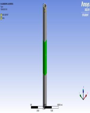
Square Hollow Section and Circular Hollow Section are analysedwithoutcorrosionandwithsurfacecorrosionunder loading types Compression, Tension and Torsion. The maximumloadcarryingcapacitymemberisselectedforthe nextpartoftheanalysis.ItisthenanalysedunderSeismic loadinginamulti storeyedframe.Forthecompensationof strength lost, the steel members are strengthened using 2 layersand4layersofhybridFRPcompositeswhichconsists ofAramidandGlassfibre.ThedimensionsforCHSistaken fromIS1161(1998)andthedimensionsforSHSistakenfrom IS4923(1997).25%oftheSurfacecorrosionisgivenin25% ofthetotalheightofthesection(25%of1800mm=450mm). Here, corrosion is given in the middle section. After corrosion,thicknessinthemiddleportionofSHS=4 (25%of 4)=3mm.Aftercorrosion,thicknessinthemiddleportionof CHS=4.8 (25%of4.8)=3.6mm.
Table 3: ModelnamesindetailforCompressionloading
Model name Names in detail
CLSQ CompressionloadinginSquare HollowSection
CLSQWITHSC
CompressionloadinginSquare HollowSectionwithSurface Corrosion
CLCS CompressionloadinginCircular HollowSection
CLCSWITHSC CompressionloadinginCircular HollowSectionwithSurface Corrosion
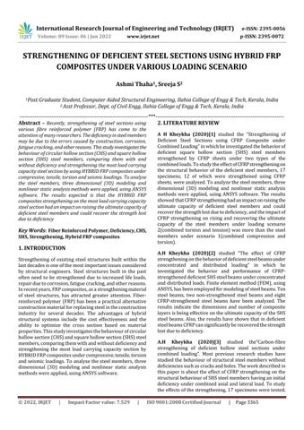
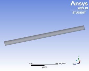
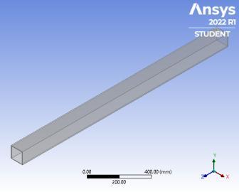
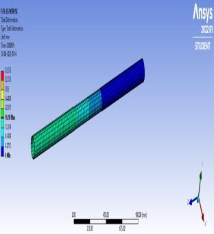
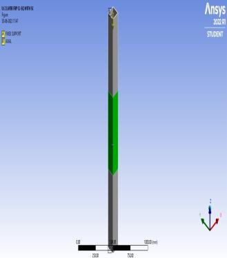
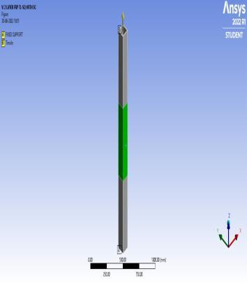
Fig-1: SHSandCHSmodelswithoutcorrosion
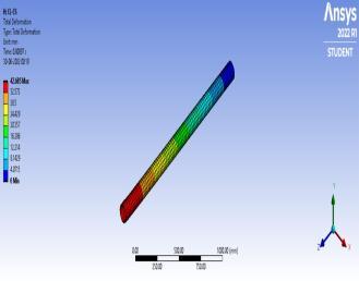
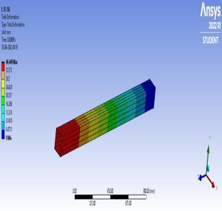
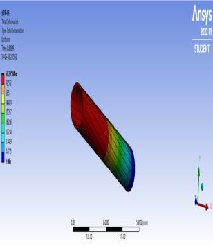
Fig 3: TotaldeformationfiguresofSHSandCHSwithout corrosionundercompressionloading
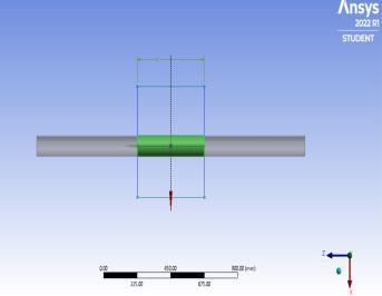
Fig 2: SHSandCHSmodelswithsurfacecorrosion
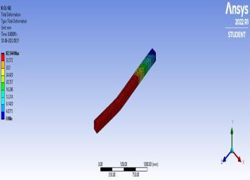
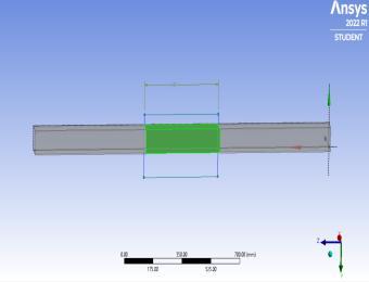
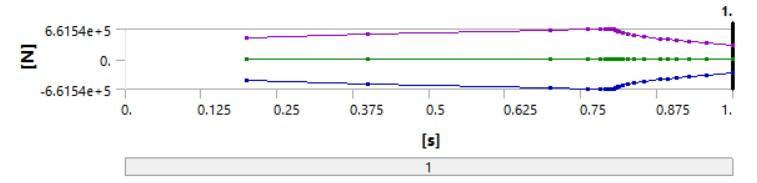
Square Hollow Section (SHS) and Circular Hollow Section (CHS)undercompressionloadingisanalysedusingANSYS Software.Surfacecorrosionisgiveninthemiddleportionof the total height. Models with and without corrosion is analysedintheANSYSsoftware.Modelnamesaregivenin thetableasfollows:
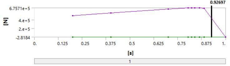
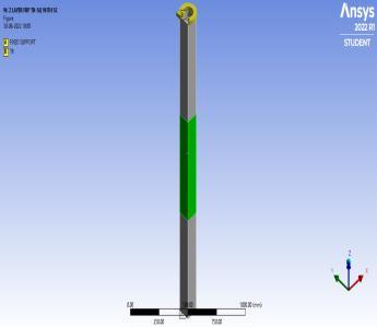
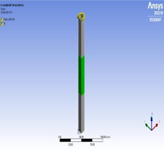
Fig 4: AxialloadingdiagramofSHSwithoutcorrosion
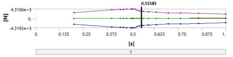
Fig 5: AxialloadingdiagramofCHSwithoutcorrosion
Volume: 09 Issue: 06 | Jun 2022 www.irjet.net p ISSN: 2395 0072 © 2022, IRJET | Impact Factor value: 7.529 | ISO 9001:2008 Certified Journal | Page3367
International Research Journal of Engineering and Technology (IRJET) e ISSN: 2395 0056
5.2
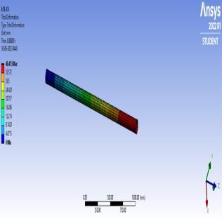
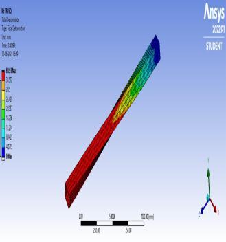
Square Hollow Section (SHS) and Circular Hollow Section (CHS) under tensile loading is analysed using ANSYS Software.Surfacecorrosionisgiveninthemiddleportionof the total height. Models with and without corrosion is analysedintheANSYSsoftware.Modelnamesaregivenin thetableasfollows:
Table 5: Modelnamesindetailfortensileloading
Model name Names in detail
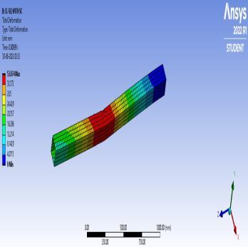
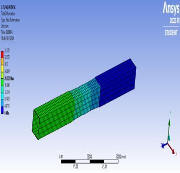
Fig-6: TotaldeformationfiguresofSHSandCHSwith surfacecorrosionundercompressionloading
TLSQ TensileloadinginSquare HollowSection
TLSQWITHSC TensileloadinginSquare HollowSectionwithSurface Corrosion
TLCS TensileloadinginCircular HollowSection
TLCSWITHSC TensileloadinginCircular HollowSectionwithSurface Corrosion
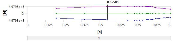
Fig 7: AxialloadingdiagramofSHSwithsurfacecorrosion
Fig 9: TotaldeformationfiguresofSHSandCHSwithout corrosionundertensileloading
Fig 8: AxialloadingdiagramofCHSwithsurfacecorrosion
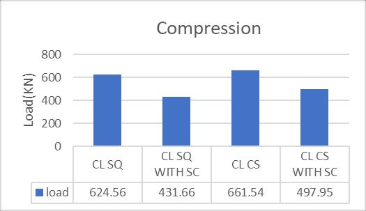
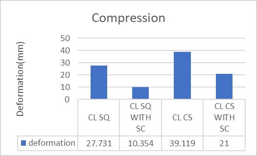
Table 4: ComparisontableofSHSandCHSunder compressionloading
Load type Models Deformation (mm) Load (KN)
Compression CLSQ 27.731 624.56
Compression CLSQWITH SC 10.354 431.66
Compression CLCS 39.119 661.54
Compression CLCSWITH SC 21 497.95
Fig 10: TensileloadingdiagramofSHSwithoutcorrosion
Volume: 09 Issue: 06 | Jun 2022 www.irjet.net p ISSN: 2395 0072 © 2022, IRJET | Impact Factor value: 7.529 | ISO 9001:2008 Certified Journal | Page3368
International Research Journal of Engineering and Technology (IRJET) e ISSN: 2395 0056
Volume: 09 Issue: 06 | Jun 2022 www.irjet.net p ISSN: 2395 0072
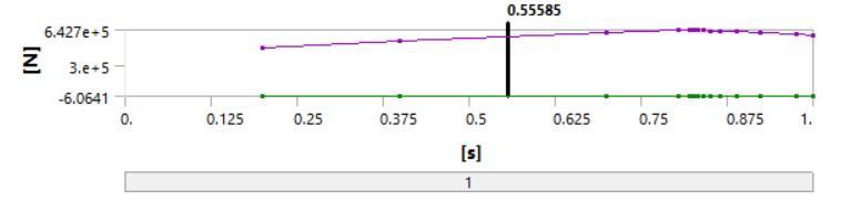
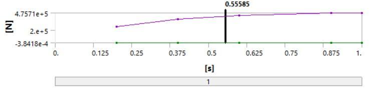
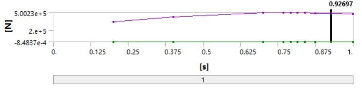
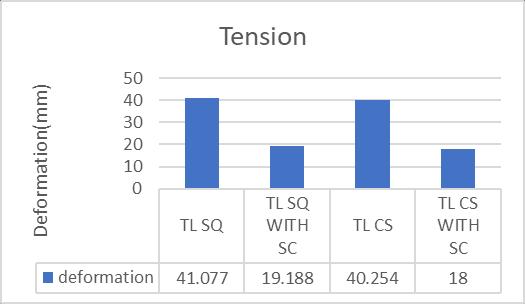
Table 6: ComparisontableofSHSandCHSundertensile loading
Load type Models Deformation (mm) Load (KN)
Tension TLSQ 41.077 675.71
Tension TLSQWITHSC 19.188 500.23
Tension TLCS 40.254 642.7
Fig-11: TensileloadingdiagramofCHSwithout corrosion
Tension TLCSWITHSC 18 475.71
Square Hollow Section (SHS) and Circular Hollow Section (CHS) under torsional loading is analysed using ANSYS Software.Surfacecorrosionisgiveninthemiddleportionof the total height. Models with and without corrosion is analysedintheANSYSsoftware.Modelnamesaregivenin thetableasfollows:
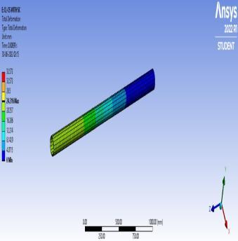
Fig 12: TotaldeformationfiguresofSHSandCHSwith surfacecorrosionundertensileloading
Table 7: Modelnamesindetailfortorsionalloading Model name Names in detail
TRSQ TorsionalloadinginSquare HollowSection
TRSQWITH SC TorsionalloadinginSquare HollowSectionwithSurface Corrosion
TRCS TorsionalloadinginCircular HollowSection
Fig 13: TensileloadingdiagramofSHSwithsurface corrosion
TRCSWITH SC TorsionalloadinginCircular HollowSectionwithSurface Corrosion
Fig-14: TensileloadingdiagramofCHSwithsurface corrosion
Fig 15: TotaldeformationfiguresofSHSandCHSwithout corrosionundertorsionalloading
International Research Journal of Engineering and Technology (IRJET) e ISSN: 2395 0056
Volume: 09 Issue: 06 | Jun 2022 www.irjet.net p ISSN: 2395 0072
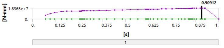
Fig 16: TorsionalloadingdiagramofSHSwithout corrosion
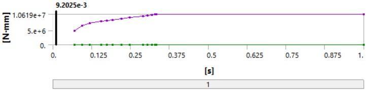
Fig 20: TorsionalloadingdiagramofCHSwithsurface corrosion
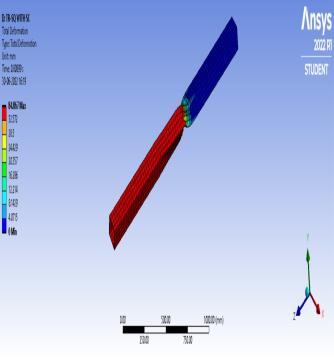
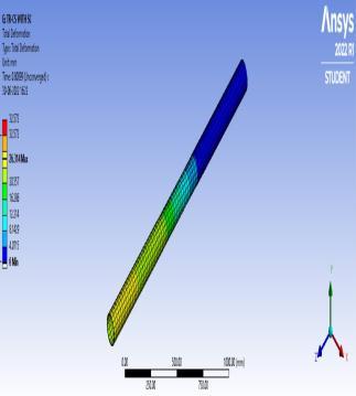
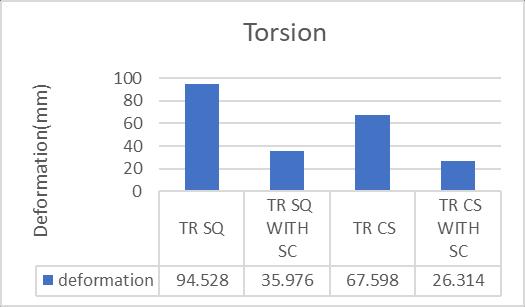
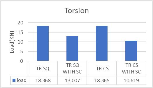
Table 8: ComparisontableofSHSandCHSundertorsional loading
Load type Models Deformation (mm) Load (KNm)
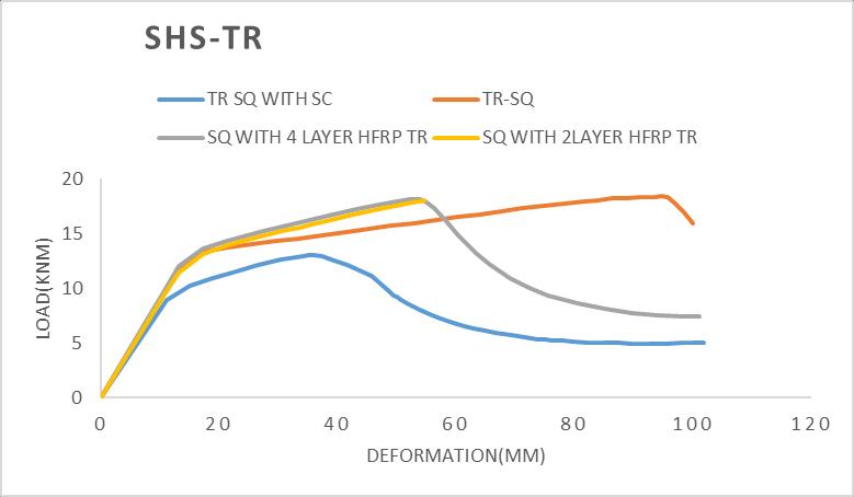
Torsion TRSQ 94.528 18.368
Torsion TRSQWITHSC 35.976 13.007
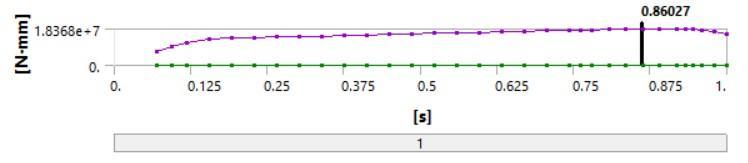
Torsion TRCS 67.598 18.365
Torsion TRCSWITHSC 26.314 10.619
Fig 17: TorsionalloadingdiagramofCHSwithout corrosion
Considertheloaddeformationrelationshipgraphsofloading typescompression,tensionandtorsiongivenasfollows:
Fig 18: TotaldeformationfiguresofSHSandCHSwith surfacecorrosionundertorsionalloading
Fig 19: TorsionalloadingdiagramofSHSwithsurface corrosion
600
CL SQ WITH SC
Load(KN)
400
200
Load(KN) Deformation(mm)
800 0 50 100 150
0
CL CS WITH SC CL-CS CL-SQ
Fig 21: Load deformationrelationshipgraphofCHSand SHSundercompressionloading
800
600
400
200
0
0 20 40 60
Deformation(mm)
TL SQ WITH SC
TL CS WITH SC TL-CS
TL-SQ
Fig-22: Load deformationrelationshipgraphofCHS and SHSundertensileloading
© 2022, IRJET | Impact Factor value: 7.529 | ISO 9001:2008 Certified Journal | Page3370
International Research Journal of Engineering and Technology (IRJET) e ISSN: 2395 0056
Load(KN)
0 5 10 15 20 0 50 100 150
Deformation(mm)
TR SQ WITH SC
TR CS WITH SC
TR-CS TR-SQ
Fig-23: Load deformationrelationshipgraphofCHSand SHSundertorsionalloading
Consider the comparsion charts of load and deformation cases of SHS and CHS under loading types compression, tensionandtorsiongivenasfollows:
Load(KN)
0 200 400 600 800
Fig-24: LoadcomparisonchartofCHSandSHSunder compressionloading
TL SQ TL SQ WITH SC TL CS TL CS WITH SC load 675.71 500.23 642.7 475.71
Fig 26: LoadcomparisonchartofCHSandSHSunder tensileloading
Fig 25: DeformationcomparisonchartofCHSandSHS undercompressionloading
Fig-27: DeformationcomparisonchartofCHSandSHS undertensileloading
Fig 28: LoadcomparisonchartofCHSandSHSunder torsionalloading
Volume: 09 Issue: 06 | Jun 2022 www.irjet.net p ISSN: 2395 0072 © 2022, IRJET | Impact Factor value: 7.529 | ISO 9001:2008 Certified Journal | Page3371
International Research Journal of Engineering and Technology (IRJET) e ISSN: 2395 0056
Volume: 09 Issue: 06 | Jun 2022 www.irjet.net p ISSN: 2395 0072
Table 9: MaterialpropertiesofGFRPusedinthestudy
Property Dimension
Modulusofelasticity 71,000N/mm²
TensileStrength 2000N/mm² Thickness 0.17mm
Fig 29: DeformationcomparisonchartofCHSandSHS undertorsionalloading
Fromthecomparisonchartsofloadinganddeformation and also considering the load deformation relationship graphs of all 3loading types, it is concluded that the most loadcarryingcapacitysteelsectionisSquareHollowSection (SHS). Hence, for the further analysis of the work, SHS is chosen. Wrapping of SHS in 2 and 4 layers of Hybrid FRP Compositesiscarriedout.Seismicanalysisstudyofamulti storeyed frame is also carried out. It is also strengthened usingHybridFRPCompositesin2and4layers
Fiber reinforced polymer (FRP) has been a practical alternative construction material for replacing steel in the constructionindustryforseveraldecades.Theadvantagesof hybridstructuralsystemsincludesthecosteffectivenessthe ability to optimize the cross section based on material properties.ThehybridFRPcompositeshavebeenprepared to enhance the mechanical, thermal, damping properties comparedtosingleFRPcomposites.AmongthetypesofFRP compositesavailableinthemarket,GlassandAramidarethe twotypesoffiberswhichareusedforstrengtheninginthis study
Glass Fibre Reinforced Polymer (GFRP): Glass fibres are basicallymadebymixingsilicasand,limestone,folicacidand other minor ingredients. Glass is generally a good impact resistant fibre but weighs more than aramid. Glass fibres haveexcellentcharacteristicsequaltoorbetterthansteelin certainforms ThematerialpropertiesofGFRPusedinthis studyaregiveninthetableasfollows:
Aramid Fibre Reinforced Polymer (AFRP): Aramid is the shortformforaromaticpolyamide.Theirmainadvantages overcommonreinforcingsteelrebarsrelyontheirlightness, durabilityperformancesand mechanical properties. Here, 1414 Kevlar fabric is used for the study The material propertiesofGFRPusedinthisstudyaregiveninthetableas follows:
Table 10: MaterialpropertiesofAFRPusedinthestudy
Property Dimension
Modulusofelasticity 60,000N/mm² TensileStrength 2400N/mm² Thickness 0.26mm
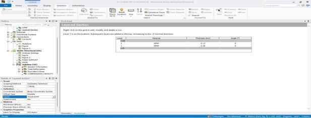

6.2 Wrapping Hybrid FRP (2 and 4 layers) in SHS
HybridFRPCompositesconsistingofAramidandGlass each one by one is assigned in the worksheet of ANSYS Software.ScreenshotoftheHybridFRPcompositesgivenin2 layersand4layersisgivenbelow:
Fig 30: HybridFRPgivenin2layersinworksheetin ANSYSworkbench
Fig 31: HybridFRPgivenin4layersinworksheetin ANSYSworkbench
International Research Journal of Engineering and Technology (IRJET) e ISSN: 2395 0056
Volume: 09 Issue: 06 | Jun 2022 www.irjet.net p ISSN: 2395 0072
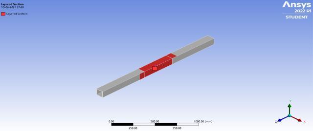
Fig 32: HybridFRPwrappedin2and4layersinSHS
6.2.1Compression loading
Model names designated for compression loading are givenasfollows:
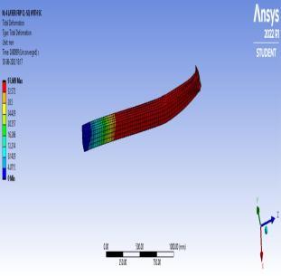
Table 11: Modelnamesindetailforcompressionloading
Model name Names in detail
CLSQ CompressionloadinginSquare HollowSection
CLSQWITHSC CompressionloadinginSquare HollowSectionwithSurface Corrosion
4LAYERFRPCLSQ WITHSC HybridFRPwrappedin4layersin Squarehollowsectionin compressionloading
2LAYERFRPCLSQ WITHSC HybridFRPwrappedin2layersin Squarehollowsectionin compressionloading
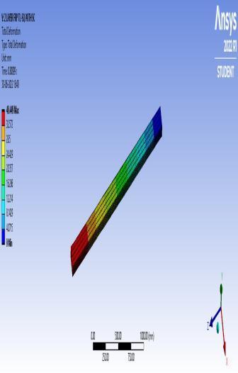
Fig-34: TotaldeformationfiguresofSHSwrappedin2and 4layersofhybridFRPundercompressionloading
Fig 33: BoundaryconditionofSHSwrappedin2and4 layersofhybridFRPundercompressionloading
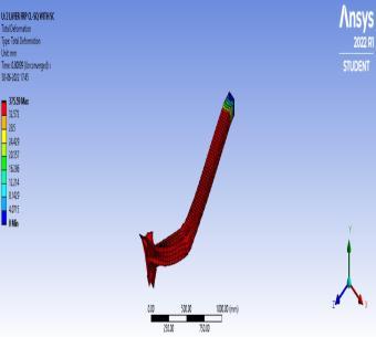
Fig 35: LoadingdiagramsofSHSwrappedin2and4layers ofhybridFRPundercompressionloading
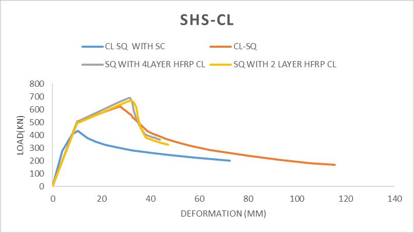
Table 12: ComparisontableofSHSwrappedin2and4 layersofhybridFRPundercompressionloading
Load type Models Deformation (mm) Load (KN)
Compression CLSQ 27.731 624.56
Compression CLSQWITHSC 10.354 431.66
Compression 4LAYERFRPCL SQWITHSC 31.487 688.96
Compression 2LAYERFRPCL SQWITHSC 32.318 670.09
6.2.2 Tensile loading
Model names designated for tensile loading are given as follows:
Table 13: Modelnamesindetailfortensileloading
Model name Names in detail
TLSQ TensileloadinginSquareHollow Section
TLSQWITHSC TensileloadinginSquareHollow SectionwithSurfaceCorrosion
© 2022, IRJET | Impact Factor value: 7.529 | ISO 9001:2008 Certified Journal | Page3373
International Research Journal of Engineering and Technology (IRJET)
e ISSN: 2395 0056
Volume: 09 Issue: 06 | Jun 2022 www.irjet.net p ISSN: 2395 0072
4LAYERFRPTLSQ WITHSC HybridFRPwrappedin4layersin Squarehollowsectionintensile loading
2LAYERFRPTLSQ WITHSC HybridFRPwrappedin2layersin Squarehollowsectionintensile loading
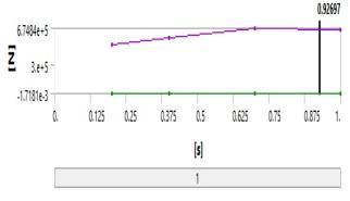
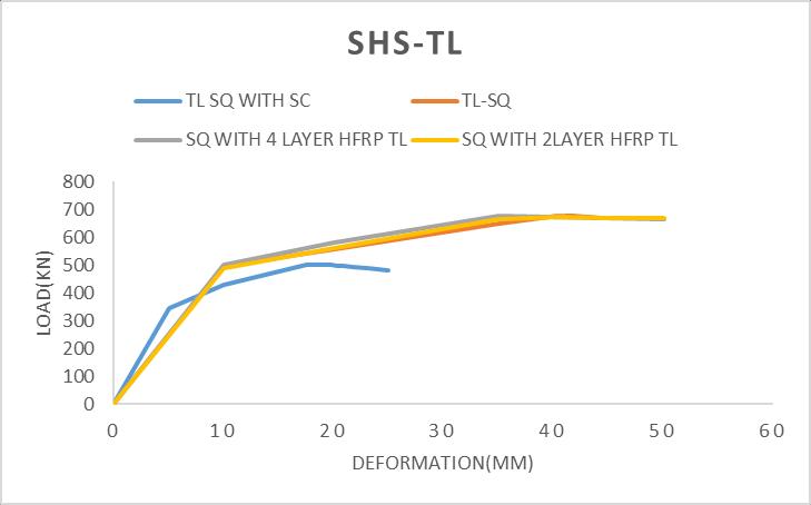
Table 14: ComparisontableofSHSwrappedin2and4 layersofhybridFRPundertensileloading
Load type Models Deformation (mm) Load(KN)
Tension TLSQ 41.077 675.71
Tension TLSQWITH SC 19.188 500.23
Tension 4LAYERFRP TLSQWITH SC
Tension 2LAYERFRP TLSQWITH SC
6.2.3 Torsional loading
Fig 36: BoundaryconditionofSHSwrappedin2and4 layersofhybridFRPundertensileloading
35 674.84
50 674.16
Fig 37: TotaldeformationfiguresofSHSwrappedin2and 4layersofhybridFRPundertensileloading
Model namesdesignatedfortorsional loadingaregivenas follows:
Table 15: Modelnamesindetailfortorsionalloading
Model name Names in detail
TRSQ TorsionalloadinginSquareHollow Section
TRSQWITHSC TorsionalloadinginSquareHollow SectionwithSurfaceCorrosion
4LAYERFRPTRSQ WITHSC HybridFRPwrappedin4layersin Squarehollowsectionintorsional loading
2LAYERFRPTRSQ WITHSC HybridFRPwrappedin2layersin Squarehollowsectionintorsional loading
Fig 39: BoundaryconditionofSHSwrappedin2and4 layersofhybridFRPundertorsionalloading
Fig-38: LoadingdiagramsofSHSwrappedin2and4layers ofhybridFRPundertensileloading
© 2022, IRJET | Impact Factor value: 7.529 | ISO 9001:2008 Certified Journal | Page3374
International Research Journal of Engineering and Technology (IRJET) e ISSN: 2395 0056
Volume: 09 Issue: 06 | Jun 2022 www.irjet.net p ISSN: 2395 0072
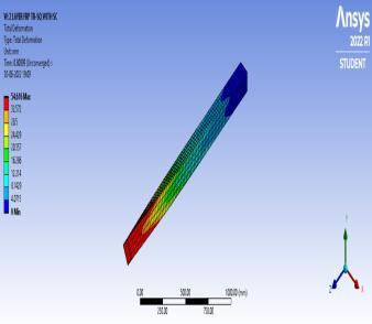
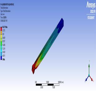
Fig 40: TotaldeformationfiguresofSHSwrappedin2and 4layersofhybridFRPundertorsionalloading
Fig-43: LoaddeformationrelationshipofSHSundertensile loading
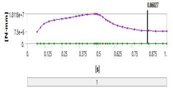
Fig-41: LoadingdiagramsofSHSwrappedin2and4layers ofhybridFRPundertorsionalloading
Table 16: ComparisontableofSHSwrappedin2and4 layersofhybridFRPundertensileloading
Load type Models Deformation (mm) Load(KNm)
Torsion TRSQ 94.528 18.368 Torsion TRSQWITH SC 35.976 13.007
Torsion 4LAYERFRP TRSQWITH SC
Torsion 2LAYERFRP TRSQWITH SC
52.983 18.12
54.616 17.99
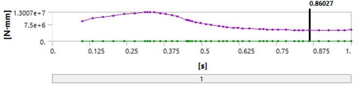
Fig 44: LoaddeformationrelationshipofSHSunder torsionalloading
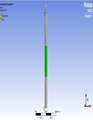
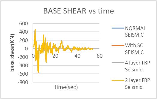
A multi storeyed frame having dimensions 3.6m x 3.6m is taken for the analysis under seismic loading. Surface corrosionisgiveninthebottommostcorneroftheframeas thebaseshearfirsttransferstothecorner.Itisthenwrapped by using 2 and 4 layers of hybrid FRP composites. In this study EL Centro earthquake is taken which has a time durationof55seconds.
Modelnamesforseismicanalysisgivenareasfollows:
Table 17: Modelnamesindetailforseismicloading
Model name Names in detail
Fig-42: LoaddeformationrelationshipofSHSunder compressionloading
NORMALSEISMIC Seismicloadinginmulti storeyed framewithoutcorrosion
© 2022, IRJET | Impact Factor value: 7.529 | ISO 9001:2008 Certified Journal | Page3375
International Research Journal of Engineering and Technology (IRJET) e ISSN: 2395 0056
Seismicloadinginmulti storeyed framewithSurfaceCorrosion
WITHSCSEISMIC
4LAYERFRP SEISMIC HybridFRPwrappedin4layers inmulti storeyedframein seismicloading
2LAYERFRP SEISMIC HybridFRPwrappedin2layers inmulti storeyedframein seismicloading

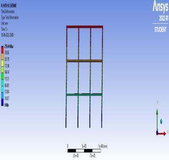
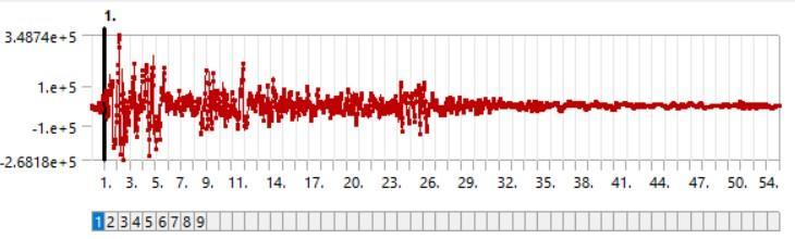
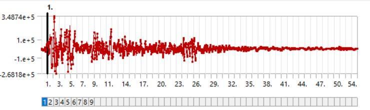
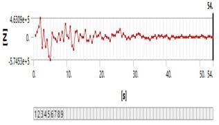
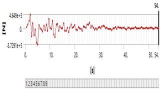
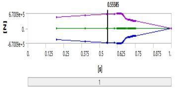
Fig 48: Forcereactiondiagramsofmulti storeyedframe withoutcorrosionandwithsurfacecorrosioninthebottom mostcornerunderseismicloading
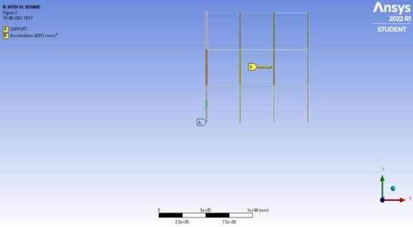
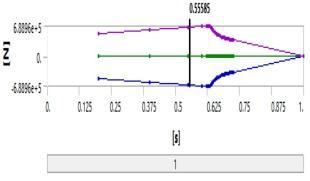
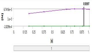
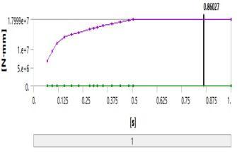
Fig 49: Time historyanalysisofamulti storeyedframe withoutcorrosionunderseismicloading
Fig 45: Multi storeyedframewithoutcorrosion
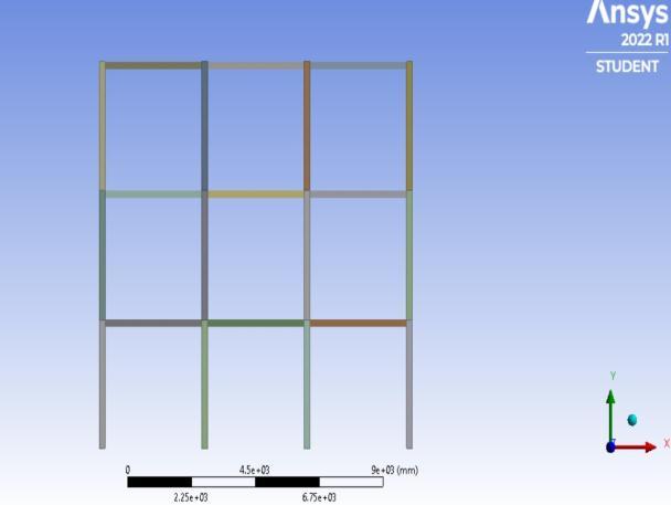
Fig 46: Multi storeyedframewithsurfacecorrosioninthe bottommostcorner
Fig 50: Time historyanalysisofamulti storeyedframe withsurfacecorrosionunderseismicloading
Note:Timehistoryanalysisisastep by stepanalysisofthe dynamicresponseofastructuretoaspecifiedloadingthat may vary with time. Time history analysis is used to determinetheseismicresponseofastructureunderdynamic loadingofrepresentativeearthquake
Fig 47: Totaldeformationfiguresofmulti storeyedframe withoutcorrosionandwithsurfacecorrosioninthebottom mostcorner
Volume: 09 Issue: 06 | Jun 2022 www.irjet.net p ISSN: 2395 0072 © 2022, IRJET | Impact Factor value: 7.529 | ISO 9001:2008 Certified Journal | Page3376
International Research Journal of Engineering and Technology (IRJET) e ISSN: 2395 0056
Volume: 09 Issue: 06 | Jun 2022 www.irjet.net p ISSN: 2395 0072
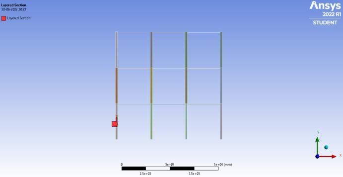
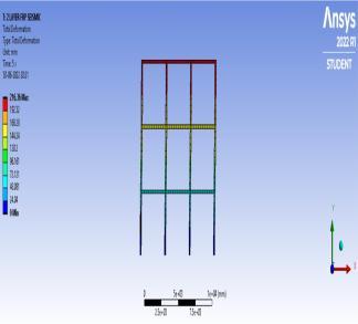
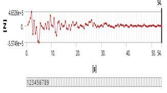
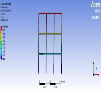
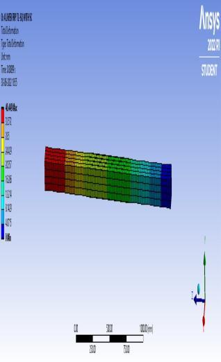
Fig 51: FigureofhybridFRPwrappedin2and4layersin thebottommostcornerhavingsurfacecorrosion
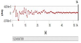
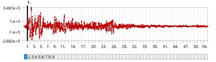
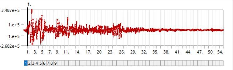
Fig 55: Timehistoryanalysisofmulti storeyedframe strengthenedusing4layersofhybridFRPcomposites
Table 18: Comparisontableofseismicloading
MODELS Storeydeflection (mm) Base shear(KN))
NormalSeismic 248.74 464.9
WithSCSeismic 259.44 463.09
4layerFRPSeismic 216.01 463.26 2layerFRPSeismic 216.36 463.14
Fig-52: Totaldeformationfiguresofmulti storeyedframe strengthenedusing2and4layersofhybridFRP composites
Fig 53: Forcereactiondiagramsofmulti storeyedframe strengthenedusing2and4layersofhybridFRP composites
Fig 56: Storeydeflection deformationrelationshipunder seismicloading
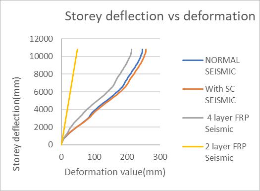
Fig 54: Timehistoryanalysisofmulti storeyedframe strengthenedusing2layersofhybridFRPcomposites
© 2022, IRJET | Impact Factor value: 7.529 | ISO 9001:2008 Certified Journal | Page3377
International Research Journal of Engineering and Technology (IRJET) e ISSN: 2395 0056
Volume: 09 Issue: 06 | Jun 2022 www.irjet.net p ISSN: 2395 0072
7. UnderSeismicloading,itisobtainedthatthemulti storeyed frame with corrosion has 10.7 KN more storeydeflectionthanmulti storeyedframewithout corrosion.
8. UnderSeismicloading,itisobtainedthatthemulti storeyedframewithoutcorrosionhas1.81KNmore base shear than multi storeyed frame with corrosion.
9. Underallloadingtypes,itisobtainedthat2layersof Hybrid FRP and 4 layers of Hybrid FRP used for strengthening SHS and multi storeyed frame has almostsimilarvalues.
Fig 57: BaseShear timerelationshipunderseismicloading
From the comparison charts and graphs of Square HollowSectionsandCircularHollowSections,
1. Undercompressionloading,itisobtainedthatthe circularhollowsectionwithoutcorrosionandwith corrosion has more load carrying capacity than squarehollowsectionbyaloadamountof36.98KN and66.29KNrespectively.
2. Undercompressionloading,itisobtainedthatthe circularhollowsectionwithoutcorrosionandwith corrosionhasamoreamountofdeformationthan thesquarehollowsectionbyadeformationamount of11.388mmand10.646mmrespectively.
3. UnderTensileloading,itisobtainedthatthesquare hollowsectionwithoutcorrosionandwithcorrosion has more load carrying capacity than Circular Hollowsectionbyanamountof33.01KNand24.52 KNrespectively.
4. UnderTensileloading,itisobtainedthatthesquare hollowsectionwithoutcorrosionandwithcorrosion has some amount of more deformation which is actuallyneglectiblethanCircularHollowsectionby anamountof0.823mmand1.188mmrespectively.
5. Under Torsional loading, it is obtained that the squarehollowsectionwithoutcorrosionandwith corrosion has more load carrying capacity than CircularHollowsectionbyanamountof26.93KN and9.662KN respectively.
6. Under Torsional loading, it is obtained that the squarehollowsectionwithoutcorrosionandwith corrosion has some amount of more deformation which is actually neglectible than Circular Hollow sectionbyanamount of0.003mmand2.388mm respectively.
10. Itisclearthat2layersofHybridFRP isenoughto mitigatethestrengthlostduetosurfacecorrosion.
FromtheanalysisofSHSandCHSsteelmembersusing ANSYSSoftwareitisconcludedthat:
1. FromthecomparisonchartsandgraphsofSHSand CHS, Square Hollow Section steel members have more load carrying capacity than that of Circular HollowSectionedmembers
2. Intheanalysisofmultistoreyedframeunderseismic loading,baseshearobtainedafterstrengtheninghas overcomethevaluefromthatofcorrodedmodel.
3. 2 layers of Hybrid FRP Composites is enough to mitigatethestrengthlostduetosurfacecorrosionin SquareHollowSection.
[1].A.H Keykha, “Strengthening of deficient steel sections usingCFRPCompositeundercombinedloading”,Mechanics ofadvancedcompositestructures,Vol.7,2020,pp287 296
[2].AmirHamzehKeykha,”TheeffectofCFRPstrengthening onthebehaviorofdeficientsteelbeamsunderconcentrated and distributed loading”, Indian Journal of Engineering & MaterialsSciences,Vol.27,April2020,pp438 444.
[3].AmirHamzehKeykha, ”Carbon fibrestrengtheningof deficient hollow steel sections under combined loading”, Proceedings of the Institution of Civil Engineers, Vol. 172, July2019,pp609 620
[4]. Amir Hamzeh Keykha, ” Behavior of Deficient Steel Members Strengthened Using CFRP Under Combined CompressiveLoadandTorsional Moment”,AUTJournalof CivilEngineering,Vol.2,June2018,pp59 68.
[5].NadimIShbeeb,RajaiAl Rousan,MohsenA.Issa,Haritha Al Salman,”Impactofbondedcarbonfibrecompositeonthe
International Research Journal of Engineering and Technology (IRJET) e ISSN: 2395 0056
Volume: 09 Issue: 06 | Jun 2022 www.irjet.net p ISSN: 2395 0072
shearstrengthofreinforcedconcretebeams”,Proceedingsof theInstitutionofCivilEngineers,Vol.171,May2018,pp364 379.
[6].S.BKandekar,R.STalikoti,”Studyoftorsionalbehaviorof reinforcedconcretebeamsstrengthenedwitharamidfiber strips”, International journal of advanced structural engineering, Vol.10,2018,pp465 474
[7].A.HKeykha,”Numericalinvestigationonthebehaviorof SHS steel frames strengthened using CFRP”, Steel and CompositeStructures,Vol.24, 2017,pp561 568.
© 2022, IRJET | Impact Factor value: 7.529 | ISO 9001:2008 Certified Journal | Page3379