International Research Journal of Engineering and Technology (IRJET) e ISSN: 2395 0056

International Research Journal of Engineering and Technology (IRJET) e ISSN: 2395 0056
1,2,3, B Tech Student, Department of Mechanical Engineering Mangalam College of Engineering,Kerala,India 686631
4Assistant Professor, Dept. of Mechanical Engineering, Mangalam College of Engineerimg,Kerala,India 686631 ***
Abstract In automotive engineering, the wheels are one of the most critical components especially rims and their function is of vital importance for human safety. Predicting the fatigue life of the wheel accurately is one of the major challenges lying ahead for the wheel manufacturers. Fatigue life is a key consideration in designing an automotive wheel. In this study, an automotive wheel rim has been modeled in order to analyze stress and fatigue analysis using the finite element method. Simulation of fatigue loading is done by S N curve and the expected life of rim is predicted. The expected life of any automotive component is to be well studied beforehand so that the risk of accidents during real service conditions can be reduced to a larger extent. Finite Element Method (FEM) has evolved as a resourceful tool for analyzing various components under a variety of operating conditions." It is being used not only to predict the critical points bearing the highest stress in a wheel but also to predict its fatigue life". The 3 dimensional model of the wheel was designed using CATIA. Then the 3 D model was imported into ANSYS. Static structural analysis is carried out to estimate the fatigue life, total deformation, and equivalent stress developed in the wheel rim. The results were optimized among three different materials Structural Steel, Aluminum alloy, and Magnesium Alloy.
Key Words: (Finite Element analysis, ANSYS, Stress life, Static analysis, Car rims, Fatigue, Stress concentration, CATIA)…
The tire is an important part of the car as it supports the weight of the car and helps the tire to stay in touch with theroad.Thetireisunderverydangerousconditions.The wheel is designed to meet certain safety and engineering standardstoprovidehighperformanceandefficiency.The wheelshouldbeabletohandletheshockandvibration,as wellastheweightofthecaranditsoccupants;itshouldbe lightweightbutextremelystrong.
In this case, the tire is put into a series of testing during productiontoensurethatonlythehighestqualitytiresare properly removed from the market. In the design and design of the wheels, three main tests are used. Circular bendingtests,radialfatiguetests,andimpactassessments
are three. They are used to set the model wheel by its movementintermsoffatigueanddurability.
Fatigue fractures, as a result, are caused by the formation of small cracks that extend by adding long term stress. However, the nature of stress is different. Fatigue fracturesarecausedbycyclicalloadsonobjects,resulting from the process of crack nucleation and existing cracks [1]
The tension caused by circulatory stress is usually sinusoidal with the letter and varies with the frequency with which it is used [2]. Each height is marked by the mass of the main stress or the minimum of the minimum pressure, both with equal or opposite sign (thickness and pressure respectively). The pressure applied can be torsional,tensile,orflexural.
Equilibrium for the biaxial notch type loading equity was proposed by some researchers [3], and was used to measure the fatigue life of a passenger car tire during a fatigue test under air pressure conditions. They realized that when the analytical results from the computer program were compared with the actual fatigue test results,theresultswerepositive.
LuandWei[4]usedtheCosmossoftwaretomodelafixed feature of the HS6061T6 bus rack, which was used to replicate circulating fatigue tests. The life cycle of the rim hasbeenimprovedtomorethan1.0x105,indicatingthat theproposedmethodofanalyzingthelimitingfactorwasa good and effective way to predict the fatigue life of aluminumrims.
Some researchers [5] have used ABAQUS software to mimic circular fatigue testing by constructing a specific feature model for the fixed load of aluminum wheels. The benchmark test results of a rotating aluminum tire tire revealed that failure and implementation of fractures occurred near the hub hole area, which was consistent withthefindings.
The current study shows a direct method for modeling a motor rim in CATIA, as well as a systematic simulation of rimpressure,bending,andradialfatiguetesting.
Volume: 09 Issue: 06 | June 2022 www.irjet.net p ISSN: 2395 0072 © 2022, IRJET | Impact Factor value: 7.529 | ISO 9001:2008 Certified Journal | Page3330
International Research Journal of Engineering and Technology (IRJET) e ISSN: 2395 0056
Volume: 09 Issue: 06 | June 2022 www.irjet.net p ISSN: 2395 0072
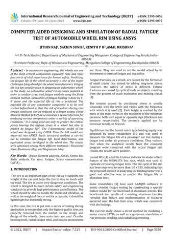
Table 1 summarizes wheel rim specifications. The CAD model of the rim is called the mathematical model here. The CATIA built wheel uses a number of features such as rotating features, sweeping features, boss extrude base and extrude cut, fillet and overhead features for better analysis.Adrawingisusedtomakeawheelmodel.Thisis done to ensure that when modeling the paint, the real stateoftherimisapplied,minimizingimperfections.
CATIAissoftwareusedtocreateandeditobjects.InCATIA and the design and modeling feature is available. Design refers to the process of creating something new or repairing an existing one. To write an outline means a representation or idea of something. Modeling means creating and converting 2D into 3D. Using the CATIA software,createawheelrimmodel
4. Using a circular pattern a specific design is found throughouttheline.
5. By re selecting the face draw a circle and rotate it usingacircularpattern.
6.FromtheholesusethePOCKEToption.
7.AndfinallyusingtheEDGEFILLEToptiontheedges havebeenfittedtocompletethefinal.
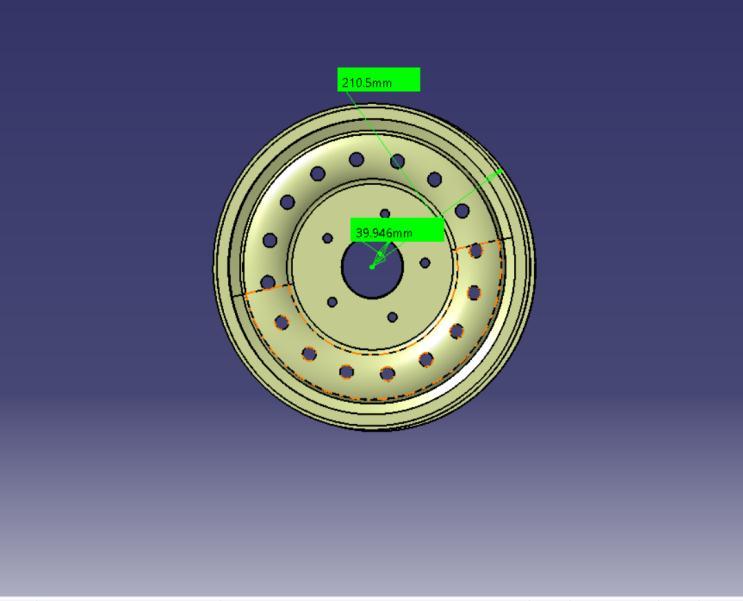
Fig 2: 3DWheelRim
Fig 1:WheelRimWithDimension
Rimdiameter 421mm Rimwidth 174.909mm Offset 145.595mm PCD 70mm Hubdiameter 39.946mm
Table 1:WheelRimDimension
1.Drawaprofilepictureofthewheelrim.
2.Nowrotatetheprofilebodyrelativetotheyaxis.
3. By selecting the wheel surface, the required design drawn on the surface is removed using the POCKET function.
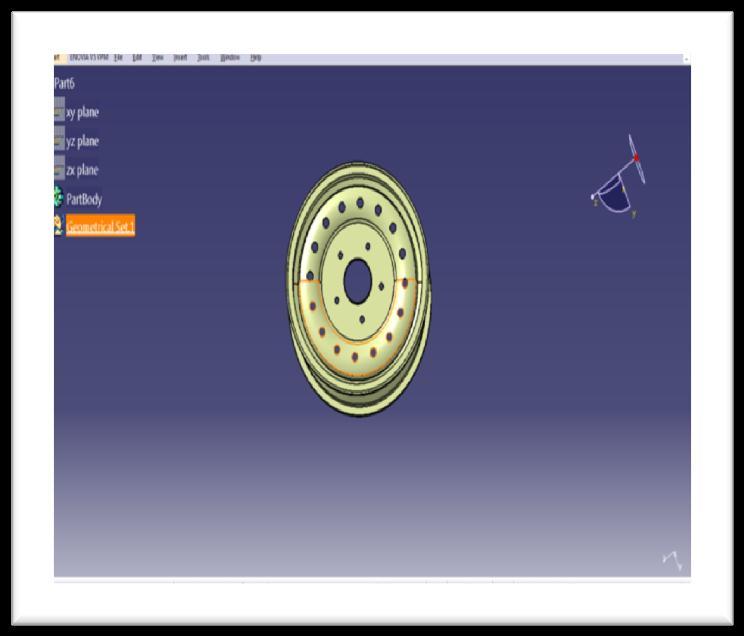
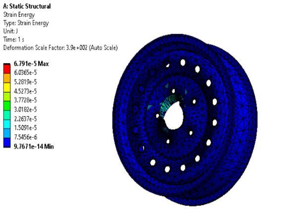
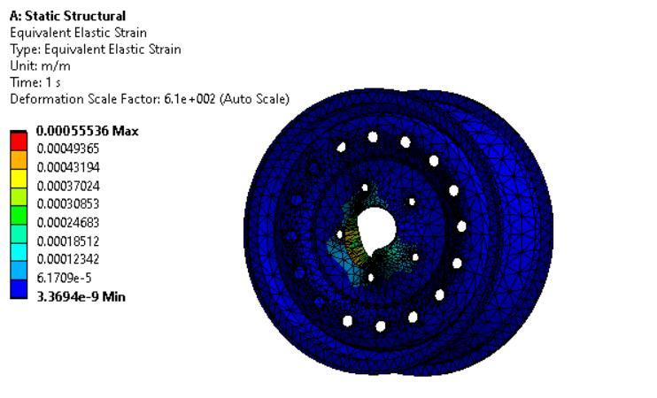
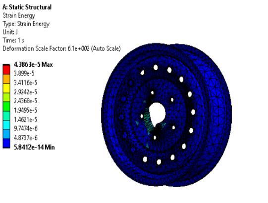
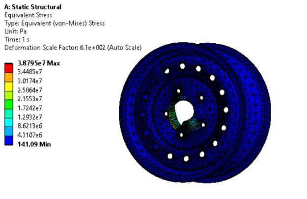
Stable stress analysis is used to determine the dynamic pressure. The radial load (Fr) load and the estimated wheel pressurecausethepressurein the wheel (Pi)to be distributed. Fatigue stress found in static stress analysis was found to be reliable [6]. ANSYS was used for this project.Workbenchisusedforthisstatisticalanalysis.

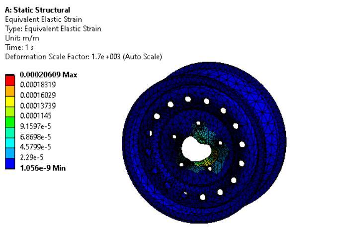
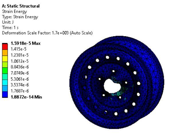
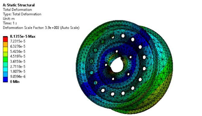
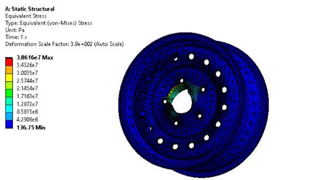
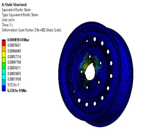
Staticstructuralandfatigueanalysiswasdoneon threedifferentmaterialsnamelyMagnesiumalloy, Structural Steel and Aluminium alloy and the resultswererecorded.
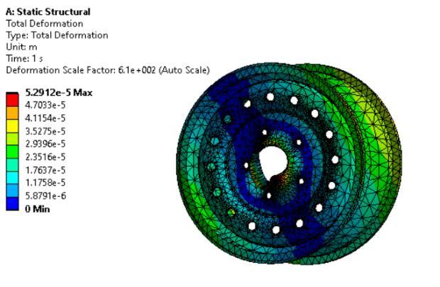
The total deformation of Magnesium alloy is 0.054816m which is higher as compared to StructuralSteelandAluminium.
International Research Journal of Engineering and Technology (IRJET) e ISSN: 2395 0056
Volume: 09 Issue: 06 | June 2022 www.irjet.net p ISSN: 2395 0072
The maximum stress of Steel is recorded to be 4406.930 Mpa which is higher as compared to MagnesiumandAluminium.
HigherstrengthisforMagnesiumalloywhichisof 0.0457473Joules.
Based on deformation Magnesium alloy is better but considering the feasibility of the three materials Structural Steel is the most viable option.
Hence Structural Steel is commonly used in commercialvehicles.
[1] Emmanuel M. Adigio and Ebughni O. Nangi (2014) Computer Aided Design and Simulation of Radial Fatigue Test of Automobile Rim Using ANSYS, Journal of Mechanical and Civil Engineering (IOSR JMCE) e ISSN: 2278 1684,p ISSN: 2320 334X, Volume 11, PP 68 73
[2] Jaspreet Singh, Siddhartha Saha (2015) "Static analysis of alloy wheel using ANSYS",International Journal of Research in Engineering and Technology (IJRET),Volume4Issue7,ISSN2319 1163
[3] K. Srinivasa Rao, M .Rajesh, G.Sreedhara Babu(2017) "Design And Analysis of Alloy Wheel", International Research Journal of Engineering and Technology (IRJET),Volume4Issue6,ISSN2395 0072
[4] Gamachisa Mitiku Tadesse(2017) "Modeling and AnalysisofCarWheel",InternationalResearchJournal of Engineering and Technology (IRJET),Volume 4 Issue2ISSN2395 0072.
[5] Dr. M. S. Hebbal, Mukunda Dabair(2019) "Static Structural, Modal and Harmonic Analysis of Alloy Car Wheel Rim using ANSYS Workbench", International Journal of Engineering Research & Technology (IJERT),Vol8Issue7,ISSN2278 0181
[6] R. Ashok Kumar(2019) "Experimental Studies of Optimization of Automotive wheel Rim using ANSYS", International Journal of Trend in Scientific Research and Development (IJTSRD),Volume 3 Issue 3,ISSN 2456 647
2022, IRJET | Impact Factor value: 7.529 | ISO 9001:2008 Certified Journal |